Konig & Meyer 11905 User manual

AUFSTELL-/BEDIENUNGSANLEITUNG
11905 Schallschutzelement
für Orchesterstühle mit Rückenlehne
- Der gewölbte Plexiglasschirm dämpft den Schall und mindert die Belastung,
-welche aus dem Rückraum kommend auf den Orchestermusiker einwirkt.
- Dieser Schirm ist in der Höhe, im Abstand und im Neigungs winkel stufenlos
-einstellbar und kann dadurch höchst individuell angepasst werden.
- Einfache Handhabung in Aufbau und Betrieb, insbesondere
-durch die schnelle und wirkungsvolle Aufnahme-Steck-
-verbindung des Schirmes.
- Erweiterbar mit K&M Akustik Absorber 11901.
SICHERHEITSHINWEISE
Vielen Dank, dass Sie sich für dieses Produkt entschieden haben. Diese Anleitung
informiert Sie über alle wichtigen Schritte bei Aufbau und Handhabung. Wir
empfehlen, sie auch für den späteren Gebrauch aufzubewahren.
1. EINSATZBEREICH
- 13420-000-55 Musikerstuhl
- 13430-000-55 Orchesterstuhl
- 13440-000-55 Orchesterstuhl
- 13460-019-55 Bass-Stuhl
- 13470-019-55 Schlagzeug-, Cello-, Harfenstuhl
- 13480-019-55 Pauken-, Dirigentenstuhl
2. BESTANDTEILE
Bitte Sichtprüfung vornehmen, ob alle Teile vorhanden
und in Ordnung sind (insbes. Schraubverbindungen).
ASchallschutzplatte mit Aufnahme-Steckverbindung
BAuszugrohr mit Schwenkgelenk
CHalterung mit Klemmplatte plus lose Klemmplatte
3. MONTAGE an den STÜHLEN
3.a 13420 und 13430:
3.a Hinweis: beide Klemmplatten müssen mit einem
3.a Führungsplättchen ausgestattet sein (Lieferzustand)
3.1 Anlegen der Klemmplatten um das Rohr der Rückenlehne:
3.1 a. Halterung mit Klemmplatte
3.1 b. Lose Klemmplatte
3.2 Die Schrauben der losen Klemmplatte bbis zum
3.2 Anschlag in die Schlitze der Halterohrplatte aschieben.
3.3 Flügelmuttern beidseitig und gleichmäßig fest anziehen.
3.4 Der Klemmspalt yzwischen den Platten muss auf beiden
3.4 Seiten gleich groß sein.
3.b 13440, 13460, 13470 und 13480:
3.0 Beide Führungsplättchen werden von den Klemmplatten
3.0 abgezogen.
3.0 Wir empfehlen sie gut aufzubewahren.
Die Montage am Stuhl erfolgt wie in den Punkten 3.1 bis 3.4
beschrieben.
4. MONTAGE der PLATTE am
4. GELENK des AUSZUGROHRES
4.1 Sicherstellen, dass das Gewinde der
4.1 Rändelschraube nicht herausragt.
4.2 Schallschutzplatte Aam Gelenk befestigen.
4.2 Dazu die Steckplatte bis zum Anschlag in
4.2 die Aufnahme-Steckverbindung schieben.
4.3 Rändelschraube nun fest anziehen, wodurch
4.3 die Schallschutzplatte sicher fixiert ist.
4.3 Erst durch Lösen dieser Schraube kann die Platte
4.3 wieder abgenommen werden.
Die DEMONTAGE erfolgt in umgekehrter Reihenfolge.
- Vor und nach Benutzung des Schallschutzes bitte Sichtprüfung
-vornehmenund auf Vollständigkeit, Gängigkeit und mögliche
-Schäden überprüfen.
- Ein beschädigtes Produkt darf zunächst nicht weiter eingesetzt
-werden bzw. erst nach qualifizierter Wiederinstandsetzung.
- Aufgrund seiner Transparenz kann der Plexiglasschirm leicht
-übersehen und in Konsequenz daran angestoßen werden. Wir
-empfehlen Kennzeichnungen oder Einsatz des Absorbers 11901
- Pflegliche und sorgsame Behandlung erhält die Funktions-
-tüchtigkeit, Langlebigkeit und dient nicht zuletzt der Sicherheit
- Auf die Festigkeit der Schraubverbindungen achten.
- Die Möglichkeit das Produkt zu verstellen, birgt natur gemäß
-Einklemmgefahren und erfordert stets umsichtige Handhabung.
- Vor widrigen äußeren Einflüssen schützen (Nässe, Wind, Stöße).
- Beachten Sie auch die Sicherheitshinweise des Orchester-
-stuhles an welchem der Schallschutz befestigt ist.
1. EINSATZBEREICH 2. BESTANDTEILE
4. MONTAGE der PLATTE
3.b MONTAGE an den STÜHLEN
3.b 13440, 13460, 13470 und
3.b 13480
3.a
MONTAGE AN
DEN STÜHLEN
13420 und 13430
3.0
Entfernung der Führungs-
plättchen an den Klemm-
platten
Lieferzustand:
mit vormontierten
Führungsplättchen
3.a
13420
13430
3.b
13440
13460
13470
13480

KÖNIG & MEYER GmbH & Co. KG
Kiesweg 2, 97877 Wertheim, www.k-m.de
11905-000-55 Rev.08 03-79-191-00 6/19
TECHNISCHE DATEN
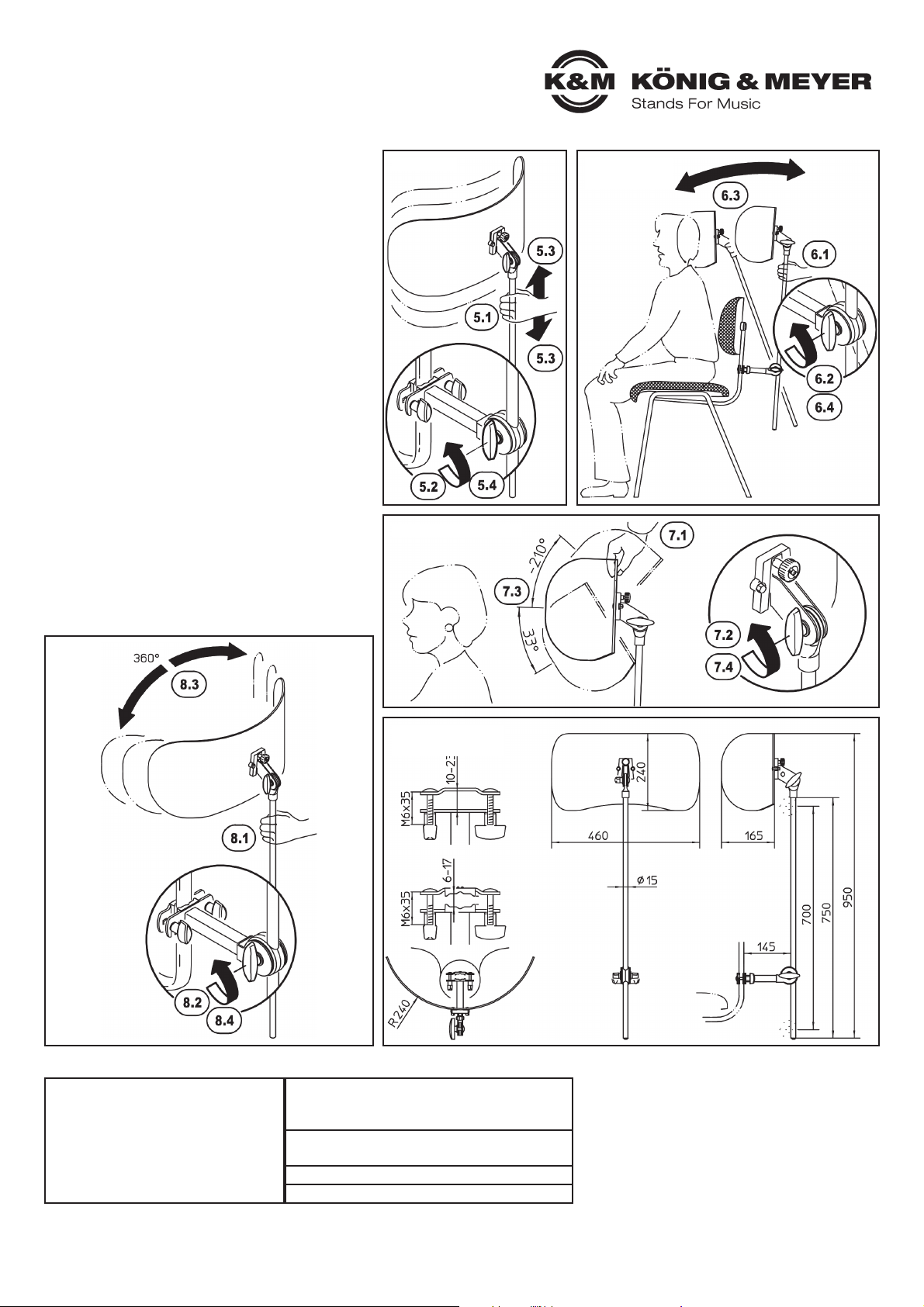
5. / 6. / 7. / 8. / 9. EINSTELLUNGEN und
ABMESSUNGEN
PRÜFEN, INSTANDHALTEN
Im Zusammenspiel mit den jeweiligen Stühlen kann die
Schallschutzplatte 11905 höchst flexibel eingestellt werden in:
- HÖHE,
- ABSTAND,
- NEIGUNGSWINKEL und
- RICHTUNG
5. HÖHE
5.1 Auszugstange festhalten,
5.2 Flügelmutter am unteren Gelenk etwas lösen,
5.3 Auszugstange wie gewünscht ein- oder ausfahren,
5.4 Flügelmuttern wieder festziehen.
6. ABSTAND zum KOPF
6.1 Auszugstange festhalten,
6.2 Flügelmutter am unteren Gelenk etwas lösen,
6.3 Auszugstange wie gewünscht neigen,
6.4 Flügelmutter wieder festziehen.
7. NEIGUNGSWINKEL
7.1 Schallschutzplatte halten
7.2 Flügelmutter am oberen Schwenkgelenk lösen,
7.3 Platte wie gewünscht neigen,
7.4 Flügelmutter wieder festziehen.
8. RICHTUNG
8.1 Auszugstange festhalten,
8.2 Flügelmutter am unteren Gelenk etwas lösen,
8.3 Auszugstange wie gewünscht drehen,
8.4 Flügelmutter wieder festziehen.
9. ABMESSUNGEN
- Spezielle Wartungsintervalle sind nicht erforderlich.
- Es empfiehlt sich regelmäßig die Gängigkeit und
-Festigkeit der Bauteile zu überprüfen, insbesondere
-die Schraubverbindungen.
- Zur Reinigung am besten ein leicht feuchtes Tuch und
-ein nicht scheuerndes Reinigungsmittel benutzen.
FEHLERSUCHE (F) und BESEITIGUNG (B)
F: Installation wackelt.
F: B: Überprüfen ob die Teile richtig angeordnet und die
F: B: Gewinde fest angezogen sind.
F: B: Ordnungsgemäßen Zustand des Stuhles sicherstellen.
ABMESSUNGEN
Platte: B x T x H: 460 x 165 x 240 mm
Auszugstange: ø15 x 700 (750) mm
GEWICHT
netto: 1,8 kg, brutto: 2,5 kg
KARTON 900 x 300 x 200 mm
ZUBEHÖR (optional) 11901 Akustik Absorber
MATERIAL
Rohre, Halterung, Schwenkgelenk:
- Stahl, pulverbeschichtet schwarz
Schrauben, Scheiben: - Stahl verzinkt
Pilz, Aufnahme-Steckverbindung:
- GD-Zink, pulverbeschichtet, schwarz
Kunststoff-Kleinteile: - PA, PE, schwarz
Schallschutzplatte: - PMMA, transparent
5. HÖHE
7. NEIGUNGSWINKEL
8. RICHTUNG
9. ABMESSUNGEN
- in mm -
6. ABSTAND
6. zum KOPF

SETUP / OPERATION INSTRUCTIONS
11905 Sound insulation
element for Orchestra seats with backrest
- The curved Plexiglas shield dampens noise and decreases the effect of the
-sound emanating from the back of the stage on the orchestra musician.
- This shield can be adjusted variable, to include distance and angle.
-It can be adjusted to meet each individual orchestra musician’s
-needs.
- Simple to install and operate, in particular through the
-fast and effective pin-connection- bolt.
- It can be expanded with K&M Acoustic absorber 11901.
SAFETY NOTES
Thank you for choosing this product. This instruction manual informs you about
the important steps to set up and handle the product. We recommend to keep
the manual in a separate place for a possible later use.
1. APPLICATION AREA
- 13420-000-55 Musician's chair
- 13430-000-55 Orchestra chair
- 13440-000-55 Orchestra chair
- 13460-019-55 Bass stool
- 13470-019-55 Chair for Percussion, Cello and Harp
- 13480-019-55 Chair for Kettledrums and Conductor’s
2. COMPONENTS
Please perform a visual inspection to ensure that all parts
and components are accounted for and in working order (in
particular screw connections).
ASound dampening plate with connection pin
BExtension tube with swivel joint
CBracket with clamping plate and loose clamping plate
3. MOUNTING on the CHAIRS
3.a 13420 and 13430:
3.a Note: Both clamping plates must be equipped with a
3.a guiding plate (delivery condition).
3.1 Positioning the clamping plates around the backrest tube:
3.1 a. Bracket with clamping plate
3.1 b. Loose clamping plate
3.2 Place the screws into the clamp plate bthrough the slits
3.2 of the main tube aas far as they will go.
3.3 Tighten the wing nuts on both sides using equal force.
3.4 The clamp space ybetween the plates must be the same
3.4 size on each side.
3.b 13440, 13460, 13470 and 13480:
3.0 Both guiding plates must be removed from the
3.0 clamping plates.
3.0 We recommend to store them safe.
The assembly on the chair is the same as described in points
3.1 to 3.4.
4. INSTALLATION of the PLATE on the
4. JOINT of the EXTENSION TUBE
4.1 Ensure that the threaded bolt of the knurled screw
4.1 does not stick out.
4.2 Mount the noise dampening shield to the joint.
4.2 Place the bracket Aas far as it will go into the
4.2 receptor bracket.
4.3 Tighten the knurled screw which secures the sound
4.3 dampening plate. The plate can only be removed if the
4.3 knurled screw is removed.
DISASSEMBLY is done in reverse order.
- Perform a visual inspection of the sound insulation for damage prior to
-and after use and ensure that it is in working order.
- A damaged product may not be used until it has been restored to
-working condition by a qualified technician.
- Due to its transparency, the Plexiglas shield can easily be overlooked,
-and people can inadvertently walk into them. We recommend that the
-seat back be marked or the use of acoustic absorber 11901
- Proper care maintains the working order, durability and also
-safety of the product.
- Be sure to ensure that the screw connections are tight.
- The fact that the product is adjustable, can result in the risk
-of pinching/wedging and requires careful use and handling.
- Protect again external influences (moisture, wind,
-being bumped into).
- Please also observe the safety notes of the musician's
-chairs, used with the sound insulation
1. APPLICATION AREA 2. COMPONENTS
4. INSTALLATION of the PLATE
3.b MOUNTING on the CHAIRS
3.b 13440, 13460, 13470 and
3.b 13480
3.a
MOUNTING
on the CHAIRS
13420 and 13430
3.0
Remove the guide plates
from the clamping plates
Delivered condition:
with pre-assembled
guiding plates
3.a
13420
13430
3.b
13440
13460
13470
13480
KÖNIG & MEYER GmbH & Co. KG
Kiesweg 2, 97877 Wertheim, www.k-m.de
11905-000-55 Rev.08 03-79-191-00 6/19
TECHNICAL DATA
5. / 6. / 7. / 8. / 9. ADJUSTMENTS and DIMENSIONS
CHECK, MAINTENANCE
The Sound insulation element 11905 can be used with a
variety of chairs. It can be adjusted in:
- HEIGHT,
- DISTANCE,
- ANGLE and
- DIRECTION
5. HEIGHT
5.1 Hold the extension tube,
5.2 loosen the wing nut of the lower joint a bit,
5.3 find the desired position of the extension tube by
extending or retracting it,
5.4 re-tighten the wing nut.
6. DISTANCE to the HEAD
6.1 Hold the extension tube,
6.2 loosen the wing nut of the lower joint a bit,
6.3 place the extension tube at the desired angle,
6.4 re-tighten the wing nut.
7. ANGLE
7.1 Hold the sound insulation plate
7.2 loosen the wing nut on the upper swivel joint,
7.3 place the plate at the desired angle,
7.4 re-tighten the wing nut.
8. DIRECTION
8.1 Hold the extension tube,
8.2 loosen the wing nut of the lower joint a bit,
8.3 place the extension tube at the desired angle,
8.4 re-tighten the wing nut.
9. DIMENSIONS
- Specific maintenance intervals are not required.
- We recommend that the operability and connections
-of the components are inspected from time to time.
- To care for the product, use a damp cloth and a
-non-abrasive cleaning agent
FAULT-FINDING (F) and REPAIR (R)
F: Installation is not stable.
F: R: Check to see if the parts are in the right positions
F: R: and the screws are properly tightened.
F: R: Ensure the chair is in proper working condition.
DIMENSIONS
Plate: W x D x H: 460 x 165 x 240 mm
Extension tube: ø15 x 700 (750) mm
WEIGHT
net: 1.8 kg, gross: 2.5 kg
BOX 900 x 300 x 200 mm
ACCESSORIES (optional) 11901 Acoustic absorber
MATERIAL
Tubes, brackets, swivel joint:
- Steel, powder coating, black
Screws, disks: - steel, galvanized
Swivel head, receptor bracket:
- GD Zinc, powder coating, black
Plastic-parts: - PA, PE, black
Sound insulation plate: - PMMA, transparent
5. HEIGHT
7. ANGLE
8. DIRECTION
9. DIMENSIONS
- in mm -
6. DISTANCE
6. to the HEAD
Table of contents
Languages:
Other Konig & Meyer Music Equipment manuals


