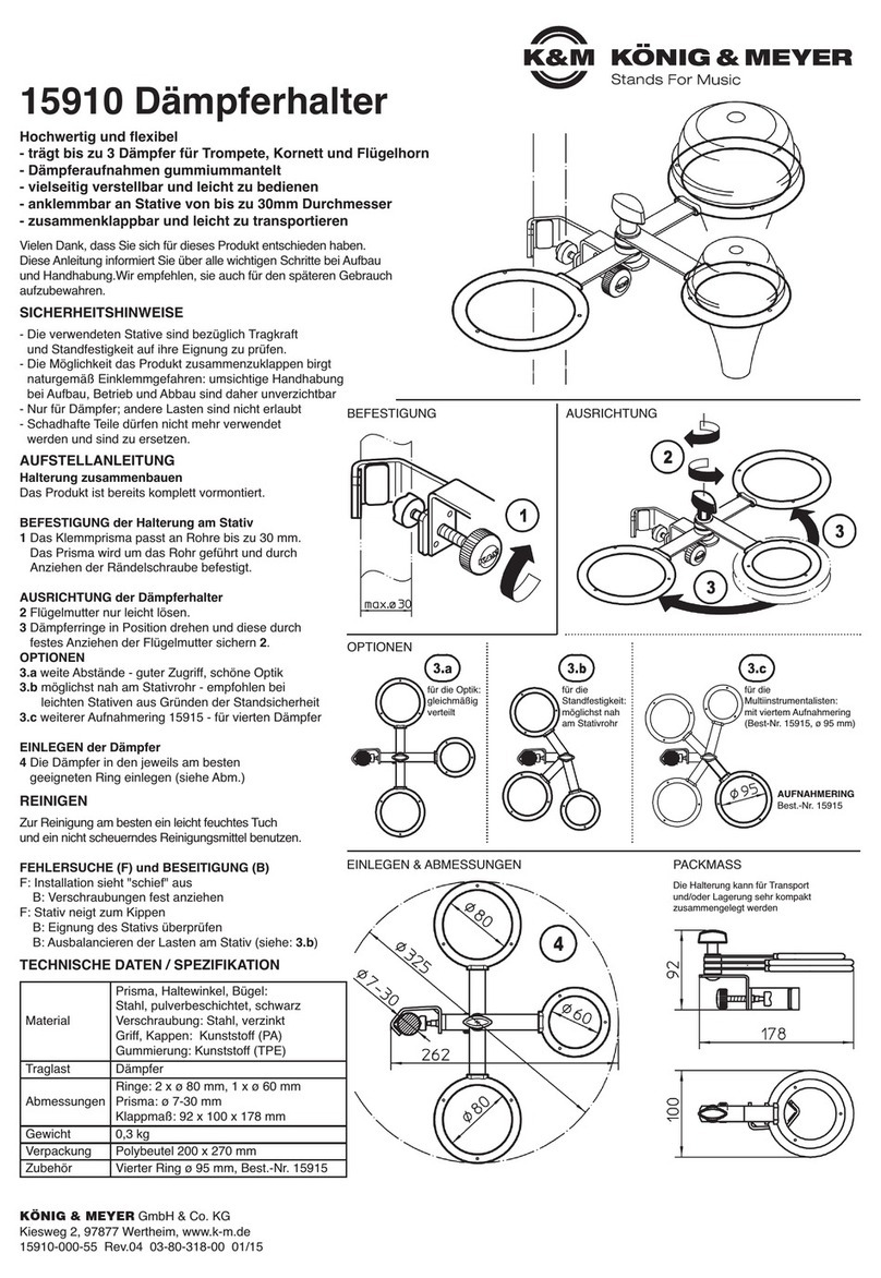
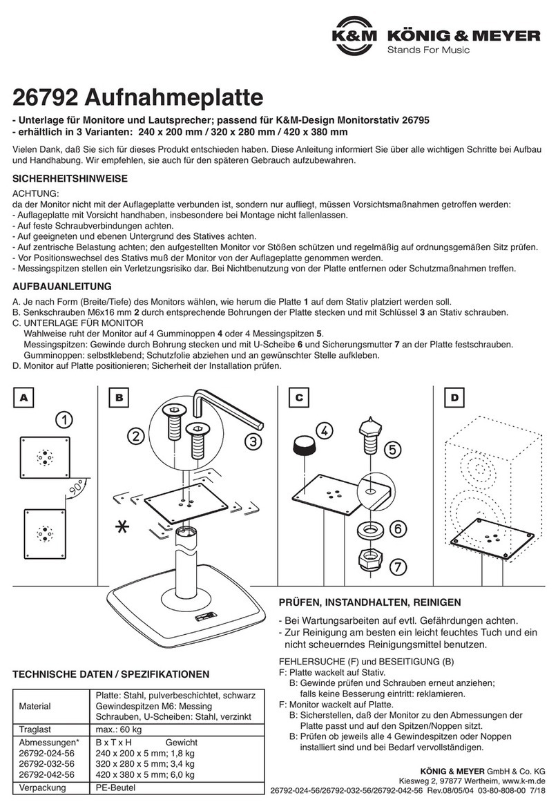
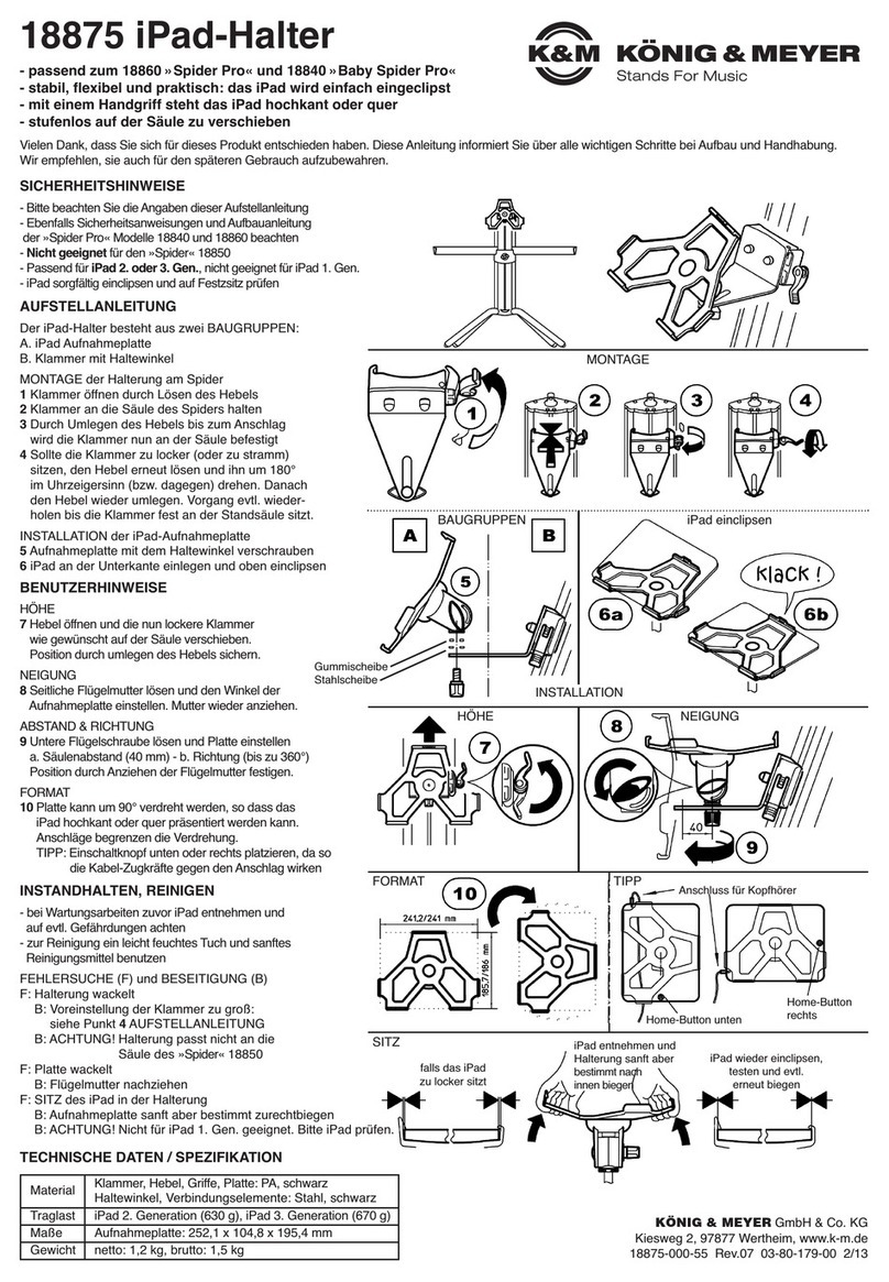
Konig & Meyer 12227 User manual

AUFSTELLANLEITUNG
Halterung zusammenbauen A Platte mit verstellbarem
A Haltewinkel
Die Halterung besteht aus drei Baugruppen, BKlammer mit Ausleger
welche miteinander verschraubt werden: CVerschraubungssatz
Vielen Dank, dass Sie sich für dieses Produkt entschieden haben. Bitte lesen und beachten Sie vor Aufbau und Betrieb dieses
Produkts sorgfältig diese Anleitung. Sie informiert Sie über alle wichtigen Schritte um eine sichere Handhabung zu gewährlisten.
Wir empfehlen, sie auch für den späteren Gebrauch aufzubewahren.
SICHERHEITSHINWEISE
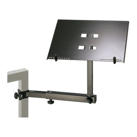
12227 Ablageplatte
BESTIMMUNGSGEMÄSSER GEBRAUCH
- Die Ablageplatte dient der Aufnahme von kleineren elektronischen Geräten
-wie Mixern, Controllern oder Tablets sowie für Percussion- und Musikzubehör
- Sie eignet sich zur Montage an Stativen mit Rohrdurchmesser von 25-42 mm
MERKMALE & FÄHIGKEITEN
- Geeignet für Tour, Home und Studio
- Eine Schaumstoffeinlage (3 mm) dämpft Vibrationen, verhindert Neben-
-geräusche und schont das abgelegte Equipment.
- In der Platte ist eine Aussparung für Verkabelung
- Mit integriertem Dosen-/Becherhalter (ø 70 x 47 mm)
- Abstand und Ausrichtung der Platte sind individuell verstellbar
- Maße: Platte 253 x 331 x 20 mm, Klammer für ø 25-42 mm, Gewicht 2 kg
- Tragkraft: max. 5 kg vorbehaltlich Stativeignung siehe: Sicherheitshinweise
A. TRAGKRAFT der ABLAGEPLATTE: C. TRAGLAST:
A. - Die max. erlaubte Last beruht auf: C. - Ablageplatte möglichst nahe an das Stativ rücken
A. -a. der Tragkraft der Ablageplatte als solcher: die solide Stahlkonstruktion trägt C. - Traglast möglichst mittig auf der Platte ausrichten
A. -a. zentrische Lasten bis zu 5 kg
A. -b. der Standfestigkeit des Stativs:
A. -b. siehe folgenden Punkt B sowie Kap.11) - ggf. Last reduzieren
B. STATIV und UNTERGRUND (siehe auch Kap.11): D. HANDHABUNG:
B. - Eignung des Statives prüfen (u.a.: passen die Rohrdurchmesser? Tragkraft gegeben?) D. - Verschraubungen fest anziehen, jedoch nicht über fest
B. - Die Sicherheitshinweise der Stative sind zu beachten D. - Die Möglichkeit Teile des Produktes zu bewegen birgt naturgemäß
B. - Standfestigkeit prüfen. Diese ist nur gegeben, wenn das Gewicht der belasteten D. -Einklemmgefahren; umsichtige Handhabung bei Aufbau, Betrieb und Abbau
B. -Ablageplatte weder die Stativrohre zur Seite biegt, noch das Stativ auch nur entfernt D. -sind daher unverzichtbar
B. -zum Kippen bringt. Ggf. Test durchführen. D. - Bei Änderung der Einstellungen (Kap.: 3.-6.) ggf. zuvor die auf der
B. - Nur auf ebenem u. tragfähigem Untergrund abstellen. D. -Ablageplatte abgelegten Teile entfernen
AUFSTELLUNGANLEITUNG
1. BESTANDTEILE
Bitte Sichtprüfung vornehmen, ob alle Teile vollständig vorhanden und soweit er-
kennbar in Ordnung sind. Die Notenablage ist bereits vormontiert und besteht aus:
aKlammer mit Tragarm
bVerbindungselementen (b.1-5)
cAblageplatte
dDosen-/Becherhalter
eSchaumstoffeinlage (329 x 251 x 3 mm)
fDoppelklebepunkte (ø 15 mm) 6x
3. / 4. / 5. / 6. EINSTELLUNGEN
Die Ablageplatte ist sehr variabel einzustellen. Beachte: zuvor stets die Lasten entfernen.
3. HÖHE
3.1 Klemmschraube der Klammer lösen,
3.2 Klammer entlang des Stativrohres
3.2 verschieben und an gewünschter Stelle...
3.3 ...Klemmschraube wieder festziehen.
4. RICHTUNG - TRAGARM DREHEN
4.1 Klemmschraube der Klammer lösen,
4.2 Tragarm schwenken,
4.3 Klemmschraube wieder festziehen
5. ABSTAND VOM STATIVROHR
5.1 Flügelmutter lösen,
5.2 Ablageplatte verschieben (0-80 mm),
5.3 Flügelmutter wieder festziehen.
2. MONTAGE AM STATIV
2.1 Die Klammer ist für Rohre von ø 25-42 mm
2.2 Klammer um das Stativrohr legen
2.3 Klemmschraube festziehen

TECHNISCHE DATEN
Material
Tragarm, Ablageplatte, Klammer: Stahl, gepulvert
Schrauben, Plättchen, Mutter: Stahl, galvanisiert
Kappen, Griffe, Distanzen, Becher: PA-6, PLA
Einlage: Schaumstoff, schwarz
Traglast kleine Geräte, Percussion, Zubehör bis max. 5 kg
geringere Last bei unsicherem Stand
Maße
Ablageplatte innen: 330 x 252 x 20 mm
Schaumstoffeinlage: 329 x 251 x 3 mm
Klammer: für Rohre ø 25-42 mm
Dosenhalter: ø 70 x 4 7mm
Gewicht 2 kg
Verpackung Innen: 465 x 325 x 87 mm, 0,4 kg
AUFSTELLUNGANLEITUNG
BENUTZERHINWEISE
6. RICHTUNG - ABLAGEPLATTE DREHEN
6.1 Flügelmutter lösen,
6.2 ggf. Ablage vom Stativrohr wegschieben
6.3 Ablage verdrehen,
6.4 Ablage wieder ans Stativ schieben
6.5 Flügelmutter wieder festziehen
7. SCHAUMSTOFFEINLAGE
7.1 Die Schaumstoffeinlage ist nicht eingeklebt und kann nach Belieben
7.1 wieder entnommen werden.
7.2 Beachten Sie beim Einlegen die Position des Ausschnitts
7.2 für den Dosen-/ Becherhalter.
7.3 Beigefügt sind St.6 Doppelkleberonden ø 15 mm, um bei Bedarf die Einlage
7.3 in die Platte zu kleben.
8. VERKABELUNG – AUSSPARUNG
8.1 Die Freimachung in der Platte dient...
8.2 ...als Kabeldurchführung
8.3 ...um die Schaumstoffeinlage von unten anheben zu können
9. DOSEN-/BECHERHALTER
9.1 Der Dosenhalter eignet sich neben Dosen und Bechern auch zur Aufbewahrung
9.1 von Kleinteilen
9.2 Er ist in die Ablageplatte eingeclipst und kann bei Bedarf entnommen und anschlie-
9.2 ßend wieder eingedrückt werden. Achten sie auf das >clack<-Geräusch.
10. ÜBERSICHT GEEIGNETER K&M-STATIVE
10.1 Stative müssen über PASSENDE ROHRE verfügen: ø 25-42 mm
10.1 Dazu zählen:
10.1 - Notenstative: 11870,11888, 11889, 11899, 11940, 11960, 11965, 12330, 12331
10.1 - Mikrofonstative: 20800, 20811, 21411, 21430
10.1 - Monitorstative: 26720, 26740, 26754
10.1 - Boxenstative: 19500, 213, 21302, 21420, 21435, 21436, 21449, 21450, 21455,
10.1 - Boxenstative: 21460, 21463, 21467, 26734, 26735, 26737, 26750
10.1 - Leuchtenstative: 24610, 24620, 24624, 24625, 24630, 24640, 24645
WARTUNG
- Schonender Umgang erhält die Funktion, die Tragkraft und Langlebigkeit der Ablage
- Periodische Betätigung beweglicher Teile erhält deren Gängigkeit
- Wartungsarbeiten dürfen nur im unbelasteten Zustand durchgeführt werden.
- Beschädigt Teile dürfen nicht weiterverwendet werden; sie müssen ersetzt werden.
- Schmutz, Feuchtigkeit und ggf. Korrosion sind zu entfernen
- Zur Reinigung und Pflege ein leicht feuchtes Tuch und nicht scheuerndes
-Reinigungsmittel benutzen
11. STANDSICHERHEIT DER INSTALLATION
11.1 Die Installation (= Kombination aus Untergrund, Stativ, Ablageplatte und Traglast)
11.1 muss über AUSREICHENDE STANDSICHERHEIT verfügen. Einflussgrößen sind:
11.1 a. Untergrund: muss tragfähig und eben sein; schiefe Untergründe sind eine Gefahr
11.1 b. Stativ: je höher das Eigengewicht und je größer der Fußkreis, desto besser
11.1 c. Ablageplatte - c.1 Platte: so nahe wie möglich am zentralen Halterohr platzieren
11.1 c. Ablageplatte - c.2 Klammer: eher tief am Stativ befestigen
11.1 c. Ablageplatte - c.3 Tragarm: über einem der drei Beine ausrichten, nicht dazwischen
11.1 d. Traglast: max. 5 kg; muss bei Kippgefahr der Installation ggf. reduziert werden
11.2 Im Zweifelsfall empfehlen wir die Durchführung eines 5°-Kipptests.
11.2 TESTBEDINGUNGEN
11.2 Die gewählte Installation darf auf einer um 5° geneigten Ebene nicht umkippen.
11.2 WARNUNG!
11.2 Bei der Durchführung dieses Tests ist die Sicherheit zu gewährleisten
11.2 (Rechtzeitiges Abfangen des Stativs, Absperrungen, Sicherungsseile etc.).
11.2 Evtl. Fachpersonal hinzuziehen.
11.2 HINWEIS
11.2 Der 5°-Kipptest weist darauf hin, wie gut die Installation Seitenkräften widersteht.
11.2 Sein Bestehen bedeutet NICHT, dass der Betrieb der Installation auf einer bis zu
11.2 5° schiefen Ebene erlaubt ist. Vielmehr sind nur ebene Untergründe erlaubt.
11.3 MASSNAHMEN bei nicht bestandenem 5°-Kipptest sind beschrieben unter
11.3 11.1.a-d. Grundsätzlich sollte das Stativ nicht Gefahr laufen umzukippen - auch
11.3 bei ungünstiger Einstellung der Ablageplatte 12227
3. / 4. / 5. / 6. EINSTELLUNGEN
FEHLERSUCHE (F) und BESEITIGUNG (B)
F: Installation wackelt B: Prüfen ob die Teile richtig angeordnet und die Gewinde fest
F: Installation wackelt B: angezogen sind.
F: Installation wackelt B: Stative auf Standfestigkeit hin überprüfen
F: Dosenhalter sitzt locker. B: Teil bis zum Anschlag in die Bohrung der Platte pressen
F: Die Ablageplatte lässt B: Platte rausschieben 6.2, dann verdrehen und
F: sich nicht um 360° drehen B: wieder nach innen schieben 6.4 und sichern.
KÖNIG & MEYER GmbH & Co. KG
Kiesweg 2, 97877 Wertheim, www.k-m.de
12227-000-55 Rev.05 03-79-117-00 2/20
suboptimal:
- weit raus
- sehr hoch
- zwischen
-zwei Füßen
Beispiel:
Boxenstativ
214/6
ø 1320 mm
4,4 kg
Auflageplatte
nah am Stativ
etwas tiefer
befestigt
über einem
der Füße
theoretische
Kipplinien
Beispiel:
Orchesternotenpult
11960
ø 750 mm
3,7 kg
VORSICHT:
- weit raus
- sehr hoch
- zwischen
-zwei Füßen
- im Bereich
-der Kipplinie

AUFSTELLANLEITUNG
Halterung zusammenbauen A Platte mit verstellbarem
A Haltewinkel
Die Halterung besteht aus drei Baugruppen, BKlammer mit Ausleger
welche miteinander verschraubt werden: CVerschraubungssatz
Thank you for choosing this product. Please read and follow instructions carefully before installing and operating this product. They
inform you about all important steps so as to ensure safe handling. Please keep instructions for further reference.
SAFETY INSTRUCTIONS
12227 Tray
INTENDED USE
- The tray is designed to hold smaller electronic equipments such as mixers, controllers
-or tablets as well as accessories for percussion and music
- It is suitable for mounting on stands with a tube diameter of 25-42 mm
FEATURES & PROPERTIES
- Suited for touring, home and studio
- A foam insert (3 mm) dampens vibrations, prevents ambient noise
-and is gentle on the equipment.
- There is a recess for wiring in the surface
- It has an integrated can/cup holder (ø 70 x 47 mm)
- Distance and direction of the tray can be individually adjusted
- Dimensions: plate 253 x 331 x 20 mm, clamp for ø 25-42 mm, weight 2 kg
- Load capacity: max. 5 kg subject to stand suitability see: Safety instructions
A. LOAD CAPACITY OF THE TRAY: C. LOAD:
A. - The maximum permissible load depends on: C. - Place the support tray as close as possible to the stand
A. -a. the load capacity of the support tray as such: the solid steel structure C. - Preferably position the load in the centre of the tray
A. -a. carries centric loads up to 5 kg
A. -b. the stability of the stand:
A. -b. see the following point B as well as chapter 11.) – if necessary, reduce load
B. STAND AND BASE (see also chapter 11): D. HANDLING:
B. - Check suitability of the stand (e.g.: do the tube diameters fit? Load capacity given?) D. - Tighten the screws firmly, but do not overtighten
B. - Observe the safety instructions of the stands D. - The facility to move some components of the products may conceal trapping
B. - Check stability. This is only given if the weight of the loaded support tray D. -hazards; careful handling during assembly, operation and dismantling is
B. -does not bend the stand tubes to the side and on no account brings it to tilt. D. -therefore indispensable
B. -If necessary, carry out a test. D. - If the settings are changed (section: 3.-6.), remove before any parts placed
B. - Only place on level and stable flooring. D. -on the support tray
INSTALLATION INSTRUCTIONS
1. COMPONENTS
Please carry out a visual inspection to ensure that all components are present and as far
as perceptible in order. The sheet music tray is already pre-assembled and consists of:
aClamp with support arm
bConnecting elements (b.1-5)
cTray
dCan/cup holder
eFoam insert (329 x 251 x 3 mm)
fDouble sided adhesive dots (ø 15 mm) 6x
3. / 4. / 5. / 6. ADJUSTMENTS
The tray can be variably adjusted. Note: always remove the loads first.
3. HEIGHT
3.1 Loosen the clamp of the clamping screw,
3.2 move the clamp along the stand tube
3.2 and place it in the desired position...
3.3 ...tighten the clamping screw again.
4. DIRECTION - TURNING SUPPORTING ARM
4.1 Loosen clamping screw of the clamp,
4.2 rotate the support arm,
4.3 Retighten clamping screw
5. DISTANCE FROM STAND TUBE
5.1 Loosen wing nut,
5.2 position support tray (0-80 mm),
5.3 retighten wing nut.
2. MOUNTING ON THE STAND
2.1 The clamp is for tubes of ø 25-42 mm
2.2 Place the clamp around the stand tube
2.3 Tighten the clamping screw

TECHNICAL DATA
Material
Support arm, support tray, clamp: Steel, powder-coated
Screws, washers, nuts: Steel, galvanized
Caps, handles, spacer, cup: PA-6, PLA
Insert: Foam, black
Load capacity small devices, percussion accessories up to max. 5 kg
lower load when unsafe stand
Dimensions
Tray internal: 330 x 252 x 20 mm
Foam insert: 329 x 251 x 3 mm
Clamp: for tubes ø 25-42 mm
Can holder: ø 70 x 4 7mm
Weight 2 kg
Packaging Inside: 465 x 325 x 87 mm, 0.4 kg
ASSEMBLY INSTRUCTIONS
USER REFERENCES
6. DIRECTION - TURN TRAY
6.1 Loosen the wing nut,
6.2 push the tray away from the stand tube if necessary
6.3 Turn the tray,
6.4 push the tray back in direction stand
6.5 Tighten the wing nut again
7. FOAM INSERT
7.1 The foam insert is not glued and can be removed at will.
7.2 Please note the position of the cut-out for the can/cup holder,
7.2 when fitting the foam insert.
7.3 6 Double sided adhesive dots ø 15 mm are included to glue
7.3 the insert into the plate if required.
8. RECESS FOR WIRING
8.1 The clearance in the tray serves...
8.2 ...as cable bushing and
8.3 ...to lift the foam insert from below
9. CAN/CUP HOLDER
9.1 In addition to cans and cups, the holder can also be used for storing small parts.
9.2 the holder is clipped onto the tray. If required It can be removed and afterwards
9.2 pressed in again. Pay attention to the >clack<-noise.
10. OVERVIEW OF SUITABLE K&M-STANDS
10.1 Stands must have APPROPRIATE TUBES: ø 25-42 mm
10.1 These include:
10.1 - Music stands: 11870,11888, 11889, 11899, 11940, 11960, 11965, 12330, 12331
10.1 - Microphone stands: 20800, 20811, 21411, 21430
10.1 - Monitor stands: 26720, 26740, 26754
10.1 - Speaker stands: 19500, 213, 21302, 21420, 21435, 21436, 21449, 21450,
10.1 - Speaker stands: 21455, 21460, 21463, 21467, 26734, 26735, 26737, 26750
10.1 - Lighting stands: 24610, 24620, 24624, 24625, 24630, 24640, 24645
MAINTENANCE
- Careful handling preserves the function, the load capacity and longevity of the support
- Periodic operation of moving parts preserves their mobility
- Maintenance work may only be carried out in an unloaded condition.
- Damaged parts must not be used again and should be replaced or repaired
- Dirt, moisture and corrosion must be removed
- For cleaning and maintenance use a slightly damp cloth and a non-abrasive
-cleaning agent
11. STABILITY OF THE INSTALLATION
11.1 The installation (= combination of base, stand, tray and load) must have
11.1 SUFFICIENT STABILITY. Influencing factors are:
11.1 a. Surface: must be load-bearing and level; sloping floors are a danger
11.1 b. Stand: the higher the dead weight and the larger the base circle the better
11.1 c. Support tray - c.1 Tray: place as close as possible to the central support tube
11.1 c. Support tray - c.2 Clamp: fix rather deep-seated onto the stand
11.1 c. Support tray - c.3 Support arm: position above but not between
11.1 c. Support tray - c.3 one of the three legs
11.1 d. Load: max. 5 kg; may have to be reduced if the installation is in danger of tilting
11.2 In case of doubt, we recommend a 5° tilt test.
11.2 TEST CONDITIONS
11.2 The selected installation must not tip over on a plane inclined by 5°.
11.2 WARNING!
11.2 Safety must be ensured when carrying out this test
11.2 (timely picking up of the stand, barriers, safety ropes, etc.).
11.2 Consult qualified personnel if necessary.
11.2 NOTICE
11.2 The 5° tilt test indicates how well the installation can withstand lateral forces.
11.2 Passing the test does NOT imply that the installation is allowed to operate on
11.2 an inclined flooring of up to 5°. In fact, only level flooring/surfaces are allowed.
11.3 MEASURES to be taken if the 5° tilt test is not passed are described under
11.3 11.1.a-d. Basically, the stand should not run the risk of overturning, even with
11.3 an unfavourable adjustment of the support tray 12227
3. / 4. / 5. / 6. SETTINGS
FAULT-FINDING (F) and REPAIR (R)
F: Installation wobbles R: Check if all components are correctly arranged and the
F: Installation wobbles R: threads are firmly tightened.
F: Installation wobbles R: Check stands for stability
F: Can/cup holder is loose R: Press the component into the hole of the tray
F: Tray doesn’t rotated through 360° R: Pull out the tray 6.2, then turn and push it in
F: Tray doesn’t rotated through 360° R: again 6.4 and secure.
KÖNIG & MEYER GmbH & Co. KG
Kiesweg 2, 97877 Wertheim, www.k-m.de
12227-000-55 Rev.05 03-79-117-00 2/20
suboptimal:
- far out
- particularly
-high
- between
-two feet
Example:
Speaker stand
214/6
ø 1320 mm
4.4 kg
Support plate
close to the stand
attached
slightly lower
above one
feet
theoretical
tilting lines
Example:
Orchestra music stand
11960
ø 750 mm
3.7 kg
CAUTION:
- far out
- particularly
-high
- between
-two feet
- near the
-tilting line
Table of contents
Languages:
Other Konig & Meyer TV Mount manuals
