Konig & Meyer 18815 User manual

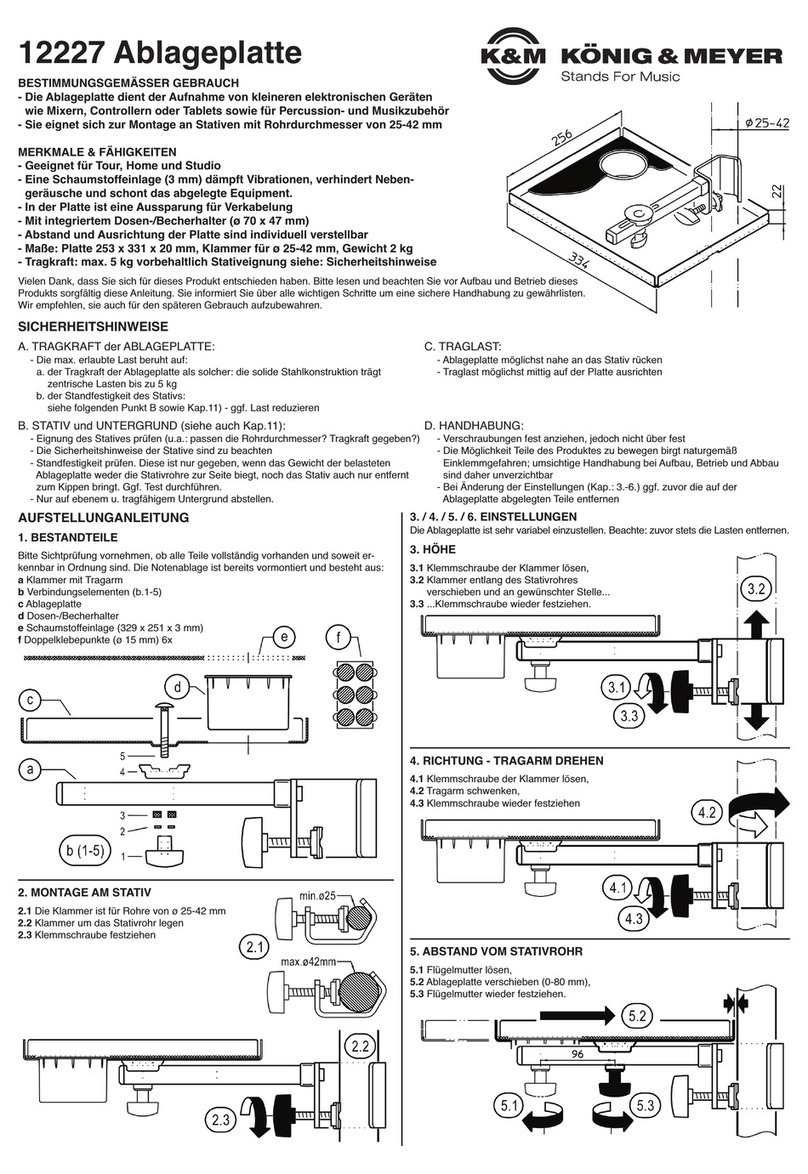
18815 Laptophalterung
- für K&M-Keyboardtische 18810, 18950 & 18953
- Position sehr flexibel einstellbar in:
-- Höhe - Richtung - Abstand - Neigung
- Anschlußbuchsen am Laptop sind stets frei zu-
-gänglich dank verstellbarer Anschlagstifte
- Auflagefläche: Höhe 240 mm x Breite 356 mm
SICHERHEITSHINWEISE
- Nur für Laptops und Manuskripte
- Grundsätzlich auf feste und ordnungsgemäße
-Verschraubungen achten.
- Klemmprisma 10 darf nur mit Schlitzen nach
-unten montiert werden.
- Neigung der Auflageplatte durch Einrasten der
-Streben fixieren.
- Anschlagstifte 15 so platzieren, dass
-Laptop sicher gehalten wird.
- Nur für K&M-Keyboardtische
-18810, 18950 & 18953
AUFBAUANLEITUNG
BESTANDTEILE
11Laptophalterung
12Gewindestift M6 x 8 mm
13Verstellrohr
14Klemmschraube M6 x 20 mm
153 x Klemmmutter M6 groß
16U-Scheibe ø 6,4 mm
172x Schloßschraube M6 x 20 mm
18R-Prisma (rechts - 1 x schwarz, 1 x grau)
19L-Prisma (links - 1 x schwarz, 1 x grau)
10 Klemmprisma mit Schlitz
11 Auslegerrohr mit Prisma
12 Sechskantschraube M6 x 40 mm
13 2 x U-Scheibe ø 5,3 mm
14 2 x Klemmmutter M5 klein
15 2 x Anschlagbolzen M5
16 2 x Kappe
MONTAGE
A. Befestigung am K&M-Stativ 18810 »Omega«
1R-Prisma 8und L-Prisma 9werden nicht gebraucht:
1bitte aussortieren.
2Die Laptophalterung kann an jedem der beiden seitlichen
2Rohre befestigt werden.
3Schloßschrauben M6 x 20 mm 7durch die Vierkantlöcher
3des Auslegerohrs 11 stecken und die Klemmmuttern 5.1
3kurz aufschrauben Winkel des Auslegerrohrs 11 an das
3Standrohr des »Omega« halten und den losen Klemmwinkel
310 innen von oben über die Schrauben schieben.
3Klemmmuttern 5.2 anziehen.
4Der Klemmspalt zwischen dern angezogenen Winkeln
4sollte ca. gleich groß sein.
B. Befestigung an K&M-Tischen 18950 & 18953
1R-Prisma 8und L-Prisma 9werden gebraucht um die
1Laptophalterung an den schrägen Füßen der Stative
1immer in waagerechter Position zu montieren.
1HINWEIS: Die Modelle 18950/18953-000-55 benötigen die
1schwarzen, 18950/18953-017-55 die grauen Prismen.
2Das Auslegerrohr der Halterung kann an jedem der 4
2Standbeine befestigt werden und zeigt je nach Wunsch im
245°-Winkel nach vorne bzw. hinten.
3Dadurch ergeben sich acht mögliche Positionen der
3Laptophalterung.
4WICHTIG: die Prismen 8, 9können nicht beliebig ein-
4gesetzt werden, sondern müssen in entsprechender Art
4und Weise positioniert werden. Siehe Fig. 2-3-4.
5Beide Prismen (richtige Positionen raussuchen) in die
5jeweiligen Winkel clipsen.
6Halterung an Standbein schrauben: dazu siehe oben A.3.
6der Vorgang ist der gleiche, nur eben mit den Prismen
68, 9zum Ausgleich der schrägstehenden Füße.
Vielen Dank, dass Sie sich für dieses Produkt entschieden haben.
Diese Anleitung informiert Sie über alle wichtigen Schritte bei Aufbau
und Handhabung. Wir empfehlen, sie auch für den späteren Gebrauch
aufzubewahren.
KÖNIG & MEYER GmbH & Co. KG
Kiesweg 2, 97877 Wertheim, www.k-m.de
18815-000-55 Rev.20 03-80-301-00 3/17
K&M 18810
Keyboardtisch
»Omega«
K&M
Keyboard-
Klapptische
18950-000-55
18953-000-55
K&M
Keyboard-
Klapptische
18950-017-55
18953-017-55
1
1
5
432
234
schwarz für
18950-000-55
und
18953-000-55
grau für
18950-017-55
und
18953-017-55

PRÜFEN, INSTANDHALTEN, REINIGEN
- bei Wartungsarbeiten auf evtl. Gefährdungen achten
- zur Reinigung am besten ein leicht feuchtes Tuch und ein nicht scheuerndes Reinigungsmittel benutzen.
FEHLERSUCHE (F) und BESEITIGUNG (B)
F: Installation wackelt. B: Überprüfen ob die Teile richtig angeordnet und die Gewinde fest angezogen sind.
B. Ordnungsgemäßen Aufbau der Keyboardstative überprüfen.
F: Ausleger- u. Verstellrohr steht nicht in waagerechter Stellung B: Prismen R, L neu justieren; siehe Kapitel MONTAGE B.1-6.
F: (Fehler kann nur bei 18950/53 auftreten).
TECHNISCHE DATEN / SPEZIFIKATIONEN
Material
Rohre, Platte: Stahl, pulversbeschichtet schwarz
Schrauben, Scheiben: Stahl verzinkt, Fiber
Kunststoffteile: PA, PE, schwarz / grau
Abmessungen Platte: 355 mm breit, 240 (253) mm hoch, Auslage: 270-430 mm, Höhe: 316 mm
Gewicht 1,95 kg
Verpackung L x B x H: 440 x 340 x 35 mm
MONTAGE
C. Laptophalterung an Auslegerrohr montieren
1Verstellrohr 3über Auslegerrohr 11 schieben und mittels
1der Teile 5,6,12 miteinander verschrauben.
2Bolzen der Laptophalterung 1in die Aufnahme
2des Verstellrohres 3stecken und diese Ver-
2bindung durch Eindrehen des Gewindestiftes 2
2sichern. Dieser Stift sollte so tief eingedreht
2werden, dass sich die Laptophalterung 1in der
2Bohrung zwar noch drehen, aber nicht mehr
2herausziehen lässt. Anschließend die Klemm-
2schraube 4einschrauben.
3Anschlagbolzen der Auflageplatte montieren:
3- Anhand des Laptops die geeigneten Stellen
3-(je 10 auf beiden Seiten) für die Anschläge
3-festlegen.
3- Bolzen 15 durch die entsprechenden Bohrungen
3-stecken und mit U-Scheibe 13 und Klemm-
3-mutter 14 verschrauben.
3- Kappen 16 auf Bolzen stecken.
BENUTZERHINWEISE / FUNKTIONEN / ABMESSUNGEN
EINSTELLUNGEN
D. HÖHE
1Klemmmuttern 5leicht lösen
2Halterung in gewünschte
2Position schieben.
3Anschließend Klemmmuttern 5
3wieder fest anziehen.
1 2 3
E. RICHTUNG
1Klemmschraube 4leicht lösen und
1Laptophalterung 1in gewünschte
1Richtung drehen.
2Klemmschraube 4wieder festdrehen.
F. ABSTAND
1Klemmmutter 5leicht lösen und
1Halterung 1in gewünschte Position
1schieben.
2Klemmmutter 5wieder festdrehen.
G. NEIGUNG
1Einstellbare Winkel (8 Varianten)
10°-6°-10°-14°-18°-22°-26°-30°
2Flügelschraube 1.a lösen bis der
2Querbolzen im Schlitz nach oben
2oder unten bewegt werden kann.
3Durch Anziehen der Flügelschraube
31.a wird der gewünschte Neigungs-
3winkel der Platte eingestellt. Es ist
3darauf zu achten, dass der
3Querbolzen in der jeweiligen
3Aussparung anliegt.
D
E
G
F
1 2 3

18815 Laptop holder
- for K&M-Keyboard Stands 18810, 18950 & 18953
- Position highly adjustable:
-- Height - Direction - Distance - Angle
- Laptop connectors are easily accessible
-thanks to the adjustable holding pins
- Holder dimensions Height 240 mm x Width 356 mm
SAFETY NOTES
- Only for laptops and manuscripts
- Ensure that the screws are in the proper
-position and tightened.
- Clamp prism 10 may only be installed with the
-slits facing downwards.
- Set the angle of the holder mount by clicking it
-into the struts.
- Holding pins 15 are to be placed so that the
-laptop is secure.
- Only for K&M Keyboard Stands
-18810, 18950 & 18953
SET UP INSTRUCTIONS
COMPONENTS
11Laptop holder
12Threaded pin M6 x 8 mm
13Adjustable tube
14Clamp screw M6 x 20 mm
153 x Clamp nuts M6 large
16Washer ø 6,4 mm
172 x Carriage bolts M6 x 20 mm
18R-Prism (right - 1 x black, 1 x gray)
19L-Prism (left - 1 x black, 1 x gray)
10 Clamp prism with slit
11 Extension tube with prisma
12 Hexagon socket screw M6 x 40 mm
13 2 x Washer ø 5,3 mm
14 2 x Clamp nuts M5 small
15 2 x Pin bolts M5
16 2 x Caps
ASSEMBLY
A. Mount to the K&M-Stand 18810 »Omega«
1R-Prism 8and L-Prism 9are not needed:
1place them aside.
2The laptop holder can be mounted to any of the side
2tubes.
3Place the carriage bolts M6 x 20 mm 7through the
3hexagon holes of the extension tube 11 and screw on the
3clamp nuts 5.1. Hold the bracket of the extension tube
311 to the »Omega« stand tube and loosen the clamp
3bracket 10 and place it over the screw.
3Tighten the clamping nuts 5.2.
4The clamp space between the tightened brackets should
4be approx. the same size.
B. Mount to K&M-Stands 18950 & 18953
1R-Prism 8and L-Prism 9are needed to mount the
1laptop holder in the horizontal position on the oblique feet
1of the stands.
1Note: The models 18950 / 18953-000-55 require the
1black, 18950 / 18953-017-55 the gray prisms.
2The extension tube of the holder can be mounted to each
2of the 4 legs and the angle can be 45° towards the front
2or the back.
3As such there are eight different laptop holder positions.
4NOTE: the prisms 8, 9cannot be used in contradiction to
4the instructions, rather they must be positioned according
4to the instructions. See Fig. 2-3-4.
5Both prisms (select the proper positions) are clipped to
5the respective bracket.
6Screw the holder to the leg: See A.3 above
6The steps are repeated only with prisms 8, 9to balance
6the angled legs.
Thank you for choosing this product. The instructions provide directions to
all of the important set up and handling steps. We recommend you keep
these instructions for future reference.
KÖNIG & MEYER GmbH & Co. KG
Kiesweg 2, 97877 Wertheim, www.k-m.de
18815-000-55 Rev.20 03-80-301-00 3/17
1
1
5
432
234
K&M 18810
Table-style
keyboard stand
»Omega«
K&M
Table-style
keyboard stand
18950-000-55
18953-000-55
K&M
Table-style
keyboard stand
18950-017-55
18953-017-55
black for
18950-000-55
and
18953-000-55
gray for
18950-017-55
and
18953-017-55

CHECK, MAINTENANCE, CLEANING
- In the event of workstation maintenance pay attention to possible risks.
- To care for the product use a damp cloth and a non-abrasive cleaning agent.
FAULT-FINDING (F) and REPAIR (R)
F: Installation is not stable. R: Check to see if the parts are in the right positions and the screws are properly tightened.
R. Check to see that the keyboard stand is properly setup.
F: Extension and adjustment tubes are not level R: Prismas R,L, need to be readjusted, see Section ASSEMBLY B.1-6.
F: (This can only happen with 18950/53).
TECHNICAL DATA
Material
Tubes, holder: Steel, powder coating, black
Screws, disks: Steel, galvanized, fiber
Plastic parts: PA, PE, black / grey
Dimensions Holder: 355 mm wide, 240 (253) mm high, extension: 270-430 mm, height: 316 mm
Weight 1.95 kg
Packaging L x W x H: 440 x 340 x 35 mm
ASSEMBLY
C. Mount the laptop holder to the extension arm
1Place the adjustment tube 3over the extension tube
111 and screw them together using parts 5, 6, 12.
2The laptop holder bolts 1are placed in the holes on the
2adjustment tube 3and this connection is secured by
2screwing in the threaded pin 2into the holes- This pin
2should be screwed in so far that the laptop
2holder pin 1can be placed into the hole but can
2no longer be pulled out. Then screw in clamping
2screws 4.
3Mount the pin bolts to the mounting plate:
3- Based on the laptop determine the correct
3-spots (10 on both sides) for the pins.
3- Place the bolts 15 in the corresponding holes
3-and screw together with the U disk 13 and
3-clamp nut 14.
3- Place the caps 16 on the bolts.
USAGE NOTES / FUNCTION / DIMENSIONS
ADJUSTMENTS
D. HEIGHT
1Slightly loosen the clamp nut 5.
2Place the holder in the desired
2position.
3Then re-tighten clamp nut 5.
1 2 3
E. DIRECTION
1Slightly loosen the clamp screw 4
1and place the laptop holder 1in the
1desired position.
2Tighten the clamp screws 4.
F. DISTANCE
1Slightly loosen the clamp nut 5and
1place the holder 1in the desired
1position.
2Tighten the clamp nut 5.
G. ANGLE
1Adjustable angle (8 positions)
10°-6°-10°-14°-18°-22°-26°-30°
2Loosen finger screw 1.a until the pin
2in the slot can be moved upwards
2and downwards.
3By tightening finger screw 1.a the
3desired angled of the holder is
3adjusted. Please ensure that the
3bolt is properly placed in to the
3slots.
D
E
G
F
1 2 3
Table of contents
Languages:
Other Konig & Meyer TV Mount manuals
