Kontron SYMKLOUD MS2900 User manual

» Quick Start Guide «
www.kontron.com
Kontron SYMKLOUD MS2900 Platform
Document revision 1.2

2
www.kontron.com
Quick Start Guide
» Table of Contents «
1Before Getting Started .......................................................................................................................4
1.1 About this Guide...................................................................................................................4
1.2 Equipment Needed to Set-up the System....................................................................................4
2Getting Started.................................................................................................................................6
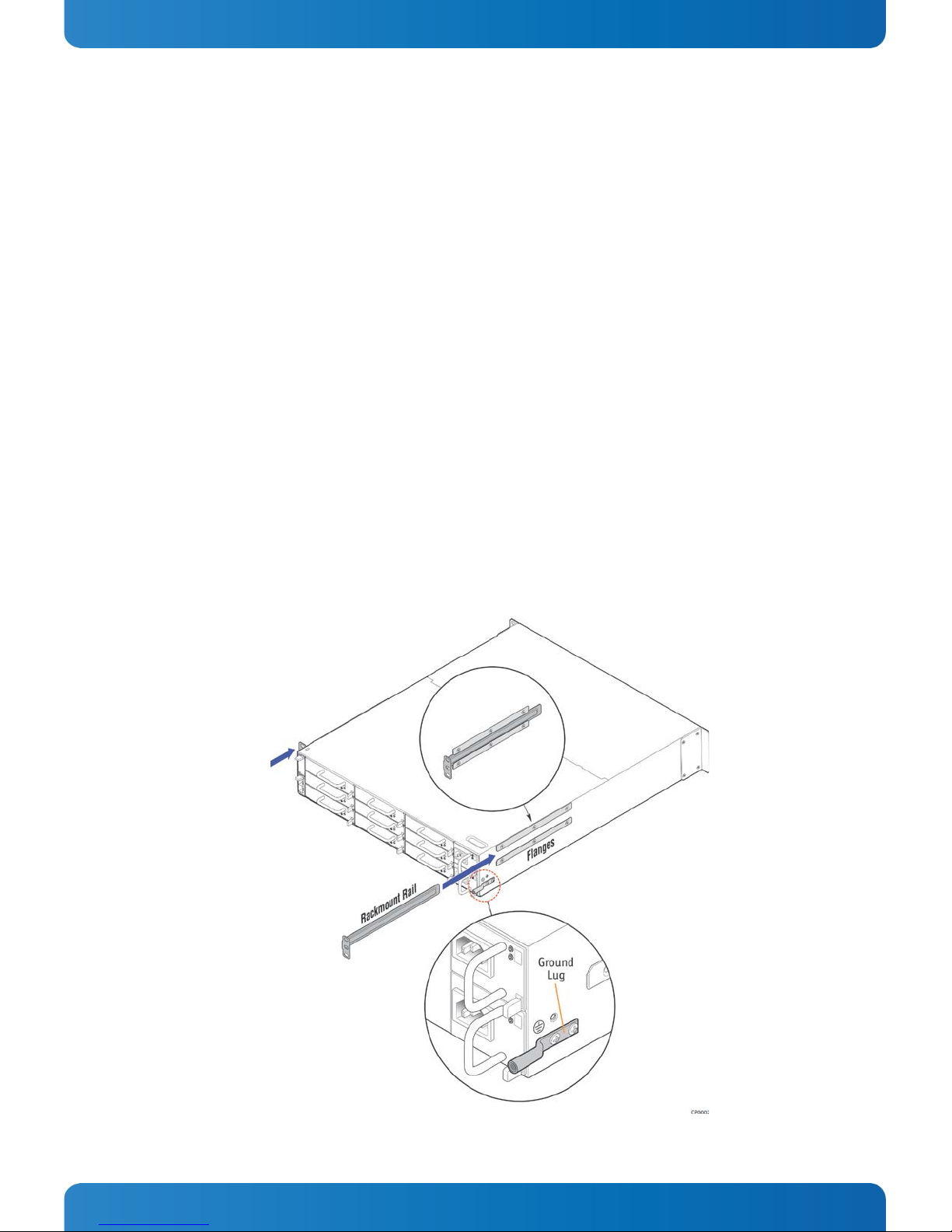
2.1 Preparing the System for Cabinet/Rack Installation......................................................................6
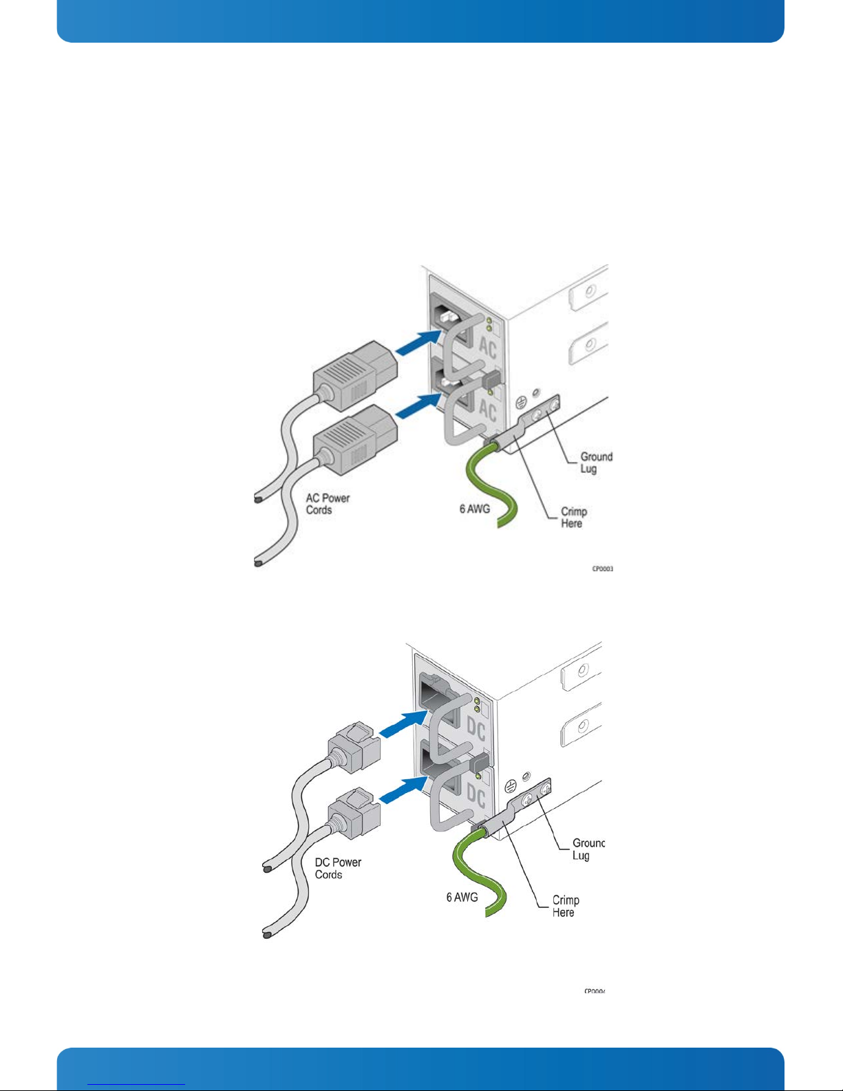
2.2 Connecting Power Cords .........................................................................................................7
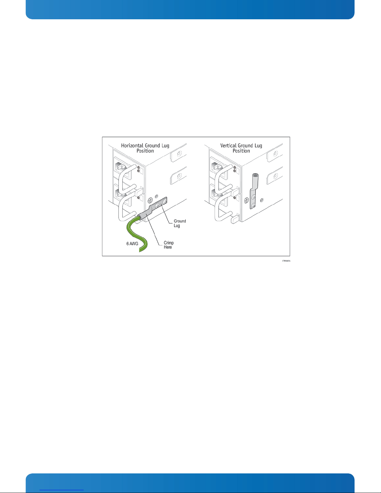
2.3 Connecting the Grounding Lug ................................................................................................8
2.4 Connecting I/O Cables ...........................................................................................................9
3First Power-Up................................................................................................................................ 11
3.1 Normal Behavior................................................................................................................. 11
3.2 Unexpected Behavior (Troubleshooting).................................................................................. 11
3.3 Health and Status Indicators ................................................................................................. 12
4Basic Configuration ......................................................................................................................... 13
4.1 Configuring the System Network ............................................................................................ 13
Using Management Networking ............................................................................................ 144.1.1
Using the Serial Console ..................................................................................................... 164.1.2
5Getting started with System Monitor ................................................................................................... 18
5.1 Login ............................................................................................................................... 18
5.2 System Monitor dashboard.................................................................................................... 19
5.3 Other System Monitor features............................................................................................... 19
5.4 API Features ...................................................................................................................... 19
6Running an Operating System ............................................................................................................ 20
6.1 First Boot-Up ..................................................................................................................... 20
6.2 BIOS Configuration ............................................................................................................. 20
7Additional Resources ....................................................................................................................... 21
7.1 MS2900 Platform Documentation ........................................................................................... 21
7.2 Contact Information............................................................................................................ 21
Technical Support.............................................................................................................. 217.2.1
8Trademarks and Copyright................................................................................................................. 22
8.1 Copyright Notice................................................................................................................. 22
8.2 Quality Standards ............................................................................................................... 22

3
www.kontron.com
Quick Start Guide
» Table of Figures «
Figure 1: Components for Initial Set-Up ................................................................................................5
Figure 2: Attaching the Slide Rails to the Chassis ....................................................................................6
Figure 3: Connecting the AC Power Cord and Grounding Cable....................................................................7
Figure 4: Connecting the DC Power Cord and Grounding Cable....................................................................7
Figure 5: Grounding Lug Positions .......................................................................................................8
Figure 6: MS2900 Front I/O Connections ...............................................................................................9
Figure 7: RJ-45 to DB-9 Console Adapter............................................................................................. 10
Figure 8: MS2900 Rear I/O Connections .............................................................................................. 10
Figure 9: MS2900 Front and Rear LEDs................................................................................................ 12
Figure 10: Management IP Addresses ................................................................................................. 14
Figure 11: Hub and Processor Node Port Mapping ................................................................................. 15
Figure 12: System Monitor Login Page ................................................................................................ 18
Figure 13: System Monitor Main Page ................................................................................................. 19

4
www.kontron.com
Quick Start Guide
1Before Getting Started
Caution! The SYMKLOUD MS2900 Platform is ESD-sensitive (electrostatic discharge) equipment. Users must
observe precautions for handling ESD-sensitive devices. Also, be sure to read the “Safety Instructions” section, in
Chapter 3 of the
SYMKLOUD MS2900 Platform User’s Guide
before handling the equipment.
1.1 About this Guide
This Quick Start Guide will assist with getting up and running with the SYMKLOUD MS2900 Platform. The guide
addresses the following tasks:
»Setting up the system and powering it on
»Using the system management configuration features
»Accessing the nodes’ serial consoles
»Accessing the System Monitor (web interface)
For more detailed information on these topics or additional features of the MS2900 platform, see all the available
documentation and select what is needed on the Kontron portal at http://cbu.kontron.ca/
NOTE: To ensure the latest information is being used, check the publication dates and version numbers of the
documentation against those available on the portal.
1.2 Equipment Needed to Set-up the System
Figure 1 shows the components and accessories required to get started. For instructions on how to install these
components, see Chapter 2:”Getting Started”.
Depending on the ordered configuration of the SYMKLOUD MS2900 system, various cables, accessories, or spare
components may be included in the shipment. For purposes of accomplishing the tasks described in this guide,
aimed at getting the system up and running, only the following items from the box are needed:
»The MS2900 system with any protective plastic or Styrofoam packaging removed
»The two rails that attach to the system chassis so it can be mounted in a cabinet/rack
»The RJ-45 to DB-9 adapter (used with a straight RJ45 cable) for console connection
The following equipment may also be needed:
»Standard, straight RJ-45 cable (CAT5 or better)
»An Internet connection
»The power cord(s) for the system: AC or DC, according to what was ordered, in the (default) single power supply
configuration or the (optional) redundant power supply configuration
NOTE: Each DC power supply ships with a DC mating connector which must be crimped to an appropriate cable and
attached to the rear panel before powering up the platform. Instructions on how to wire the provided DC mating
connector can be found in the Symkloud MS2900 User’s Guide.

5
www.kontron.com
Quick Start Guide
Figure 1: Components for Initial Set-Up

6
www.kontron.com
Quick Start Guide
2Getting Started
This chapter covers how to set up the MS2900 platform for installation in a cabinet/rack and how to connect the
cables.
2.1 Preparing the System for Cabinet/Rack Installation
The MS2900 platform comes with both front and rear mounting attachments. The front of the chassis has brackets
attached on each side for fastening the system in a cabinet/rack. The system also comes with two slide rails to
enable mounting at the rear of the cabinet/rack.
NOTE: Because the heaviest components in the chassis, i.e., the processor nodes and power supplies are at the
rear, using the slide rails and L-brackets for rear mounting is mandatory. This method will provide the most stable
and secure cabinet/rack installation.
The system has rear mounting flanges for the rails already in place on both sides of the chassis. No screws are
needed; just slide the rails between the flanges, with the L-bracket facing the rear of the chassis, as shown in
Figure 2.
Depending on the width of the cabinet or rack used, the grounding lug on the left rear side of the chassis may
make this a tight fit. If the chassis can’t be easily slid into place, it may become necessary to angle or wiggle the
chassis to get it into the rack. If unsuccessful, remove the grounding lug by unscrewing the two fasteners and re-
attach it from the rear of the cabinet/rack once the chassis is in place. See Section 2.3:”Connecting the Grounding
Lug” for possible positions for installing the grounding lug.
Figure 2: Attaching the Slide Rails to the Chassis

7
www.kontron.com
Quick Start Guide
2.2 Connecting Power Cords
NOTE: When using a rack, do not install the power cord(s) until after the system is completely mounted in the
rack.
Power cords should be connected to the MS2900 platform as shown in Figure 3 and Figure 4.MS2900 systems with
DC power supplies ship the parts for assembling a power cord. Instructions on how to wire the provided DC mating
connector can be found in the Symkloud MS2900 User’s Guide.
Figure 3: Connecting the AC Power Cord and Grounding Cable
Figure 4: Connecting the DC Power Cord and Grounding Cable

8
www.kontron.com
Quick Start Guide
2.3 Connecting the Grounding Lug
In addition to plugging in the power cord, the grounding lug on the chassis’ lower right side (viewed from the
rear) must be used with DC power supplies (optional for AC power) and connected to earth ground for proper
safety grounding of the chassis enclosure.
The grounding lug can be positioned horizontally (parallel with the chassis’ side) or vertically (pointing toward
the top-cover of the chassis). Both possibilities are shown below.
Figure 5: Grounding Lug Positions

9
www.kontron.com
Quick Start Guide
2.4 Connecting I/O Cables
The MS2900 platform provides I/O connections from both the front and rear of the chassis. There are up to two
10GbE uplink ports, two 10GbE stacking uplink ports, and eight 1GbE RJ-45 LAN ports (four for each Hub Module,
front access only
) in the system. For each hub there is also front panel access for an RJ-45 console port and a
management RJ-45 port.
Figure 6: MS2900 Front I/O Connections
I/O Port Description
1
Management 1GbE RJ-45 port (Switch/ShMC 1)
(Marked ‘’MNGT’’ on the Hub 1 faceplate)
2
Console RJ-45 port (Switch/ShMC 1)
3
10GbE SFP+ stacking port (Switch/ShMC 1)
(Marked ‘’1’’ on the Hub 1 faceplate)
4
10GbE SFP+ uplink port (Switch/ShMC 1)
(Marked ‘’2’’ on the Hub 1 faceplate)
5
Quad 1GbE RJ-45 ports (Switch/ShMC 1)
(Marked ‘’3’’, ‘’4’’, ‘’5’’ and ‘’6’’ on the Hub 1 faceplate)
6
Management 1GbE RJ-45 port (Switch/ShMC 2)
(Marked ‘’MNGT’’ on the Hub 2 faceplate)
7
Console RJ-45 port (Switch/ShMC 2)
8
10GbE SFP+ stacking port (Switch/ShMC 2)
(Marked ‘’1’’ on the Hub 2 faceplate)
9
10GbE SFP+ uplink port (Switch/ShMC 2)
(Marked ‘’2’’ on the Hub 2 faceplate)
10
Quad 1GbE RJ-45 ports (Switch/ShMC 2)
(Marked ‘’3’’, ‘’4’’, ‘’5’’ and ‘’6’’ on the Hub 2 faceplate)
For information about port mapping for the 10GbE and 1GbE connections, see Figure 11 in the “Configuring
Switches subsection under Section 4.1.1.

10
www.kontron.com
Quick Start Guide
The MS2900 platform ships with an RJ-45 to DB-9 adapter (shown below) included in the box. Use this adapter
with a straight RJ45 cable connected to the console port on the front of the Active Hub Module’s faceplate (see
callouts 2 and 7 in Figure 6). The Active Hub can be identified by the solid-green status LED on its faceplate (the
Standby Hub’s status LED will blink).
Figure 7: RJ-45 to DB-9 Console Adapter
Figure 8 shows the location of the two 10GbE uplink ports and two 10GbE stacking ports (one of each per
switch/ShMC hub), when the optional MSU8700 Rear uplink modules are used.
Figure 8: MS2900 Rear I/O Connections

11
www.kontron.com
Quick Start Guide
3First Power-Up
This chapter covers what to expect when booting up the system for the first time. Both normal and unexpected
conditions are described and troubleshooting tips are provided.
At initial power up, pressing the power button is not necessary: simply connect the power cord(s).
Once the system is on, pressing the power button triggers a clean shutdown or standby event on any active nodes.
The inactive shelf manager can also go to standby state or off. Holding the power button for four seconds
immediately offlines all nodes.
Using the System Monitor is the fastest way to bring up the system, including configuration of the network and
nodes. For information about connecting to the System Monitor for the first time, see section 5:”Getting started
with System Monitor”.
For information about using other access methods, see the
SYMKLOUD MS2900 Platform User’s Guide
.
3.1 Normal Behavior
The normal behavior after initial power up is defined as follows:
1. As soon as power is applied to the unit, the fans begin turning at full speed.
2. Each processor nodes will have their ID LED ‘ON’ (solid-blue) at the rear of the chassis
3. The front panel chassis ID LED will also be ‘ON’ (solid-blue).
4. After a few seconds, the hub(s) start booting up:
- Hub 1 (left side): power LED goes ‘ON’ (green) to indicate the active ShMC.
- Hub 2 (right side - if installed): power LED blinks green to indicate the standby ShMC.
5. The fan manager on the ShMC takes control of the fans, slowing their speed.
6. The processor nodes start booting up:
- Each node’s ID LED changes from ‘ON’ (solid-blue) to ‘OFF’, indicating the node payload has been
powered-on.
- The power LED goes from ‘OFF’ to ‘ON’ (green), indicating the payload power is active.
7. Other platform components finish booting up and the switches, shelf managers, and processor nodes can
now be interacted with.
3.2 Unexpected Behavior (Troubleshooting)
The following conditions, while unlikely, could possibly occur:
»A processor node ID LED remains ‘ON’ (solid-blue).
»A hub ID LED remains ‘ON’ (solid-blue).
»A fan LED is on (amber), indicating a fan fault.
»Fans speed up to the maximum level and stay there; The fan manager on the ShMC does not slow them down.
The manufacturing site checks for the presence of these conditions when the unit is built and ensures they are not
occurring when the MS2900 platform is prepared for shipment. If any of these problems or other unexpected
conditions are encountered, contact Kontron Support for assistance to diagnose/resolve the issue and continue
working with the system.
NOTE: If a power failure occurs, the system automatically reboots when power is restored and goes through the
normal steps as described in Section 3.1.

12
www.kontron.com
Quick Start Guide
3.3 Health and Status Indicators
This section covers all of the LEDs on the MS2900 platform, present on the following components: the hubs’
faceplates, the front panel, rear uplink modules, the node sleds, and the power supplies. Figure 9 shows the LED
locations in detail.
Figure 9: MS2900 Front and Rear LEDs

13
www.kontron.com
Quick Start Guide
4Basic Configuration
This chapter covers the following topics:
»Configuring the system network
»Configuring the system nodes
There are a few different ways to do the basic system configuration. The subsections in this chapter cover the
various methods.
Tasks/topics the System Monitor covers are:
»Checking system status
»Upgrading software
Once logged in, the System Monitor presents a system inventory page with all node configuration information. For
more information about System Monitor’s features, refer to the “SYMKLOUD System Monitor User’s Guide”.
4.1 Configuring the System Network
The MS2900 platform must be configured for the specific network environment targeted. There are two different
ways to access the system components and tailor the networking configuration:
»Using management networking, as shown in Section 4.1.1
»Using the serial console, as shown in Section 4.1.2

14
www.kontron.com
Quick Start Guide
Using Management Networking4.1.1
Each device on the MS2900 platform comes pre-configured with a management IP address. The System Monitor
displays a list of each device including its management IP address. For help accessing the System Monitor, see
section 5: “Getting started with System Monitor” For more information about the System Monitor’s features, refer
directly to the “SYMKLOUD System Monitor User’s Guide”.
Figure 10 shows the default IP addresses for the Hub Module and the processor nodes.
Figure 10: Management IP Addresses
To configure the MS2900 system, the external equipment (e.g., a laptop) should be configured to use the same
subnet as the MS2900 platform, and be connected via the RJ-45 management port (leftmost, marked “MNGT” on
the hub faceplate) on the active hub; This is a 10/100/1000 Mbit connection.
Configuring Processor Nodes
Connect to the nodes via the serial connection (see Section 4.1.2), SSH, or initiate a KVM session from the System
Monitor to access their serial console interface (shell).
Once the processor nodes are configured, configure the fabric GbE interfaces to meet any specific needs.

15
www.kontron.com
Quick Start Guide
Configuring Switches
Type in the pre-configured master switch IP address 192.168.10x.10 (Figure 10, footnote 2) in the external
equipment’s web browser to access the switches’ SMBStaX™ GUI.
Figure 11 shows the port mapping for the switch.
Figure 11: Hub and Processor Node Port Mapping
On both Hub #1 and Hub #2, port 2 (labeled ’’2’’ on each hub’s faceplate) is the 10GbE uplink port. These ports are
identified in the iCLI as 1/2 and 2/2, respectively.
On both Hub #1 and Hub #2, port 1 (labeled ’’1’’ on the hubs’ faceplate) is for stacking multiple SYMKLOUD
MS2900 systems. These ports are identified in the iCLI as 1/1 and 2/1, respectively. They are not shown in certain
views of the SMBStaX™ GUI when stacking is enabled.
If the MS2900 system is equipped with the optional MSU8700 rear uplink modules:
-Stacking is performed using port 1 of each uplink module (marked on the faceplate), which is routed to
switch port #1.
-A 10GbE uplink port is available on port 2 of each uplink module (marked on the faceplate) and routed to
switch port #2.
NOTE: In the SMBStaX™ GUI, ports #1 and #27 are not visible in the default configuration since they are used for
stacking.
Chassis slots 7 and 9 have 10GbE pipes to support up to two 10G processor nodes:
-Hub 1, port #22 (node 7 fabric 1)
-Hub 2, port #24 (node 9 fabric 2)
All other ports are 1GbE.

16
www.kontron.com
Quick Start Guide
Using the Serial Console4.1.2
The MS2900 platform’s components can be accessed using the MSH8900 serial console multiplexer (MUX) as
follows:
1. Connect an RJ45 serial cable to the Active Hub’s (with the solid-green status LED) serial console port
(on the front of the MSH8900 - see “2” in Figure 6),
or use the RJ-45 to DB-9 adapter included and any straight RJ45 cable (Cat5 or better).
2. Run a VT100 terminal emulator with the following serial port communication parameters:
115200 baud
no parity
8 data bits
3. To switch the serial console between different system components(Hubs/Nodes),
press CTRL+g followed by the position ID of the component to be connected:
0: Shelf manager (ShMC) of the connected Hub Module*
1to 9: processor node 1 through node 9**
–(minus): CLI of the switch of the connected Hub Module*
For example, to direct the serial console to processor node 7, press CTRL g and then press 7.
4. To switch the serial console between different components on a Node (BMC/CPU),
hold CTRL and press g, g(abbreviated CTRL+g,g),followed by the component ID:
0: Node BMC’s ‘ipmitool>’ shell
1: Payload CPU 1
2: Payload CPU 2 (for Dual-CPU nodes only)
* These options (0-9, -) will always connect to the physical ShMC/Switch of the serial-connected Hub Module,
regardless of role (ShMC: Active/Standby or Switch: Master/Slave). Available functionality is limited from the
Standby ShMC and Slave Switch(es) in a chassis/stack.
** Node-serial access is only possible when physically connected to the Active Hub Module
Configuring Shelf Management Controllers (ShMCs)
Note:This is the same interface/IP used to access the System Monitor (web interface)
To connect the serial console MUX to a ShMC, follow these steps:
1. Press CTRL g and then press 0 to switch the console to the ShMC
2. Log in with user admin and password: admin
3. In root mode, use admin again for the password
The ipmitool> prompt should be displayed.
To instruct the BMC to obtain an IP address from an existing DHCP server, type:
lan set 1 ipsrc dhcp
or to use a static IP address, type the following commands:
1. lan set 1 ipsrc static
2. lan set 1 ipaddr 192.168.100.X
3. lan set 1 defgw ipaddr 192.168.100.X
4. lan set 1 netmask 255.255.255.X

17
www.kontron.com
Quick Start Guide
Configuring a Processor Node’s BMC from the ShMC
1. Switch the serial console MUX to address the target Processor node, by pressing CTRL g followed by the
Node’s slot number.
2. Press CTRL g,g followed by 0to access the BMC’s ipmitool> shell
To instruct the BMC to obtain an IP address from an existing DHCP server, type:
lan set 1 ipsrc dhcp
or to use a static IP address, type the following commands:
5. lan set 1 ipsrc static
6. lan set 1 ipaddr 192.168.100.X
7. lan set 1 defgw ipaddr 192.168.100.X
8. lan set 1 netmask 255.255.255.X
Configuring the interface IP of the switches
By default, the switch configuration web interface (SMBStaX) can be accessed via the MNGT Ethernet port at
address 192.168.10x.10, where “x” is the chassis ID. The “chassis ID” is always ‘1’, unless the switch is configured
for stacking with one or more chasses.
Follow the steps below to change the SMBStaX web interface IP:
1. Change the serial console MUX to address the switch (from the Master switch):
a. Press CTRL g and then press –(minus)
2. Login with user: admin and password: admin
a. If presented with a ‘Slave_x#’ prompt, you are connected to the switch with the ‘Slave’ role.
Connect your serial console cable to the serial port on the opposite Hub Module
3. Enter the configuration terminal by typing: configure terminal
4. Configure the interface IP address:
a. Type: interface vlan 4093
b. Set an IP address via:
i. DHCP, type: ip address dhcp
or
ii. static, type: ip address dhcp 192.168.10x.X 255.255.255.x
c. Type: end
5. To read the IP address obtained the DHCP server type: show interface vlan 4093

18
www.kontron.com
Quick Start Guide
5Getting started with System Monitor
Each SYMKLOUD hub runs an instance of the System Monitor web application; it is recommended to use the latest
version of Chrome to connect to the application.
To access the System Monitor from a web browser, enter the management IP (or shared IP, if configured) of the
"Active" Shelf Manager in the browser’s address bar. See section 4.1.1:”Using Management Networking” for the
default address (IOL IP address) of the Active ShMC.
It is also strongly recommended to configure and to connect to the "Shared IP" feature as described in the
“SYMKLOUD System Monitor Programmer's Guide”. The shared IP will always give access to the "Active" Shelf
Manager.
NOTE: The application refreshes the information shown on its pages every 5 seconds. Because of this, any change
to a state or value of a physical component of the current platform can take up to 5 seconds before being reflected
in the web application (e.g.: fan speeds, hotswap status, alarms or power consumption values).
5.1 Login
The System Monitor provides role-based user access for its API and web application. Upon first login, use the
following default credentials to access the application:
Username : admin
Password: admin
Figure 12: System Monitor Login Page
NOTE:You should change the admin password at the first login. Refer to the “System Monitor User’s Guide” for
details on how to modify the admin password. Once logged in, you can modify your password and perform other
management tasks.

19
www.kontron.com
Quick Start Guide
5.2 System Monitor dashboard
At login, you will be redirected to the "Dashboard" page, which provides (among others):
»links to the main sections of the application (System Monitoring, OneClick Upgrade, Remote Access, etc.)
»a graph of your platform(s)' power consumption
»a drop-down menu to access the CLI of your hubs/nodes
Figure 13: System Monitor Main Page
5.3 Other System Monitor features
The System Monitor includes many other features for managing the SYMKLOUD appliance, including (but not
limited to):
»Platform inventory (for the single system, or all systems in a Multi-Platform setup)
»Physical layout of hubs and nodes
»Power-control and monitoring of hubs and nodes
»Detailed firmware versions
»“One-click Upgrade” tool for applying new firmware to platform elements
»Remote access to payloads
»Fan speed monitoring and more
Refer to the “SYMKLOUD System Monitor User’s Guide” for additional explanations and details on features.
5.4 API Features
The SYMKLOUD System Monitor is built using a RestFul API running on the Shelf Manager. All of the data and
actions provided by the web interface are provided by this API. This allows you to create scripts to interact with an
individual platform or, in some cases, a cluster of platforms. Refer to the “SYMKLOUD System Monitor API
Programmer’s Guide” for additional details.

20
www.kontron.com
Quick Start Guide
6Running an Operating System
The SYMKLOUD MS2900 platform can be shipped with or without a pre-installed operating system.
If the system was ordered with a pre-installed OS on the processor nodes, supplementary instructions and
information to this Guide will have been included.
If the system was ordered without a pre-installed OS on the processor nodes, a supported OS will need to be
installed now.
Accessing Processor Nodes
The system payload varies depending on the application. Examples using generic access points and OS installation
tips are presented below:
For MSP8xxx processor nodes, use the serial port, IOL or a KVM/VM session to access the node OS.
6.1 First Boot-Up
If an operating system was pre-installed on the MS2900 platform, the processing nodes’ OS (if factory-installed by
Kontron) will have booted up as part of the power-up process.
6.2 BIOS Configuration
The BIOS configuration described below refers to x86 nodes and is Unified Extensible Firmware Interface (UEFI)
compatible.
To access the BIOS Menu:
1. Power on or reboot the node or system.
2. During POST (first output on the serial console), press the <F2> or <Del> key to enter the BIOS setup
The Setup default values are the optimum performance settings for all devices and system features; it is possible
to change some of the settings, namely the device boot order, as needed.
Refer to your Processor nodes’ User’s Guides for more details on default boot-order, etc.
Other manuals for SYMKLOUD MS2900
2
Table of contents
Popular Chassis manuals by other brands

MAXDATA
MAXDATA PLATINUM 5200 user manual

National Instruments
National Instruments cDAQ-9178 user manual

IBM
IBM 3453 Series Customer Install Guide

Svive
Svive Luna manual

National Instruments
National Instruments CompactRIO cRIO-FRC Operating instructions and specifications

Cisco
Cisco ASA5500-HW - Hardware Accessory Kit Network... Hardware installation guide