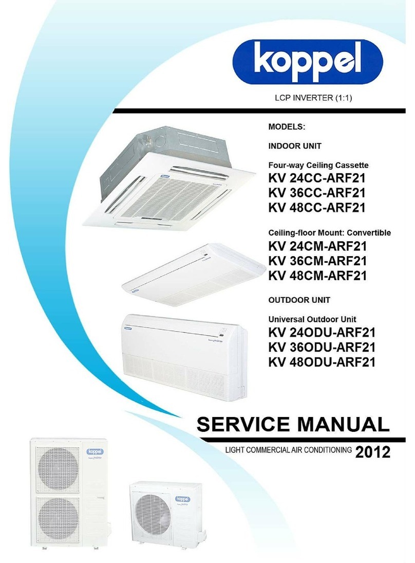
koppel KV 24CC-ARF21 User manual


Contents
CONTENTS
Part 1 General Information .................................................................................................... 1
Part 2 Indoor Units ................................................................................................................. 6
Part 3 Outdoor Units ............................................................................................................. 63
Part 4 Installation .................................................................................................................. 75
Part 5 Electrical Control System ....................................................................................... 103

General Information
Part 1
General Information
1. Model Lists ..................................................................................................2
2. External Appearance ..................................................................................3
2.1 Indoor Units ....................................................................................... 3
2.2 Outdoor Units .................................................................................... 3
3. Nomenclature ............................................................................................. 4
4. Features ...................................................................................................... 5
1

Model Lists
1. Model Lists
1.1 Indoor Units
R410A (capacity multiplied by 1000Btu/h)
Type Function 24 36 48 60
Four-way cassette Cooling √
Super-slim Four-way cassette Cooling √√
Ceiling & floor Cooling √
3rd generation ceiling & floor Cooling √√
Floor-standing Cooling √ √
Rotary DC Inverter GMCC KV24CC-ARF21
KV24CM-ARF21
KV36ODU-ARF21B Rotary DC Inverter MITSUBISHI
KV36CC-ARF21B
KV36CM-ARF21B
KV48ODU-ARF21B Rotary DC Inverter MITSUBISHI
KV48CC-ARF21B
KV48CM-ARF21B
1.2 Outdoor Units
Universal Outdoor unit Model Compressor type Compressor Brand Matched indoor units
KV24ODU-ARF21
2

3

Nomenclature
3. Nomenclature
3.1 Indoor / Outdoor Unit
K V 36 CM - A RF2 1 B
Revision
-:- - Blank (no revision)
A - First Revision
B - Second Revision
Series Code
Refrigerant
RF2 - R410A
Power supply
A - 220/1/60 C - 220/3/60
B - 380/3/60
Model Type
CC - Cassette Type FM - Floor mount
CM - Ceiling-floor ODU - Universal Outdoor Unit
Capacity (×1000Btu/h)
Compressor type
V - Inverter
Koppel
4

Features
4. Features
4.1 Universal outdoor unit design
Indoor unit with the same capacity as the outdoor unit can be matched.
4.2 High efficiency and energy saving.
Thanks to the DC inverter technology and optimized piping system, the EER and COP of whole
series can easily reach A-class.
4.3 Low noise and low starting current.
Thanks to the DC inverter technology, the system can work with low noise, and very small starting
current.
4.4 Intelligent refrigerant adjustment technology.
Throttle part is made up of capillary and electronic expansion valve (EXV). The outdoor unit can
output the most accurate capacity in any condition.
4.5 Working in cooling mode under -15℃.
Outdoor unit built-in with low ambient kit, it can control the outdoor unit’s fan and cooling can be
performed throughout the year for computer rooms, banquet halls, etc. Wide operation range
covers outdoor temperatures as low as -15℃for cooling.
4.6 Indoor & outdoor unit’s power supply is separate.
4.7 All indoor units have network control function.
4.8 All indoor units have Auto-restart function.
5

Indoor Units
Part 2
Indoor Units
Four-way Cassette Type ...................................................... 7
Super Slim Cassette Type .................................................. 20
Ceiling & Floor Type ........................................................... 33
3rd Generation Ceiling & Floor Type .................................. 45
Floor-standing Type ........................................................... 53
6

Four-way Cassette Type
Four-way Cassette T ype
1. Features .......................................................................................................... 8
2. Dimensions ................................................................................................... 11
3. Service Space ............................................................................................... 12
4. Wiring Diagrams ........................................................................................... 13
5. Capacity Tables ............................................................................................ 14
6. Air Velocity Distributions(Reference Data) ................................................ 15
7. Electric Characteristics ............................................................................... 16
8. Sound Levels ................................................................................................ 16
9. Accessories .................................................................................................. 17
10. The Specification of Power ....................................................................... 18
11. Field Wiring ................................................................................................. 19
7

Features
1. Features
(1) Low operation noise
—Streamline plate ensures quietness
—Creates natural and comfortable environment
(2) Efficient cooling——Equal, fast and wide range cooling
(3) Excellent performance. The optimal evaporator & sufficient airflow volume guarantees the excellent
capacity
(4) The adoption of the most advanced 3- Dimensional Screw fan
—Reduces the air resistance passing through
—Smoothes the air flow
—Makes air speed distribution to the heat exchange uniform
(5) Fresh air makes life healthier and more comfortable.
(6) Drainage pump can take up the condenser water up to 750mm.
(7) Ultra thin machine body for easy installation and maintenance. 24K:230mm.
8

Features
(8) Different color panels to be chosen: White、Gray、Blue、Black
(9) Swing angle of louver
1) Add one more swing motor, one motor drivetwo louvers. Controlling the interspace of each part,
minimizing the angle loss.
2) The swing angle of the first louver are 40~42 degrees and the second louver are 37~38 degrees.
New evaporator and inner configuration design can acquire high heat-exchanger effect.
(10) More strengthening rib design around the panel, preventing the distortion of the panel.
(11) New outlet frame design to make the phenomena of coagulation with great improvement: prevent the
condensing water from damaging the air guide strip.
(12) Adding rib on the panel of fan outlet, which can avoid the air outlet flow directly to people.
(13) 4 speeds available, optional super high fan speed design suitable for large building over 3m high.
(14) Adding digital tube displaying on the display board. LED can display the Error Code to make
malfunction checking easier.
9

Features
(15) Reserve spaces for air side-outlet, it is available to connect duct pipe hence air supplying from the four
sides to nearby small room..
(16) The connecting pipe and drop height is higher. Max. pipe length up to 50m(refer to ①), and Max. drop
height up to 30m(refer to ②).
(17) Optimal design, smaller Control Box, Space saving and convenient for wiring,
Using fire resistance galvanized steel for E-box material. Metal box make the control part more stable and
prevent damaging.
(18) New Panel optional: 360 degree air-outlet.
10

Dimensions
2. Dimensions
Unit: mm
MODEL A B C H
KV24CC-ARF21 230 Ф15.9 Ф9.52 >260
11

Service Space
3. Service Space
>1000mm
>1000mm
>1000mm
>1000mm
12

Wiring Diagrams
4. Wiring Diagrams
KV24CC-ARF21
13

Capacity Tables
5. Capacity Tables
5.1 Cooling Capacity
KV24CC-ARF21
Cooling Outdoor conditions (DB)
Indoor Conditions (kW) 21ºC 28ºC 35ºC 43ºC
21/15ºC DB/WB
TC 7.52 7.15 6.79 6.50
SC 5.56 5.51 5.43 5.46
Input 2.10 2.28 2.38 2.46
24/17ºC DB/WB
TC 7.74 7.37 7.01 6.57
SC 5.80 5.75 5.68 5.52
Input 2.23 2.38 2.49 2.61
27/19ºC DB/WB
TC 7.88 7.52 7.30 6.79
SC 5.83 5.79 5.69 5.57
Input 2.28 2.41 2.54 2.66
32/23ºC DB/WB
TC 8.03 7.74 7.59 7.01
SC 6.83 6.73 6.68 6.52
Input 2.38 2.49 2.66 2.76
Notes:
TC : Total capacity ; kW
SC: Sensible heat capacity ; kW
Input: Input power; kW
14

Air Velocity and Temperature Distributions (Reference Data)
6. Air Velocity Distributions (Reference Data)
Airflow velocity
15

Electric Characteristics
7. Electric Characteristics
Model Indoor Unit Power Supply
Hz Voltage Min Max MFA
KV24CC-ARF21 60 220-230 198 242 10
Note:
MFA: Max. Fuse Amps. (A)
8. Sound Levels
1.4m
Microphone
Model Noise level dB(A)
H M L
KV24CC-ARF21 42 40.5 39
16

Accessories
9. Accessories
Installation Fittings
Name Shape Quantity
Installation paper board
1
Tubing & Fittings Soundproof / insulation sheath(on
some models)
1
Drainpipe Fittings
Out-let pipe sheath(on some
models)
1
Out-let pipe clasp(on some models) 1
Drain joint(on some models) 1
Seal ring
Remote controller & Its
Frame
Remote controller & Its Frame 1
Remote controller holder 1
Mounting screw(ST2.9×10-C-H) 2
Remote controller manual 1
Alkaline dry batteries (AM4)
2
Others
Owner's manual 1
Installation manual 1
Installation accessory
(The product you have
might not be provided the
following accessories
Expansible hook
4
Installation hook 4
Orifice 1
17

The Specification of Power
10. The Specification of Power
Model KV24CC-ARF21
INDOOR UNIT POWER
Phase 1-phase
Frequency and
Voltage 220-230V, 60Hz
POWER WIRING
(mm2) 3×1.0
CIRCUIT BREAKER/
FUSE(A) 15/10
OUTDOOR UNIT POWER
Phase 1-phase
Frequency and
Voltage 220-230V, 60H
POWER WIRING
(mm2) 3X2.5
CIRCUIT BREAKER/
FUSE(A) 30/20
Indoor/Outdoor Connecting Wiring
(Weak Electric Signal) (mm2) 3×0.5
Indoor/Outdoor Connecting Wiring
(Strong Electric Signal) (mm2)
18
This manual suits for next models
11
Table of contents
Other koppel Air Conditioner manuals

koppel
koppel KV09WM-ARF31D Repair manual

koppel
koppel KPC-18H5 User manual

koppel
koppel KCM-18CHW User manual

koppel
koppel CS343U User manual

koppel
koppel KCM-18R1A User manual
koppel
koppel KFM-36E0C User manual

koppel
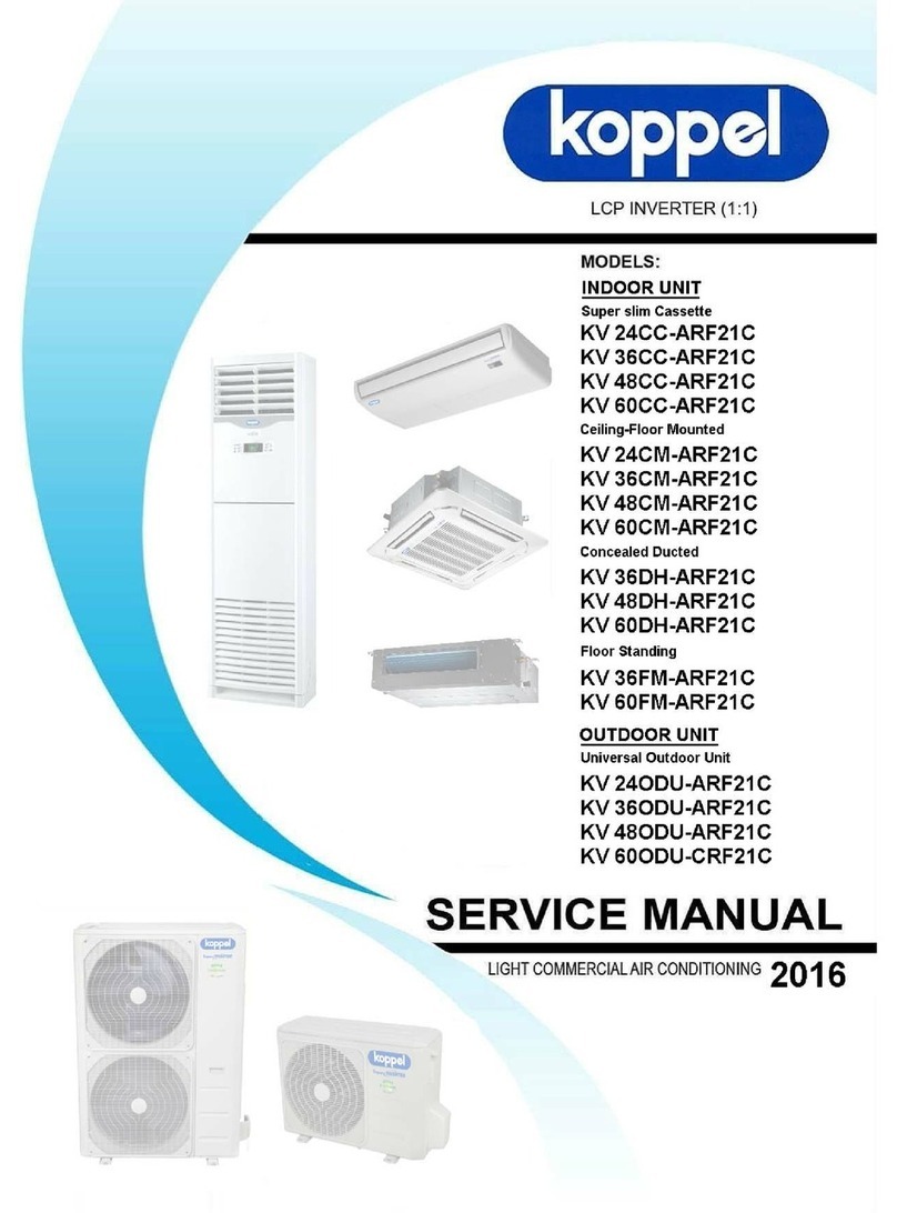
koppel KV24ODU-ARF21 User manual

koppel
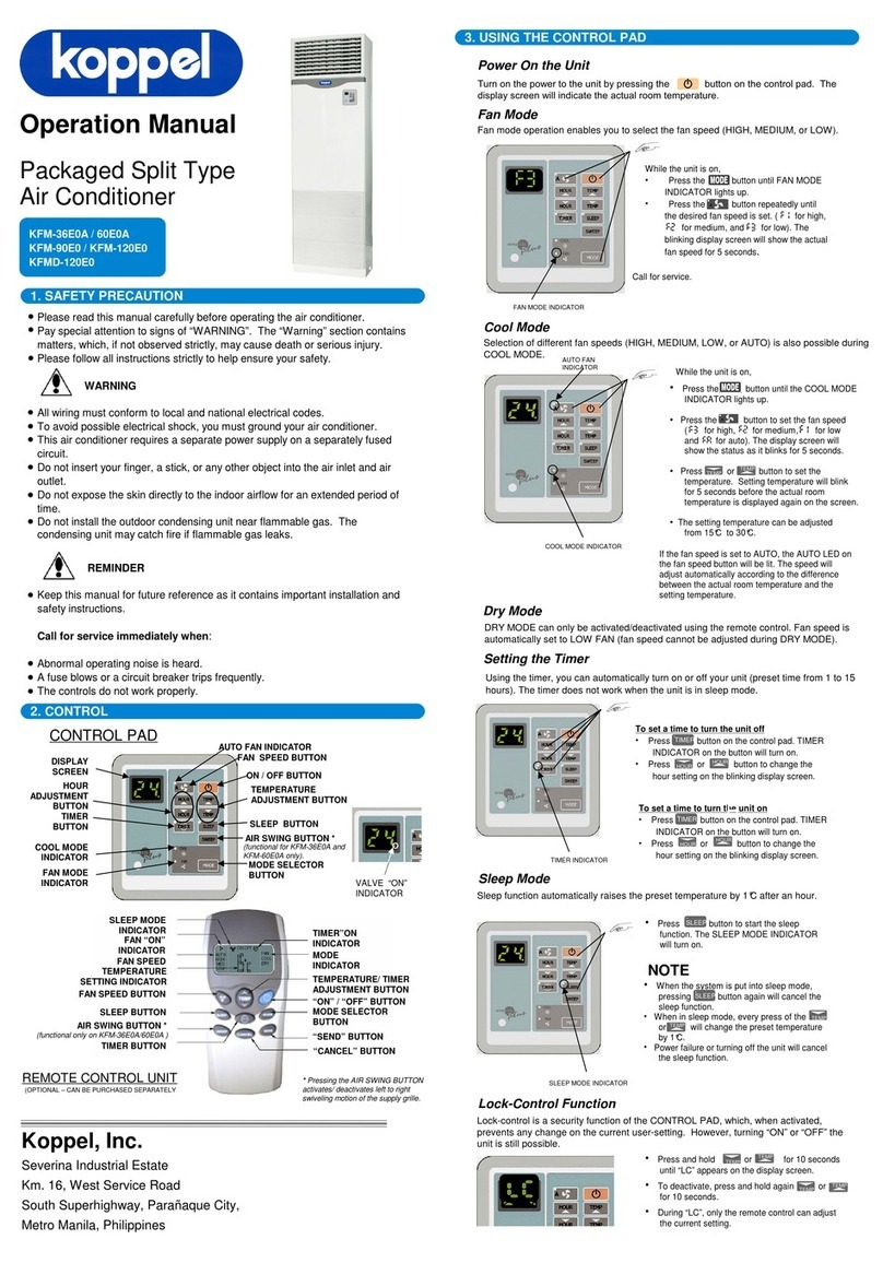
koppel KFM-36E0A User manual

koppel
koppel KV24 ODU-ARF21C User manual
koppel
koppel ERA series User manual