Korg FC6 User manual

FC6
FOOT CONTROLLER
OWNER’S MANUAL

Congratulations and thank you for purchasing the KORG FC6 Foot Controller. To get the most out of this ad-
vanced instrument (?) for the longest possible time, we recommend that you read the manual thoroughly and
carefully.
* Refer also to owner's manuals of the KORG products (such as the A3, etc.) being used with and controlled by
the FC-6 with the special remote cable (RCC - 050, RCC - 100).
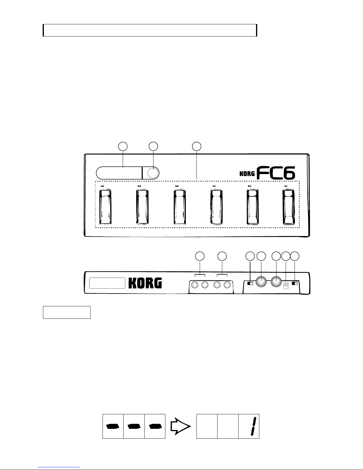
Main Features
In addition to being able to make program changes on connected MIDI effect devices and keyboards, it lets you
easily control volume, pitch bend and other functions with your feet by connected volume pedals and foot
switches
.
It can also control various functions specific to connected instruments which have remote terminals especially
designed for use with the FC-6 (such as the A3 Performance Signal Processor) and it's special remote cable.
Precautions
• ENVIRONMENT
• POWER SUPPLY
• MIDI CABLE
• REMOTE CABLE
• INTERFERENCE WITH OTHER APPLIANCES
• HANDLE GENTLY
• CLEANING
• WARRANTY PROCEDURE
• OWNERS MANUAL
Avoid using this unit in environments where it will be exposed to the following conditions:
Direct sunlight
High temperature or humidity
Dust or sand
Excessive vibration
Use this unit only with the rated AC voltage. If you intend to use this unit in areas where the voltage is different
from it's rated AC voltage, consult your KORG dealer about a suitable voltage transformer unit.
Use only standard MIDI cables less than 15 meters in length.
Use the special KORG remote cable. (RCC - 050, RCC - 100)
This unit uses microprocessor circuits that may cause interference with nearby radio or TV receivers. If prob-
lems occur use at greater distance from the radio or TV.
Although this unit is designed and constructed to KORG's high standards, the use of excessive force may cause
damage to it's switches.
Use only a soft dry cloth to clean the exterior of this unit. Never use (?) cleaners or solvents, polish or cleaning
compounds.
The product warranty ensures that all repairs conducted within one year from the day of purchase are free of
charge, but if the necessary steps were not taken in filling out the warranty card at the time of purchase, por-
tions or all of the warranty may be invalid. Make certain to fill out the warranty card completely at the store
where the instrument was purchased and keep the card in a safe place.
The FC-6 is a sophisticated digital controller with many functions. Therefore, we suggest that you keep this
manual handy at all times, for reference.
!
!
!
!
NOTE: Do not operate the FC-6 and connected external instruments with the remote cable and
MIDI cable both connected at the same time.
-1-

123
FOOT CONTROLLER
888
A B C D E F
45678910
-2-
Names and Functions of Controls and Terminals
(1) Insert batteries or connect the AC adapter (KA 201). When both are set, power is supplied from the AC
adapter.
(2) Connect the MIDI OUT terminal of the FC6 with the MIDI IN terminal of the MIDI device to be controlled
by MIDI cable.
connect the MIDI cable to the remote terminal. it may damage the terminal and cause later
problems.
(3) Turn on the power. Make certain that you turn on the connected instrument AFTER turning on the FC6. The
LED display shown below will appear:
NOTE: Do NOT
(1) Indicates the program number, etc.
(2) Sets MIDI channel.
(3) Selects program number, etc.
(4) For connection to a footswitch such as the KORG PS-1..
(5)
LED display
UTILITY switch
Foot switches A-F
SW ½ terminal
PEDAL ½ terminal For connection to the OUT ½ terminals of the KORG volume pedal KVP-001.
(6) For changing the operation modes of the FC6.
(7) For connection by MIDI cable to the MIDI IN terminal of other MIDI
instruments and devices.
(8) For connection by special remote cable to the remote terminal
of instruments which are compatible with the FC6 (such as KORG A3).
(9) For connection to the AC adaptor.
(10)
MODE ½ switch
MIDI OUT terminal
REMOTE terminal
DC 9V terminal
Power switch
Setting Up:

-3-
OPERATING INSTRUCTIONS
[1] Setting the Mode
The FC6 controls MIDI data in two ways selectable by Mode 1 or Mode 2. The mode switch is located on the
rear panel of the FC6. Select the mode you find most convenient or appropriate for your own purpose.
MODE/SW ABCDEF
MODE 1
MODE 2
The first
number in
the bank
The second
number in
the bank
The third
number in
the bank
The fourth
number in
the bank
The fifth
number in
the bank
Band advance
Preset
number
minus 10
Preset
number
plus 10
Preset
number
minus 1
Preset
number
plus 1
Sostenuto
ON/OFF
Soft pedal
ON/OFF
MODE 1: Making Program Changes by Switching Between Banks
* The following program change messages are output by the operation of footswitches A-F and the values are
indicated in the LEDs.
MODE/SW SW 1 SW 2 PEDAL 1 PEDAL 2
MODE 1
MODE 2
Portamento
ON/OFF
Damper
ON/OFF
Main volume
Pitch bend
(positive
direction)
NO.1 NO.2 NO.3 NO.4 NO.5
NO.6 NO.7 NO.8 NO.9 NO.10
NO.11 NO.12 NO.13 NO.14 NO.15
NO.126 NO.127 NO.128 - -
ABCDEF
Switch
For number selection For bank selection
Each press of the [F] switch advances the bank
number by 1.
Each press of the [E] switch reverses the bank
number by 1.
* BANK: A group of 5 programs, such as
program numbers 1-5, or 6-11, is called a
BANK.
MODE 2: Making Program Changes by Program Up/Down Control
* The program numbers are changed by the A-F switches of the FC6 according to the assignment shown in the
chart above, at the beginning of this section.
[2] Connection of External Switches, External Foot Pedal
The following functions can be controlled by SW ½ (when connected to footswitches such as the KORG PS-1,
PS-2, etc.), and PEDAL ½ (when connected to the KORG KVP-001 volume pedal).
(Operation is the same for both Mode 1 and Mode 2.)

-4-
Specifications
[3] Setting the MIDI Channel
[4] Installing Batteries
The MIDI channel of the FC6 is automatically set to channel 1 when the power is turned on.
(1) “C1” (Channel 1) is indicated in the LED display when the UTILITY switch is pressed.
(2) Change channels by pressing the foot switches A-F. The number (and the operation of the current mode) is
the same as when selecting program numbers.
(3) Press the UTILITY switch again to return to normal operation.
Six C-sized batteries are provided with this instrument. Install the batteries according to the following
instructions.
(1) Turn off the power.
(2) Take off the battery cover at the bottom of the instrument. Remove the screw holding the battery cover in
place with a screwdriver or a coin.
(3) Take out the battery holder. Be careful not to damage the cord of the battery snap.
(4) Insert the six batteries, checking that the positive and negative terminals match the indications on the
battery holder.
(5) Securely connect the battery snap to the terminal of battery holder.
(6) Replace the battery holder and battery cover.
* When battery power is low, the internal indicator flashes. Replace the batteries when it flashes.
* Connect the battery snap to the terminal of the battery holder even when using the AC adaptor. The terminal
of the battery holder might touch the internal plate or other metal parts and may interfere with normal operation.
* Do not connect any other object, except the battery holder of this instrument, to the battery snap.
Display:
Connecting terminals:
Power:
Battery life:
Dimensions
Weight:
Included accessories:
Optional accessories:
Numeric indicator x3; A, B, C, D, E, F (2 colors for each), UTILITY
MIDI OUT, REMOTE, DC9VIN, SW1/2, PEDAL1/2
6x1.5 V C-sized batteries, or AC adaptor (Power supply is not necessary when the remote cable is
connected.)
Approximately 10 hours (continuous use)
(W x D x H): 440mm x 160mm x 42mm (17-5/16” x 6-5/16” x 1-11/16”)
1.4kg (3 lbs. 1 oz.) (including batteries)
6x1.5 V C-sized batteries, remote cable RCC-050 (5m)
AC adaptor KAC-301, remote cable RCC-100 (10m)
Specifications are subject to change without notice.

KORG INC.
15-12 Shimotakaido 1-chrome, Suginami-ku, Tokyo, Japan
1990 © KORG INC.
0302 ETH Printed in Japan
Table of contents
Other Korg Accessories manuals