Korg Nu:Tekt TR-S User manual


- 2 -
Table of Contents
Precautions............................................................... 2
Main features............................................................ 4
Specifications........................................................... 4
Parts List.................................................................. 5
Checking the parts............................................................................. 5
Cautions Before Assembly...................................... 6
Assembly .................................................................. 6
Operation Check..................................................................................7
Troubleshooting ..................................................................................7
Part Names and Functions ..................................... 8
Quick settings .......................................................... 8
Recommended Settings.................................................................... 9
List of mounted parts.............................................. 9
Circuit Diagram .......................................................21
Mounting Diagram..................................................22
Precautions
Location
Using the unit in the following locations can result in a malfunction.
• In direct sunlight
• Locations of extreme temperature or humidity
• Excessively dusty or dirty locations
• Locations of excessive vibration
• Close to magnetic fields
Power supply
Please connect the designated AC adapter to an AC outlet of the correct
voltage. Do not connect it to an AC outlet of voltage other than that for
which your unit is intended.
Handling
To avoid breakage, do not apply excessive force to the switches or
controls.
Care
If the exterior becomes dirty, wipe it with a clean, dry cloth. Do not use
liquid cleaners such as benzene or thinner, or cleaning compounds or
flammable polishes.
Keep this manual
After reading this manual, please keep it for later reference.
Keeping foreign matter out of your equipment
Never set any container with liquid in it near this equipment. If liquid gets
into the equipment, it could cause a breakdown, fire, or electrical shock.
Be careful not to let metal objects get into the equipment. If something
does slip into the equipment, unplug the AC adapter from the wall outlet.
Then contact your nearest Korg dealer or the store where the equipment
was purchased.
- 3 -
DECLARATION OF CONFORMITY (for USA)
Responsible Party : KORG USA INC.
Address : 316 SOUTH SERVICE ROAD, MELVILLE
Telephone : 1-631-390-6500
Equipment Type : EFFECT PEDAL KIT
Model : TR-S
This device complies with Part 15 of FCC Rules. Operation is subject to the
following two conditions: (1) This device may not cause harmful interference,and
(2) this device must accept any interference received, including interference that
may cause undesired operation.
IMPORTANT NOTICE TO CONSUMERS
This product has been manufactured according to strict specifications and
voltage requirements that are applicable in the country in which it is intended
that this product should be used. If you have purchased this product via the
internet, through mail order, and/or via a telephone sale, you must verify that this
product is intended to be used in the country in which you reside.
WARNING: Use of this product in any country other than that for which it is
intended could be dangerous and could invalidate the manufacturer’s or
distributor’s warranty. Please also retain your receipt as proof of purchase
otherwise your product may be disqualified from the manufacturer’s or
distributor’s warranty. Company names, product names, and names of formats
etc. are the trademarks or registered trademarks of their respective owners.
* All product names and company names are the trademarks or
registered trademarks of their respective owners.
THE FCC REGULATION WARNING (for USA)
NOTE: This equipment has been tested and found to comply with the limits for a
Class B digital device, pursuant to Part 15 of the FCC Rules. These limits are
designed to provide reasonable protection against harmful interference in a
residential installation. This equipment generates, uses, and can radiate radio
frequency energy and, if not installed and used in accordance with the
instructions, may cause harmful interference to radio communications. However,
there is no guarantee that interference will not occur in a particular installation.
If this equipment does cause harmful interference to radio or television
reception, which can be determined by turning the equipment off and on, the
user is encouraged to try to correct the interference by one or more of the
following measures:
• Reorient or relocate the receiving antenna.
• Increase the separation between the equipment and receiver.
• Connect the equipment into an outlet on a circuit different from that
to which the receiver is connected.
• Consult the dealer or an experienced radio/TV technician for help.
If items such as cables are included with this equipment, you must use those
included items.
Unauthorized changes or modification to this system can void the user’s
authority to operate this equipment.
Notice regarding disposal (EU only)
If the symbol is shown on the product, manual, battery, or package, you
must dispose of it in the correct manner to avoid harm to human health
or damage to the environment. Contact your local administrative body
for details on the correct disposal method. If the battery contains heavy
metals in excess of the regulated amount, a chemical symbol is
displayed below the symbol on the battery or battery package.

- 4 -
Thank you for purchasing the Nu:Tekt POWER TUBE REACTOR Effect
Pedal kit.
To help you get the most out of your new instrument, please read this
manual carefully.
Main features
• The PowerTube Reactor is an effects kit with a built-in Nutube.
• With this kit, you can use the Nutube to recreate power tube sounds such
as that of a guitar amp, to enjoy an authentic vacuum-tube amp sound.
• The “sag” compression effect that occurs in a power tube is repro-
duced on this kit by using a Nutube vacuum tube, and thus a POWER
SAG knob is featured on this unit to create three-dimensional sounds.
• Add the rich harmonics of the Nutube for an authentic vacuum-tube
amp sound.
• This kit is easy to assemble. All you need to do is attach the bottom
plate, the knobs and the rubber feet.
• The four knobs are easy to operate, and you can turn the internal
semi-fixed volume screws to create the settings you like to match the
sound of your guitar.
• This document includes a detailed circuit diagram, mounting diagram
and list of parts, so you can fully customize this unit to meet your needs.
• A tool and pick set to adjust the semi-fixed volume screws and the
bottom plate screws is included with this kit. You can also use the
included tools when you want to remove and modify the circuit board.
• Affix the included stickers where you like to make this unit look just the
way you want.
• This sticker sheet includes hard-to-find stickers like the Keio Electronic
Laboratories logo, an image of KORG’s legendary engineer Fumio
Mieda and more.
About Nutube
Nutube is a new vacuum tube developed by KORG INC. and Noritake Itron
Corporation and that utilizes technology from vacuum fluorescent
displays.
As with conventional vacuum tubes, the Nutube is constructed with an
anode, grid and filament, and operates as a complete triode tube.
Furthermore, it generates the response and same rich harmonic
characteristics of conventional vacuum tubes.
If a strong impact is applied to this unit, high-frequency noise may
be output. This is due to the structure of the Nutube; it is not a
malfunction.
Specifications
• Vacuum tube: Nutube 6P1
• Connectors and jacks: INPUT jack (monaural phone jack), OUTPUT
jack (monaural phone jack), DC 9V jack ( )
• Power: 9V alkaline battery (6LF22/6LR61) (sold separately), or DC 9V
AC adapter (sold separately)
• Battery life: Approx. 5 hr. (Using an alkaline battery)
• Current consumption: 85 mA
• Dimensions (W x D x H):122 x 96 x 50 mm / 4.80” x 3.78” x 1.97”
• Weight: 324 g / 11.43 oz. (without batteries)
• Included items: Owner’s Manual, Sticker sheet, Tool and Pick set
• Accessories (sold separately):AC adapter (DC 9V )
* Specifications and appearance are subject to change without notice for
improvement.

- 5 -
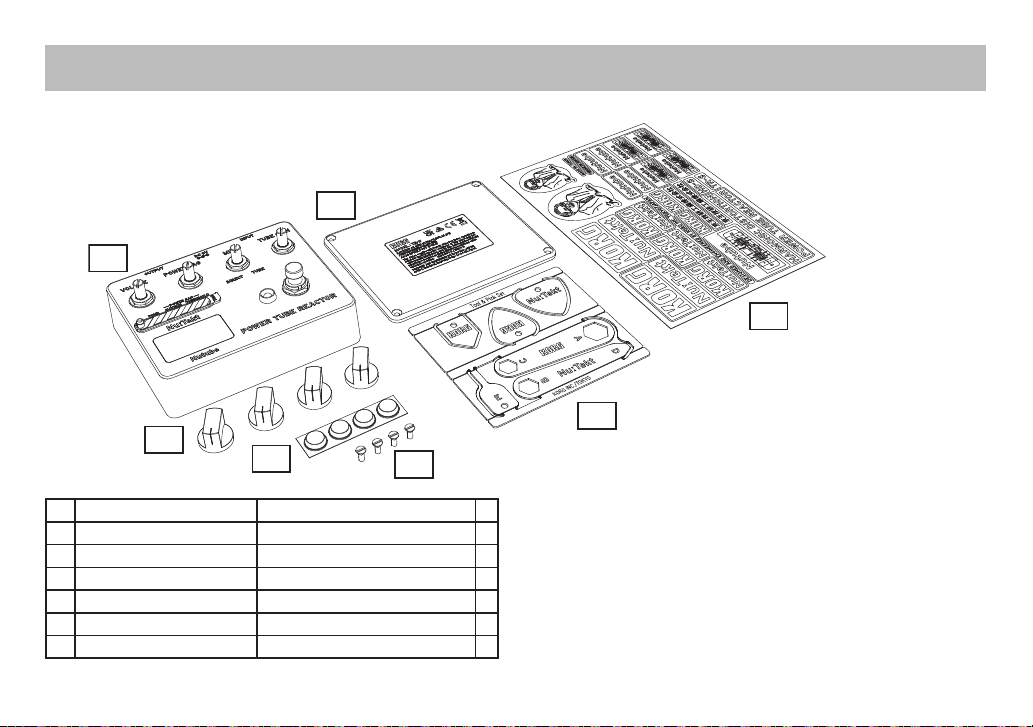
1
2
34
5
6
7
1 Upper case Aluminum 1
2 Lower case Aluminum 1
3 Volume knobs 4
4 Rubber feet Polyurethane 12.7 x 3.6 4
5 Case screws Flat head screw, M3 4
6 Tool and Pick set 1
7 Sticker sheet 1
Parts List
Checking the parts
Before assembly, make sure that all parts are on hand.
Contact us at nutekt.org if any parts are missing or damaged.
- 6 -
Cautions Before Assembly
Be careful of injury when handling parts
Use caution not to injure yourself due to the protruding parts when
handling the circuit board. Use cotton work gloves to protect your hands
when working. Also, be sure to wash your hands thoroughly after working.
Tighten screws at a perpendicular angle
Tightening screws that are inserted diagonally may damage the threads,
making it impossible to tighten them again. Be sure to tighten screws so
that they are inserted perpendicular to the surface.
Use caution, as applying too much torque and tightening the screws too
tightly may damage the parts.
Do not injure yourself or scratch the surface with the
tools.
When using tools to tighten screws, make sure not to injure yourself, such
as by getting your fingers pinched. Work carefully to avoid scratching the
case or circuit board with the tools.
Provide a sufficiently large work space to complete the assembly
procedure, and prepare work mats so parts will not be scratched.
Avoid losing the screws
Handle the screws with caution, to avoid losing them. Do not use other
screws aside from the ones included with this kit, and do not use the
screws included with this kit for any other purpose.
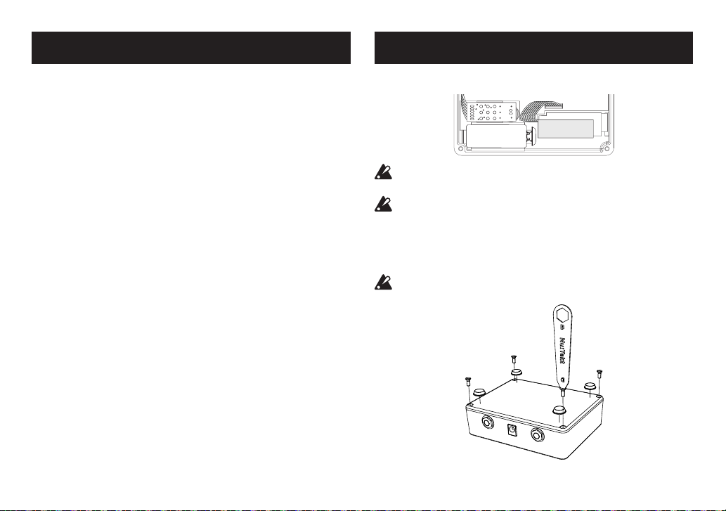
Assembly
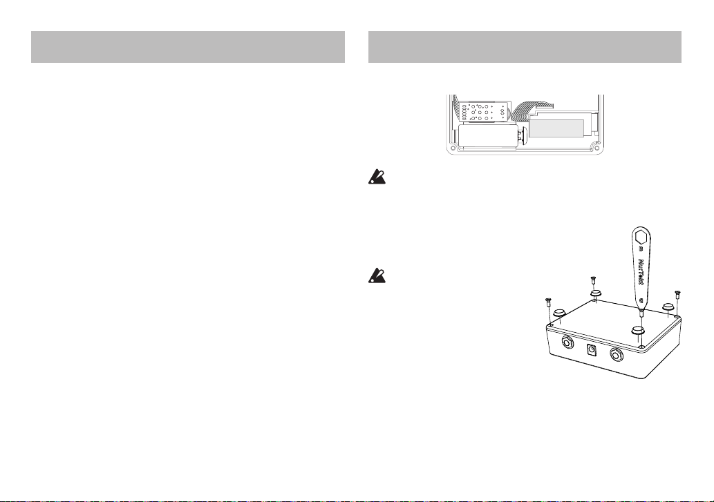
1. Connect the battery and fit it into the battery space.
Batteries are not included. You will need to purchase a commercially
available 9V alkaline battery (6LF22/6LR61).
Store the battery connector in the battery cushion if you won’t be
using the batteries.
2. Close the lower case [2], and secure it with the screws.
Close the lower case and secure it with the case screws [5] in four
places. Use tool [D] for this.
Take care not to pinch the harness or other parts when closing the
case.

- 7 -
3. Attach the rubber feet [4] onto the lower case.
Attach the rubber feet [4] onto the lower case as shown in the
diagram.
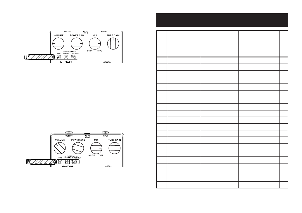
4. Attach the volume knobs [3].
Mount the volume knobs onto their spindles.
Tip: The diagram below shows an easy way to position the volume knob
when installing.
Turn the shaft all the way
counterclockwise
Line up the indicator with
the groove on the shaft
Operation Check
When you have successfully finished assembling the unit, test its
operation while reading “Part Names and Functions” on page 8 .
If you have found any problems with assembly or operation, use the
troubleshooting steps below.
Troubleshooting
There aren’t enough parts.
• If you have lost some parts, contact us at nutekt.org.
• Also, contact us at nutekt.org if any parts were missing or damaged
before you started to assemble the unit.
I can’t assemble the unit, because I broke a part.
• Please contact us at nutekt.org.
The unit makes an abnormal sound when I tilted it or
shook it after assembly.
• A loose screw or other part might be left inside the unit. Open the
lower case and check the inside.
The volume controls or jacks are loose.
• Make sure that the nuts are fastened tightly. Remove the knobs from
the volume controls and retighten the nuts.
• For the footswitch nut , use tool [A].
• For the rear jack nuts, use tool [B].
• For the volume nuts, use tool [C].
- 8 -
Quick settings
1. Start out by making the following settings.
VOLUME knob: center TONE: center
POWER SAG knob: MIN (counterclockwise) SUSTAIN: MIN
MIX knob: TUBE THRESHOLD: MIN
GAIN knob: in the 9 o’clock position
Adjust the VOLUME knob so that the level of the effected sound is
about the same as the bypassed sound (when the effect is off).
2. While playing the guitar, turn the POWER SAG knob to increase the
sag until the Nutube goes dark at the moment that you play.
If the Nutube stays lit even at the maximum setting, turn the
THRESHOLD to adjust the level.
3. Check how the compression sounds when the sag is increased.
For single-coil: the effect increases as you turn the THRESHOLD
clockwise.
For humbucking coils: turn the THRESHOLD counterclockwise to
adjust.
4. If the compression is too strong, adjust by turning the knob to the
DIRECT side to mix the direct sound.
When you mix in the direct sound with a large amount of SUSTAIN,
you can get a sound with an attack but also a long sustain.
5. Use TONE to adjust the attack feel.
We recommend that you set this to a position slightly left of center
(around the 11 o’clock position).
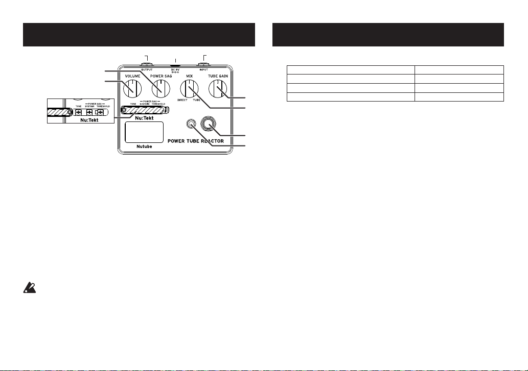
Part Names and Functions
2
OUTPUT INPUTDC9V
1
7
8
4
3
5
6
1. VOLUME knob: Adjusts the volume.
2. POWER SAG knob: Adjusts the simulated “sag,” meaning the
compression sound created by power tubes.
3. MIX knob:
Adjusts the mix volumes of the direct sound and the Nutube sound.
4. TUBE GAIN knob: Adjusts the vacuum tube input level.
5. EFFECT ON/OFF switch: Switches the effector on/off.
6. EFFECT ON/OFF LED: The indicator lights when the effector is on.
7. Adjustable half-fixed volume screws: Use tool [E] to adjust these.
TONE: Adjusts the attack feel.
SUSTAIN: Adjusts the sag sustain time.
THRESHOLD:
Adjusts the level at which the sag effect begins to be applied.
8. Window: Use this to check how the Nutube is lighting up.
To adjust the adjustable half-fixed volume screws (TONE, SUSTAIN,
THRESHOLD), use the special adjustment screwdriver that’s
included in the tool and pick set.
When using a metal screwdriver or similar tool, the Nutube lighting
may change or blink. if the metallic part of the screwdriver touches
the frame of the case while you’re making adjustments.
- 9 -
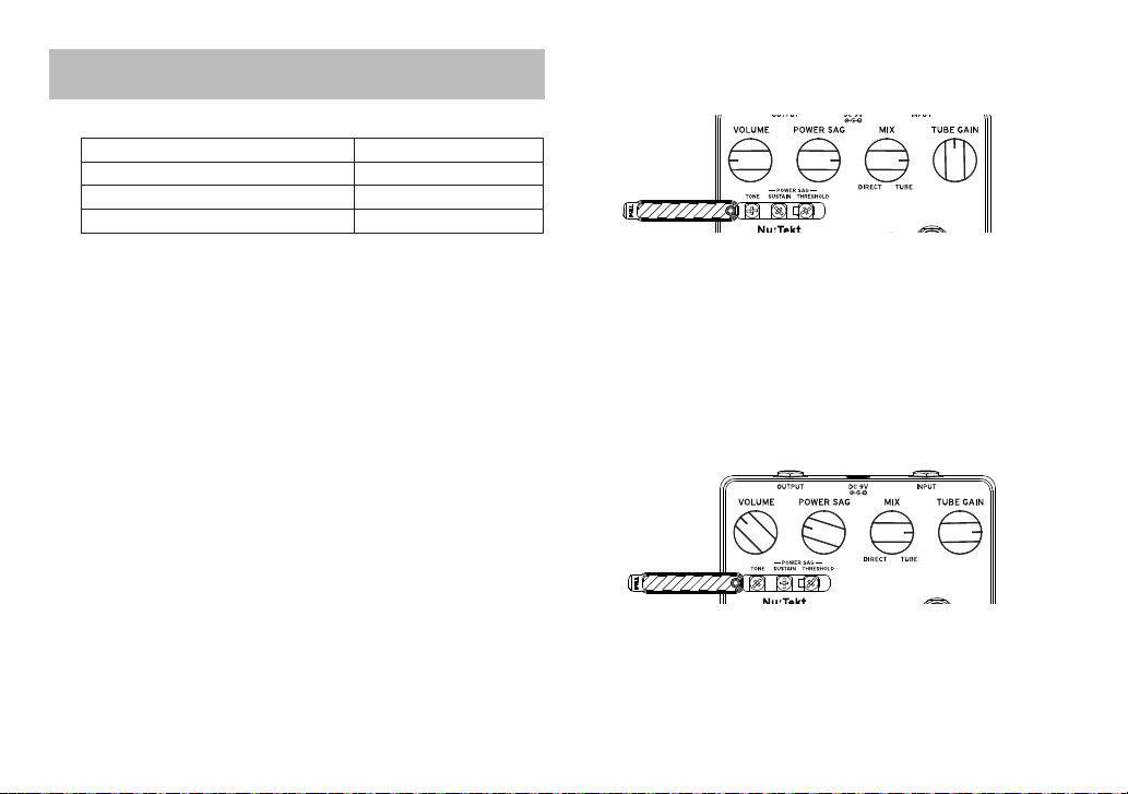
Recommended Settings
General Tube Sound for Single Coil
This is a tube sound that works well with single-coil pickups.
Use this in conjunction with overdrive and connect as follows.
Guitar →overdrive →this unit →guitar amp
In this case, adjust the overdrive output level so that the Nutube on this
unit goes dark at the moment that you play. This gives you a vacuum tube
sound even when you’re playing with a transistor-type guitar amp or
when playing through a line output.
The adjustable half-fixed volume settings are shown below.
TONE: 12 o’clock; SUSTAIN: 8 o’clock; THRESHOLD: 11 o’clock
Jazz Backing for Humbucher
This sound works well with jazz backing riffs played on a humbucking
pickup. Try playing some of the great songs of the past with this setting.
The adjustable half-fixed volume settings are shown below.
TONE: 10 o’clock; SUSTAIN: 9 o’clock; THRESHOLD: 10 o’clock.
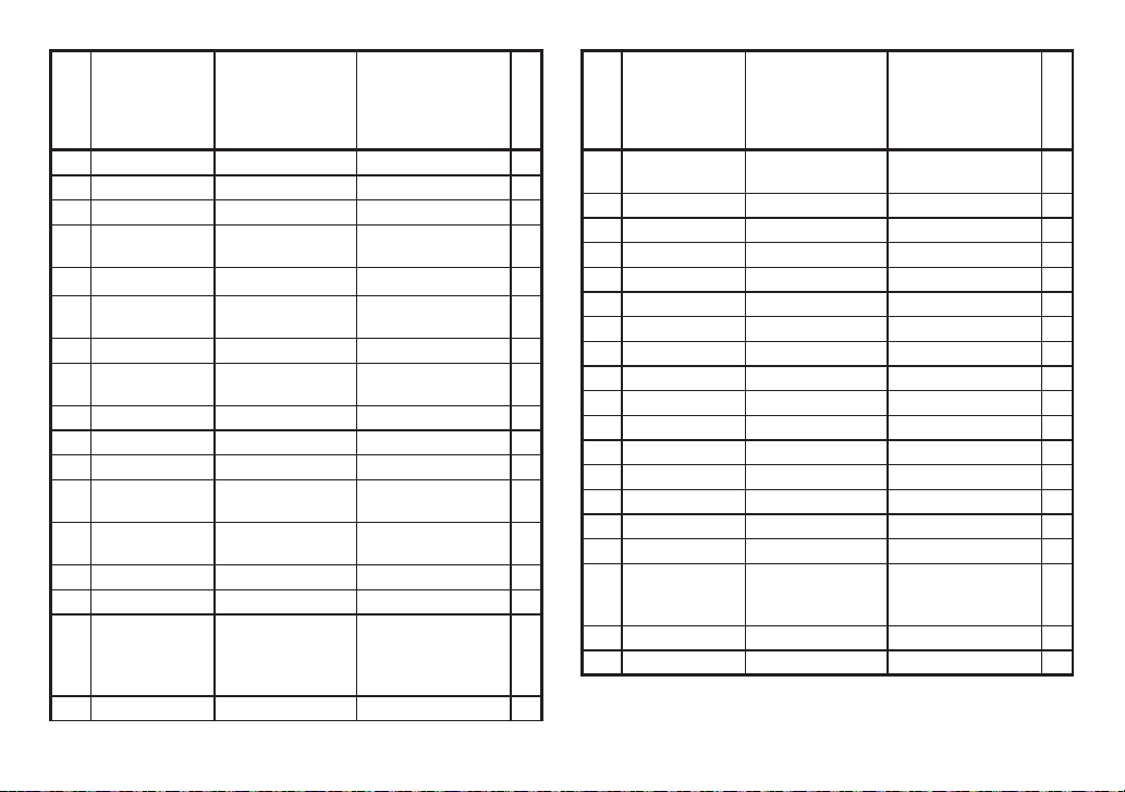
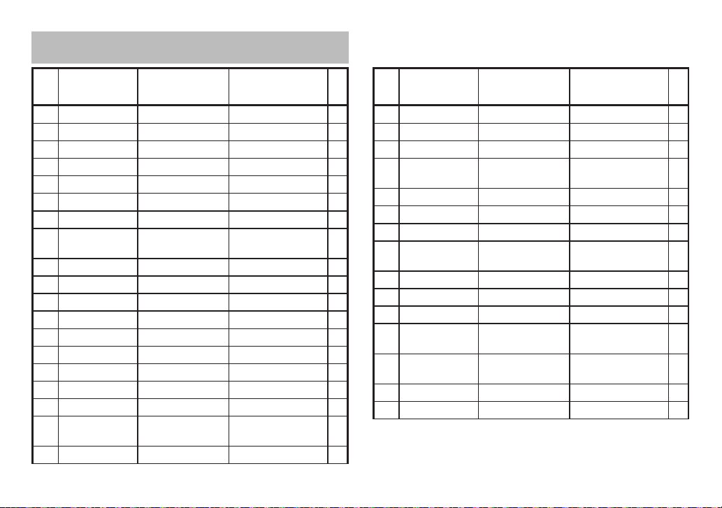
List of mounted parts
Part number
Circuit number
Part name
Rating
Quantity
1 IC2 Regulator IC R1154H036B-T1 1
2 IC6 DC/DC Converter XC9143B10DER-G 1
3 IC1, IC3-4 Operational amplifier SO8412P-TH-WS 3
4 Q3-4, Q6 Transistor 2SC2712-BL 3
5 Q8 Transistor 2SA1162-GR 1
6 F1-2, F5 J-FET 2SK209GR 3
7 D3-4 Switching diode 1SS355 2
8 D2 Schottky barrier diode RB160L-40TE25 1
9 ZD1 Zener diode GDZJ4.7C 1
10 L3 Inductor SMTDR32-2R2M 1
11 EMI1-6 Inductor BLM18BD102SN1D 6
12 C46 Ceramic capacitor 10pF 1
13 C16, C24, C38 Ceramic capacitor 100pF 3
14 C11, C32 Ceramic capacitor 1000pF 2
15 C23 Ceramic capacitor 2200pF 1
16 C9, C31, C33-34 Ceramic capacitor 0.01μF 4
17 C25 Ceramic capacitor 0.033μF 1
18 C8, C12-14, C18,
C28-30, C37, C41 Ceramic capacitor 0.1μF 10
19 C6, C35 Ceramic capacitor 1μF 2
- 10 -
Part number
Circuit number
Part name
Rating
Quantity
20 C39 Ceramic capacitor 4.7μF 1
21 C40 Ceramic capacitor 10μF 1
22 C3 Electrolytic capacitor 0.1μF25V over 1
23 C1, C5, C17,
C21-22 Electrolytic capacitor 1μF25V over 5
24 C20, C36 Electrolytic capacitor 10μF16V over 2
25 C2, C15 Electrolytic
capacitor(NP) 10μF16V over 2
26 C10, C26 Electrolytic capacitor 47μF16V over 2
27 C4, C7, C19, C42,
C44 Electrolytic capacitor 100μF25V over 5
28 R8, R10, R28 Resistor 0Ω 3
29 R35 Resistor 22Ω 1
30 R17, R65 Resistor 100Ω 2
31 R31, R34, R37,
R52, R54 Resistor 330Ω 5
32 R2, R9, R11, R16,
R18, R30, R59 Resistor 1kΩ 7
33 R27 Resistor 2.2kΩ 1
34 R24 Resistor 8.2kΩ 1
35
R13-15, R19, R21,
R26, R33, R38,
R42, R45-47, R49,
R56, R170
Resistor 10kΩ 15
36 R32, R84 Resistor 15kΩ 2
Part number
Circuit number
Part name
Rating
Quantity
37 R1, R4-5, R20,
R22, R41, R70 Resistor 22kΩ 7
38 R12, R25, R39-40 Resistor 33kΩ 4
39 R3 Resistor 47kΩ 1
40 R23, R29, R85 Resistor 100kΩ 3
41 R57-58 Resistor 220kΩ 2
42 R71 Resistor 330kΩ 1
43 R6-7, R51 Resistor 1MΩ 3
44 CN1 Board-in harness 6 wire 1
45 CN2 Connectors B6B-PH-K-S 1
46 CN3-4 Connectors B8B-PH-K-S 2
47 DC1 DC jack LD-0202AH-2.0-03A 1
48 PH1-2 Phone jack LJB0664-6 2
49 V1 Nutube (Vacuum tube) Nutube 6P1 1
50 VR5 Volume control 1K B 1
51 VR6 Volume control 20K B 1
52 VR1, VR3 Volume control 100K B 2
53
VR2, VR4(SUS-
TAIN), VR9,
VR11(ATTACK)
Trimmer Potentiometer
10K B 4
54 VR7
Trimmer Potentiometer
50K B 1
55 BATT1 Battery snap -- 1
Note: An electrolytic capacitor with a higher rated voltage than the
voltage specified may have been used.

- 11 -
- 12 -
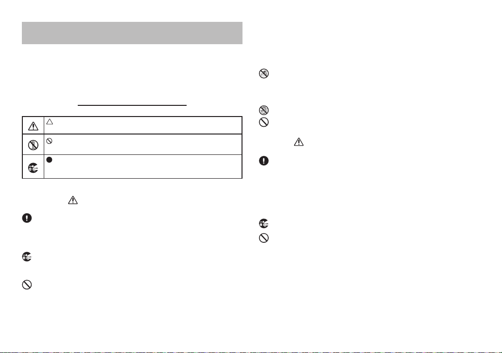
ご使用になる前に必ずお読みください
火災・感電・人身障害の危険を防止するには
図記号の例
記号は、注意(危険、警告を含む)を示しています。記号の中には、具体的な注意
内容が描かれています。左の図は「一般的な注意、警告、危険」を表しています。
記号は、禁止(してはいけないこと)を示しています。記号の中には、具体的な注
意 内 容 が 描 か れ る こ と が あ り ま す 。 左 の 図 は「 分 解 禁 止 」を 表 し て い ま す 。
記号は、強制(必ず行うこと)を示しています。記号の中には、具体的な注意内容
が描かれることがあります。 左の図は「電源プラグをコンセントから抜くこと」を表して
います。
以下の指示を守ってください
警 告
この注意事項を無視した取り扱いをすると、死亡
や重傷を負う可能性があります。
・ ACアダプターのプラグは、必ずAC100Vの電源コンセントに差し込む。
・ A Cアダプ ター のプ ラグ にほこりが 付 着してい る 場 合は 、ほ こりを 拭き 取る 。
・
本製品はコンセントの近くに設置し、ACアダプターのプラグへ容易に手が届くようにする。
・ 次のような場合には、直ちに電源を切ってACアダプターのプラグをコンセントから抜く。
・ 修理、部品の交換などで、取扱説明書に書かれていること以外は絶対にしない。
・ ACアダプターのコードを無理に曲げたり、発熱する機器に近づけない。また、ACアダプター
のコードの上に重いものをのせない。
・ 大音量や不快な程度の音量で長時間使用しない。
・ 本 製 品 に 異 物( 燃 え や す い も の 、硬 貨 、針 金 な ど )を 入 れ な い 。
・ 温度が極端に高い場所(直射日光の当たる場所、暖房機器の近く、発熱する機器の上など)
で使 用や 保管 をしない 。
・ 振動の多い場所で使用や保管をしない。
・ ホコリの多い場所で使用や保管をしない。
・ 風呂場、シャワー室で使用や保管をしない。
・ 雨天時の野外のように、湿気の多い場所や水滴のかかる場所で、使用や保管をしない。
・ 本製品の上に、花瓶のような液体が入ったものを置かない。
・ 本 製 品 に 液 体 を こ ぼ さ な い 。
・ 濡れた手で本製品を使用しない。
・ 電池は乳幼児の手の届くところに置かない。
注 意
この注意事項を無視した取り扱いをすると、傷害を負う可能性、ま
たは物理的損害が発生する可能性があります。
・ 正常な通気が妨げられない所に設置して使用する。
・ ラジオ、テレビ、電子機器などから十分に離して使用する。
・ 外装のお手入れは、乾いた柔らかい布を使って軽く拭く。
・ ACアダプターをコンセントから抜き差しするときは、必ずプラグを持つ。
・ 長時間使用しないときは、電池の液漏れを防ぐために電池を抜く。
・ 長時間使用しないときは 、ACアダプターをコンセントから抜く。
・ 指定のACアダプター以外は使用しない 。
・ 他の電気機器の電源コードと一緒にタコ足配線をしない。
・ 電池を過度の熱源(日光、火など)にさらさない。
・ スイッチやツマミなどに必要以上の力を加えない。
・ 外装のお手入れに、ベンジンやシンナー系の液体、コンパウンド質、強燃性のポリッシャーを
使用しない。
・ 不安定な場所に置かない。
・ 本 製品の 上に 乗ったり、重 いも のをの せ たりしな い 。
- 13 -
- 14 -
1
2
34
5
6
7
1
1
2
1
3
4
4
4
5
4
6
1
7
1
- 15 -
1. 電池を接続し、電池スペースに収めます。
2. 下ケース[2]を閉め、ネジで留めます。
3. 下ケースにゴム脚[4]を貼り付けま
す。

- 16 -
4. ボ リュ ー ム・ノブ [ 3 ] を 取 り 付 け ま す 。
Tip:
軸 を 左 に回しきりま す
指標を軸の溝に合わせます

- 17 -
2
OUTPUT INPUTDC9V
1
7
8
4
3
5
6
1 . V O L U M Eノブ:
2 . P O W E R S A Gノブ:
3.MIXノブ:
4.TUBEGAINノブ:
5.EFFECTON/OFFスイッチ:
6.EFFECTON/OFFLED:
7 . 調 整 半 固 定 ボ リュ ー ム:
8 . ウ インドウ:
- 18 -
1. まずは以下 の設定にします。
2. POWERSAGノブを回してギターを弾きながら、Nutubeの光が
弾 い た 瞬 間 に 消 え る くら い ま で S A G を 大 き くし ま す 。
3. SA Gを大きくしてコンプレッション感を確 認してみましょう。
4. コンプレッションが大きすぎる場合はDIRECT側に回してダイレクト
音をMIXして調整します。
5. T O N E で ア タッ ク 感 を 調 整 し ま す 。
- 19 -
部品
番号 回路記号 品名 規格 数
量
部品
番号 回路記号 品名 規格 数
量

- 20 -
部品
番号 回路記号 品名 規格 数
量
部品
番号 回路記号 品名 規格 数
量
*
Table of contents
Other Korg Music Pedal manuals

Korg
Korg Nuvibe User manual

Korg
Korg KAOSS PAD KP2 User manual

Korg
Korg FK1 User manual

Korg
Korg ToneWorks AX3000G User manual

Korg
Korg Toneworks AX1G User manual

Korg
Korg ToneWorks AX5B Product information sheet

Korg
Korg Nu:Tekt OD-S User manual

Korg
Korg pitchblack POLY User manual

Korg
Korg MIKU STOMP User manual

Korg
Korg Pitchblack Custom User manual


