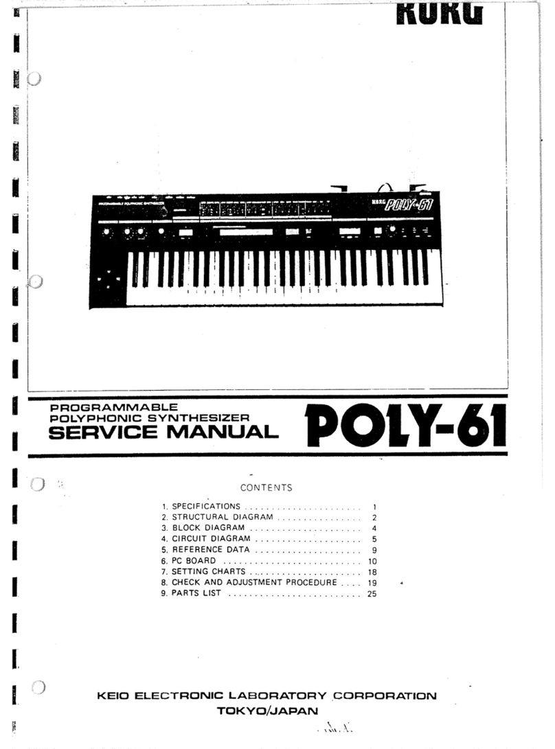
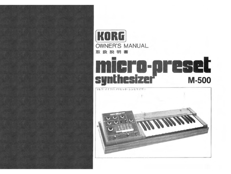
Korg PS-3200 User manual

KORG PROGRAMMABLE APHONIC SYNTHESIZER
Owner's Manual
7° p?^a•*° J7*^y ?•*> >-t? hmIf
ps-3200 m^mmm
Soondl
Revolution]
KORG

PROGRAMMABLE POLYPHONIC SYNTHESIZER
pi ©
KORG PS-3200li, Mini KORG Cft&Stt* st-ft^ •^V-b-fr
4^-0&'tfr£!MilT -Synthesis!" <0 ^£%l%3tf fc .fVfc<?>
fix. ri» s&0-r* *> ,*im# *>-t *-f ik-»&©#»**»
©"T*6tt* 5<^ l-ft£^L, £<$ff L<•• S'V-t-*- A4?-o>'itWQ\ ')
INTRODUCTION
Thank you for choosing the PS-3200 Programmable
Polyphonic Synthesizer. We developed this instrument as an
improved and memory-equipped version of our polyphonic
PS-3100 synthesizer which has attracted much attention from
the world's leading musicians.
As is the case with our other polyphonic synthesizers, you can
play as many keys as you like at the same time. Each key has
its own microelectronic IC synthesizer circuit. The biggest
feature of the PS-3200 is that it has amemory. You can
program it to remember 16 completely different tone colors
that you are free to create as you would on an ordinary
synthesizer. Programming is as simple as pressing abutton. If
you have been using monophonic synthesizers, rest assured
that we have sacrificed nothing in converting to polyphonic
operation. You can even use the PS-3200 just as you would a
monophonic instrument, if you like. But with this polyphonic
capability you can create rich harmonies without the
intermediate step of multitrack tape recording. This makes the
PS-3200 highly suited to live performance applications. The
whole of our PS-Series offers you this kind of excitingly
innovative approach and solidly dependable performance, so
that you can go beyond the limits of conventional synthesizers
and explore the musical universe at will.
WARNING
To reduce the risk of fire or electric shock do not expose
this appliance to rain or moisture.

c
DROOD EW
^
CML®m MM ajov>1
,yuvov-cpv^u 2-12 AD1DR3© AMPLIFIER lABGIJ^IMIPS
Vy-^yO ^>7(ADD-AMP)
y-^jutz^ 2-13 JIMRflETTDGDRD EJTOIBB
i/»C7S/3>(JUNC)
o3 7D<7'^y-(PR0G) 2-H4 OEDQRECT WfflLMME KGD-WffiO
•7-r bcs •tkuzl-^(d-vol)
1-1 HOW TO USE IT OIPKIODB^IE WGDtHlflRJflE EG»«W(EDO
~J-x—y •TKUa—Zj(p-vol)
1-2 PROGRAMME OFDGMfcD. VOLUME IF'WOILJ
37Wi-)[y /K'Jzi-^(F-VOL)
1-3 THE CBMOS-UP BATfEKIE T\ mEQDRDTTOBflDG. EREM®"(EM5)
ut—kd>sd—;kremo-con)
1-4 CHAH!1(ED[R!I(B BATTERIES DEPROGRAM REMOTE CONTROL OD^DIT PS-3060
m* FEMFU G^(OTS> %B(D¥>m<tL 2-16 ©®0» ©©NNECTOR ARD© [POWER SQJJPPILV
60PD^C?5>-£^l!
2-1 SIGNAL GENERATORS (SGI
yj-y\\j yi*u—5>-(sg) OP©LWC-3©M0© GSEVEOARD PS=3©i]©
1$J-J-*—-yO ^-7l\-KPS-3010
2-2 DYNAMO© LOW-PASS FILTERS
5^-f^-S'VC •D-/U •7-f)b5>-(.DLPF)
2-3 ENVELOPE MODIFIERS CEM)
j:y<a-7 •^t'-t^WJ'-CEM)
©[LOME) gfflROfflX] 3*:CD1U3S
3-1 TERMING ABOUT SMUD SYNTHESIS
2-4 E^PALIZER (Ep
fD5-l'+f-(EQ)
2-5 TOTAL SflGRJAL SOT10PIERS IT SM)
I
—
5»b y?J-)b ^tV^T7>-(tsm)
3-2 SflGNAL FL©M
3-3 THE BASIC ELEMENTS OF SOUND SYNTHESIS
OCSEVEMDARD VOLUME BALANCE C8£ES1°\!?°(SAL1
dp—;K— S•tKUzl—Z_> •M'^^Ckbd-v-bal) 3-4 UNDERSTATING THE PATCH
OAlffiliPOTtlDlE GMIQDILATOR EATO
JP^'J^zi-K •:E=;zib-5'-(AM)
•ENSEMBLE CESBJ
3-5 :ERONG EXAMPLES
4. P[^ ©/Me® C" "U" [p i i mPS-3200£
PSS/U-X
•VCA-1/PRESE^
vca-1 /TTUtzwh- •
WOLMIiME EWEA-H/IPRE W
Ua-Zj(pre-vol) 4-1 SPEOPCCATOONS
tt
OV7CA-2/PRESET WOLtUJIME CVCA-2/PRE VOO
vca-2 7Utz\yf- •7|\Uzl-Zj(pre-vol) 4-2 KORG PS-SERGES
Dii-Vpsyu-X
IM©©©LATQ©NJgA[LAN©E/[i!ffl®©(II![LA¥GfflN W©A CME L/WIVCAI
^zlU—~/a> •i\-z>yz. ^Vnv—y^y vca(m-balxm-vca) /MJF0®R] ^ffl-toaI'liN
2-7 SAMPLE &HOLD IS/C33
U>7Jl/ •J>>K •/Tv-JUK(S H) 5-U ©AQJTOfflN MREN SETTGN© CDC2APATER
IVi/9- 7—5COUT
•B ROTlQjJILATOfflN GENERATORS EEflG-13)
"E^zlL^— ~/3> •5/x^L/—S?—-1 (MG-1 )
2-9 MODULATION GENERATOR-2 (MG-2J
=E93.[s—~/3y VT.^-ly—9—2(MG-2)
5-2 E©P EONNEETER EAQDTOEN
60P3^C5'-C-Ol\T:
TR©(L0mESR©©T0N(B
I© GENERAL ENVELOPE GENERATOR CGEG1
=>i*^Jl/ I>^D-7 -~/i*Ly—9-(GEG)
2-11 WELTAGE PROEESSER GWP2
/KJl'T—2/ •T'DtZ^-y—(VP-T-VP-2)
tz^-rX/fSy

yuvov^yo^Li
-f IK-PS 3200IJ .2 J&<0 ftf-?* -i-'ai *u-
Jf- (VCOli)") fZ-fti ^LP7i'^-.x
-ft fc'0>32=»<0';± At: iit'/ff >^frl6M-
:i. PS 3200fr«flK*->K- Kfc t-C Willi -f &*
*r/. t ft >, T^i"*. Fir 2tt. PS 320007* o
-,'/ *Vi7'Sv is-C-fo OWj:: IW )5ff £
This synthesizer employs two signal genera-
tor modules (which include the waveform
generating VCO circuitry) along with many
other signal snapping and control modules
including dynamic low-pass filters, en-
velope modifiers, and a7-band equalizer.
With the total of 32 control knobs found
in these modules you can create virtually
any tone color. Then you can have the
memory remember that setting, no matter
how complex. In this block diagram you
see the signal paths of the audio signal and
the control signals. By studying this dia-
gram and familiarizing yourself with the
pattern of signal flow, you will be able to
work out the most troublcfree method of
creating any particular sound. The shaded
blocks in the diagram are those modules
that the memory will remember the set-
tings of.
•SIGNAL GENERATORS
F,
*l
Fig. 1PS-3200 +PS-3010.
X48
/AMPLITUDE
MODULATOR
X48
ATTACK
CVIN
RELEASE
SWIN
60P
CONNECTOR
-A IMGl '•' iN
T-rrm
'.PRESET
'/VOLUME
f
.JDIRECT
-*J0UT
jrv SVCA 1
CVIN
i
FINAL
OUT
MODULATION
GENERATOR 2/> OUT
!!
!*_r
VOLTAGE
PROCESSOR 1
!
!
HEAOPHONf
OUT
GENERAL
ENVELOP
GENERATOR
VOLTAGE
PROCESSOR 2f
VP2
-A ioUT
OUT
CLOCK OUT
Fig. 2Block Diagram.

•NORMAL SETTING
Ki K.3«P 32O0W /--r >" --t y r-f >^"Ci".
—>Ali
,ftfci**Bfi't:l*, Fig. 3tOiA DC-t yf^
-^JKtSJSiBJjtJIJ^ Fig. 3CO/--?^ --fc 7T
5.
Figure 3shows the "normal seating" for
one unit (channel 1) and the mixer of the
PS-3200.
With this setting, all modulation functions
are turned off to produce asimple organ
tone. If you don't get an organ tone,
you've probably missed one of the knobs
or switches; go over Fig. 3again.
This manual uses the normal setting as a
starting point for all further explanations
of synthesizer functions and operation.
Learn how to return to this setting quickly
and effortlessly whenever you want; it will
make your relationship with the synthe-
sizer alot smoother.
TEMP ADJ
SG-l SG-2
B
SG-l
WAVEFORM SG-2
WAVEFORM DLPF
fc EM
ATTACK EQ
•(Cm) ®®
SCALE SCALE PEAK DECAY
ooo2K fl)
TUNE KBD FBAL SUSTAIN
C\\ 1€t
Pww
SPEED INT EXPAND RELEASE 25o iD
i25 UD
00
TOTAL SIGNAL MODIFIERS
ENSEMBLE
KBD VBAL
FM INT fcM INT MBAL CLOCK FREQ RELEASE
PROGRMMABLE
POLYPHONIC SYNTHESIZER
oooooboo
12 345678
oooooooo
9 10 11 12 13 14 15 16
REMOTE CONTROL
PROG 60P BATT
oO
MP POWER
fl-O
oKBD TRIG
SELECT MOMENTARY PS-3010
Fig. 3Normal Setting.
ooo
AMP
HEAD PHONE
olldllo
\Z3
"O
AMP
<t AC

1. PROGRAMMER CPROG1
^^y-(PROG)
1-1 HOW TO USE IT
KflRG
PROG
O
cs
POLYPHONIC SYNTHESIZER
OOOOOOOO
l 4 Kft /8
nan
OOOOOOOOO
WRilf y1C II J? li 14 li 16
REMOTE CONTROL
sPROG
REMOTE
<.-.>' BAIT _
oO
MP POWfcR
HO
Fig. 5
Fig. 4PROG
I-l61Tflfeifct«L-C«< **•)-'<>
2XT *< •yf-fttfT£LEDiS'-5t8t JT.
•PROGRAM SELECTOR
Each of theso sixtoon buttons is for
adifferent tone color setting. When
you press abutton an LEO indi-
cator lights up.
•+i-^-tii---t-y rX-f -/*
PS 3200<D"*rt'_LTa&4-tt$>aK If)*
<'/^frJf-Ti:- ro^Ati-?^--toy
<y -**+ ^tn-Jftl T. ^o^it
u£ *-1: /*'I -1ft *&u ;otKSTft
fiL J'f
•CANCEL/SET
Whon you press this button it con-
eels one of the memories so that
you can set up the control panel for
anew tone color setting.
•5-f YX4v*
PS 3200 i:Kte?« ft /:*>«•* £/»;<-f /
-4-(§Mi:t¥L fc *i- '**«•<»> *-/^-f ^
•WRITE
When you press this button and one
of the program selector buttons at
the samo time, the tono color sot-
ting that you have created will be
put into the memory.
i<r@* i-^^t7Mi'v+4r« L.ft
t- ?:> u>x4-y +4rOFK( I.) i: LT</**#*••
-Cu. wcc-Cjicn/.-WKiri-: <*o .';
&JAA) Il6ffiOsKJr>4'MW(:JT Lt</-'?<•.,
-ViT"iJ£ttCCW.:CANSEU SET 0D*f?>«D
7i>/7/.-Cu 99-0 \M*>tfttiifi *- K
ft'j&*8 LiL/,-. -Iff. 16JfrC)-7'o ?*9 as: /
--v /i- -t -/ -7- i>'Stf A*V-&*lHfci -rV'"
C'C*.* btf>5* i- >>ti-r.|i?H/-' SBW' iA
VPIfeL tAT <ATS>1' fcl*jY(iWt>S:ltL '*
i-;irrt„ ;*::. '>i A^'ji-.ti-.-cfi^.H''
LtAt<^5i'. vur?a/>< ffli?>ffij(: *-V >
As an example, these instructions will show
you how to put the normal setting into the
programmer's number sixteen memory:
Press the C/S switch (marked (X) in the
diagram) and set controls to the "normal
setting". Turn off the memory protection
switch (by pushing it up) which is located
to the left of the power switch as shown
(g> in the diagram. When this switch is off
it allows you to write in anew program.
Assuming that you have set up the control
panel for the so-called "normal setting",
press the write button (marked (C) in the
diagram) and the number 16 program selec-
tor button at the same time. This will put
the normal setting into the number sixteen
memory. In other words, the program
input process is as simple as pressing these
two buttons. You will notice that as you
press the write and 16 buttons together,
the I.ED above the CVS switch will turn off
and the I.ED above the number 16 button
will turn on. In this condition, try playing
the keyboard and turning some of the
control knobs in the sections of the control
panel that are outlined in orange. Nothing
should change in the reproduced tone-
color if you have followed all of the in-
structions correctly. Now try pulling out
on one of the control knobs and turning it.
In this case, you will be able to change
parts of the reproduced tone color at will.
When you press back in on the knob, the
setting will go back to the "normal setting"
that you have programmed into the num-
ber sixteen memory.

1-2 PROGRAMMING yw7^L>
PS 3200(i. KiK.6i:#Mfc-C*Jj< 3ft TI- 632=
V*4v+k^'a 77 J**^ ?2-0> r9j 4-l.i]
»i:ffLt <L'iX'o
cconjft. Uifiu *-*y -sft-cw.-.-YCi*1*
-v>-t'*3ft. *«+*» i.cortti-* 1r9j w^-ty
-'<> ^^ftiitsn/w'C bu&4 *-r.
KUWW-T. Htt->fcft€S*fl** ri2j ->**
y—-mur, -tp^ ari2j t:£ttf&6hiJ
COJ: »i:,PS-3200tta6«BW>«fc*ie*f
J-HHKfrWoT t.'*-v9-9- (W3 x23
V) -C'f-y »T ^7*3*1, ^-tV -Sft/,-fY&IJ,
a) ^v-yoT-oy-tf rONj cowsria,
rFFj CUI^5|Sa*«UI<tfcilV
All of the settings of the 32 knobs shown
in figure 6can be put into any one of the
memories (1 through 16). To accomplish
this, first press the C/S switch (you have to
have the MP switch off to do this). Then
adjust the control knobs until you get the
tone color that you arc aiming for. (You
can use the setting example as areference.)
Once you have gotten the sound you want,
simply press the write button along with
the program selector butoon that you want
to use to remember that particular tone
color. In figure 6you sec that we have
arbitrarily selected button number one for
this particular tone color setting.
You can put adifferent tone color setting
in memory 2(by going through the same
process), another setting in memory 3, and
so forth. Altogether the memory bank will
store up to sixteen different tone color
settings that you arc free to create and
alter (by pulling out and resetting any of
the control knobs) at will. These settings
will remain in storage, whether you turn
off the power switch or not. This is pos-
sible because there arc batteries (two 3V
batteries) that keep the memory alive. You
must pay attention to the state of these
back-up batteries in order to protect the
memory bank.
Note that the memory protection
switch is merely aprecautionary device
that prevents you from accidentally
erasing amemory (by mistakenly press-
ing the programmer buttons). This MP
button must be in the OFF position
when you write in anew program.
SKUCl *0«E*'*B'PS-3010
Fig. 6
Fig. 7

1-3 THE BACK-UP BATTERIES My^y^M^U-EOlvc
•BATTERY LIFE INDICATOR
LAMP
When this turns on it means that it
is time to toplacc the batteries. But
this must be done with the power
switch on (and the power cord
plugged into an AC socket) in order
to prevent the memory bank from
being erased.
N(T)OttS-C-UrD^7A^>B*iiA9«T
•MEMORY PROTECTION
SWITCH
This is your memory protection
(MP) switch. By leaving it in the
ON position you can protect the
memory bank from accidental
erasure.
Fig. 8Memory protection yFUS£ 2k 2$W
TOLTA'J>_
SELLCIOR
6ATI£K< SUM 3*? 3V
PRQGRAWAABIE
PCWlOWC SYNlHl$)?fR
M0DF1 PS-3200
SlMAl NO.
K£« tliCIRONIC'i'AB.CORP.
TOKYO/ JAPAN
AC 10O/il7/??O/2GQV
SO/bOM* WW
TKEtO GIKtN
Fig. 9 Rear panel.
1-4 CHANGING BATTERIES MftxWi
I
Battery case
vBitt.(t r.ujmft n,x;i ##& lfc ii io#j l*p
tWHIf***.<»*:. fflJLtUCi frftft&ft
BATTERYOD%*#*'* *-K*'*>*•& <£fa lfi
«jfiB«»'j,$ffot»^i'^( ac*3a)«o
JEitecoffira ;S3:5fl(r)«t\»iiza»u"C3Sg&ur
•New batteries will last for about one
year from the date you put them in. We
put batteries in at the factory, but since
you probably do not know how long the
3200 took to get from us to you, you may
wish to put in new batteries. Then you can
replace them in one year's time, whether
the battery life indicator lamp lights up or
not.
•When you do replace the batteries,
please remember to have the synthesizer
plugged into an AC wall socket, and have
the power switch turned on. You should
have the memory protection switch turned
on as well. Make sure that you have the
plus and minus ends of the batteries in the
right directions when you insert them.
Please Note That If the AC Power is Off
When You Take Out the Old Batteries, the
Memory Bank Will be Instantly Erased.
Should This Happen, You Will Have to
Reprogram it.
•BATTERIES
Use two 3-volt
AM-31. batteries (type
PS 32000) /4V -fS *3230>oi *l*Flg.
Wliit-fc fa ±0>a*V -^tti'Wt i-r„
:wj? i:ps 320ot: *«y -sn/jUfCt**.
•» ,VCO. VCF. VCA. KM. ftKMt.S). MG
While you are using any one of the sixteen
memory programs, you can alter any part
of the tone color by simply pulling out and
resetting (in the pulled out position) any of
the 32 knobs (in those scetions that can be
put into the memory). (Of course the other
controls always continue to be adjustable
as usual.)
When you push aknob back in, then it
returns automatically to the setting pro-
grammed into the memory (though the
knob does not actually turn by itself; the
process is purely electronic).
All this means that when you use different
amps from usual, or if the acoustics of the
hall you are playing in are different, you
can perform the necessary adjustments to
compensate for variations in reproduced
tone color.
Other manuals for PS-3200
1
Table of contents
Other Korg Synthesizer manuals