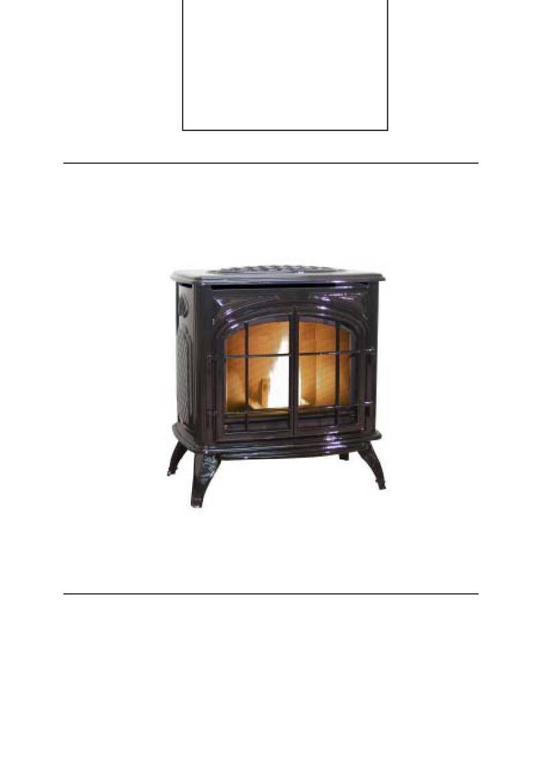
Kozi CDVI User manual

1Rev. July 2010
KOZI CDVI INSTALLATION AND
OPERATION MANUAL
Appliance Type: Direct Vent Gas Fireplace Heater for installation in solid fuel fireplace.
Test Standard: Harmonized, ANSI Z21.88 CSA 2.33-2002, CAN/CGA 2.17
Proper installation, operation and maintenance procedures are critical to all gas fired
appliances. Please read this manual thoroughly and retain for future use.
WARNING: If the information in these instructions is not followed exactly, a fire or
explosion may result causing property damage, personal injury or loss of life.
•Do not store or use gasoline or other flammable vapors and liquids in the vicinity
of this or any other appliance.
•WHAT TO DO IF YOU SMELL GAS
oDo not try to light any appliance.
oDo not touch electrical switches; do not use the phone in your building.
oImmediately call your gas supplier from a neighbor’s phone.
oFollow your gas supplier’s instructions.
oIf you cannot reach your gas supplier, call the fire department.
•Installation and service must be performed by a qualified installer, service agency
or gas supplier.
This appliance may be installed in an aftermarket, permanently located, manufactured
home (USA only) or mobile home, where not prohibited by local codes.
This appliance is only for use with the types of gas indicated on the rating plate. This
appliance is not convertible for use with other gases, unless a certified kit is used.
APR Industries Ltd. 1354 Waverley Street, Winnipeg, Manitoba, Canada, R3T 0P5

2
TABLE OF CONTENTS
INTRODUCTION......................................................................................................................... 3
KOZI CDVI SPECIFICATIONS .............................................................................................. 5
KOZI CDVI GAS CONTROL PARTS LIST........................................................................... 5
UNIT DIMENSIONS.................................................................................................................... 6
REQUIRED INSTALLATION COMPONENTS...................................................................... 7
INSTALLATION REQUIREMENTS........................................................................................ 8
CLEARANCES............................................................................................................................. 9
COMBUSTION AIR INLET AND EXHAUST GAS OUTLET............................................ 10
GAS SUPPLY AND HOOK-UP................................................................................................ 11
GAS SUPPLY AND HOOK-UP................................................................................................ 12
SURROUND ASSEMBLY......................................................................................................... 13
SURROUND INSTALLATION................................................................................................ 14
FINAL ASSEMBLY................................................................................................................... 15
FIREBOX ACCESS.................................................................................................................... 16
CERAMIC BOARD, LOG AND EMBER INSTALLATION................................................ 17
LIGHTING INSTRUCTIONS .................................................................................................. 18
MAINTENANCE........................................................................................................................ 19
GLASS MAINTENANCE AND REPLACEMENT................................................................ 20
BURNER PRIMARY AIR ADJUSTMENT ............................................................................ 21
BLOWER OPERATION ........................................................................................................... 22
BLOWER WIRING DIAGRAM............................................................................................... 24
OPTIONAL EQUIPMENT........................................................................................................ 24
WWW.KOZISTOVES.COMLIMITED LIFETIME WARRANTY..................................... 24
LIMITED LIFETIME WARRANTY....................................................................................... 25
RATING PLATE DIAGRAM................................................................................................... 26
REPLACEMENT PARTS LIST............................................................................................... 27

3
INTRODUCTION
Your KOZI CDVI is a quality gas-burning appliance. With proper installation and
maintenance, it will serve you well with many years of trouble free heating, and the
wonderful ambiance a gas fireplace adds to your home.
Before beginning the installation of your appliance, read these instructions through
completely and consult your local building authority. Install the unit and its’ venting
system only as described in these instructions.
This appliance and its’ approved components are safe when installed according to this
installation manual and are operated as recommended. Unless you use approved
components tested for this appliance, YOU MAY CAUSE A FIRE HAZARD!
The warranty will be voided by APR Industries Ltd. for the following actions:
A) Modification of the appliance or any of the components manufactured by APR
Industries Ltd. unless otherwise permitted by APR Industries Ltd.
B) The use of any component part not approved by APR Industries Ltd. in
combination with this appliance.
C) Installation and/or operation in a manner other than instructed in this manual.
D) The burning of anything other than the type of gas approved for use in this
gas appliance.
APR Industries Ltd. also disclaims any responsibility for the above actions.
This appliance, when installed, must be electrically grounded in accordance with local
codes or, in the absence of local codes, with the NATIONAL ELECTRICAL CODE,
ANSI/NFPA 70 or the CANADIAN ELECTRICAL CODE, CSA C22.1.
The installation must conform to local codes or, in the absence of local codes, with the
NATIONAL FUEL GAS CODE ANSI Z223.1/NFPA 54 or NATURAL GAS AND
PROPANE INSTALLATION CODE CSA B149.1.
This gas fireplace has been tested and certified for use in the USA and Canada by
Warnock Hersey according to the following Standards; ANSI Z21.88 - 2002/CSA 2.33 –
2002, CAN/CGA 2.17-M91
CHILDREN AND ADULTS SHOULD BE ALERTED TO THE HAZARDS OF HIGH
SURFACE TEMPERATURE AND SHOULD STAY AWAY TO AVOID BURNS OR
CLOTHING IGNITION.
YOUNG CHILDREN SHOULD BE CARFULLY SUPERVISED WHEN THEY ARE IN
THE SAME ROOM AS THE APPLIANCE. TODDLERS, YOUNG CHILDREN AND
OTHERS MAY BE SUSCEPTIBLE TO ACCIDENTAL CONTACT BURNS. A
PHYSICAL BARRIER IS RECOMMENDED IF THERE ARE AT RISK INDIVIDUALS IN
THE HOUSE. TO RESTRICT ACCESS TO A FIREPLACE OR STOVE INSTALL AN
ADJUSTABLE SAFETY GATE TO KEEP TODDLERS, YOUNG CHILDREN AND

4
OTHER AT RISK INDIVIDUALS OUT OF THE ROOM AND AWAY FROM HOT
SURFACES.
CLOTHING OR OTHER FLAMMABLE MATERIAL SHOULD NOT BE PLACED ON
OR NEAR THE APPLIANCE.
DUE TO HIGH TEMPERATURES, THE APPLIANCE SHOULD BE LOCATED OUT
OF TRAFFIC AND AWQAY FROM FURNITURE AND DRAPERIES.
Do not use this appliance if any part has been under water. Immediately call a qualified
service technician to inspect the appliance and to replace any part of the control system
and any gas control that has been under water.

5
KOZI CDVI SPECIFICATIONS
MODEL CDVIN CDVIP
FUEL NATURAL GAS PROPANE GAS
INPUT 27,000 BTU/H 27,000 BTU/H
MANIFOLD PRESSURE (VARIABLE) 0.9-3.5” W.C. 2.5-10” W.C.
MINIMUM INLET GAS PRESSURE 5” W.C. 11” W.C.
ORIFICE SIZE (0-4,500 FT.) #38 #53
KOZI CDVI GAS CONTROL PARTS LIST
CONTROL VALVE: ROBERTSHAW 7000 MVRB-3-LC
NATURALGAS
ROBERTSHAW 7000 MVRB-3-LC-LP
PROPANE
PILOT ASSEMBLY: PSE PSE-NA213
THERMOPILE: PSE PSE-018A
THERMOCOUPLE PSE PSE-019
PIEZO IGNITOR: Morgan Electro 662703-03
Ceramics
Contact your KOZI dealer or APR Industries Ltd. direct if replacement parts are
required. See Page ___ for a complete list of all the parts. This unit is convertible.
Contact APR Industries Ltd. for required conversion kit.

6
UNIT DIMENSIONS

7
REQUIRED INSTALLATION COMPONENTS
CDVI KOZI CDVI unit Natural Gas
FPK3315 15’ Flex pipe venting kit, includes 2 lengths, 3” aluminum flex vent.
or
FPK3335 35’ Flex pipe venting kit, includes 2 lengths, 3” aluminum flex vent.
CS4SS Surround, Standard 4 sided
or
CL4SS Surround, Large 4 sided
CTC Termination Cap
CPCK Propane Conversion kit (From NG to LP) for use with propane gas
only.
This unit has also been tested and approved for use with the
DuraVentTM High Wind Vertical Top, #991, and 3” Collinear
Termination Kit, #923GK

8
INSTALLATION REQUIREMENTS
•The KOZI CDVI insert may only be installed in an existing wood burning
fireplace that meets all local building and fire codes.
•Both masonry and factory built fireplaces considered correct for the use of solid
fuels, and are suitable to host the installation.
•The original fireplace must not be modified in any manner that would cause it to
be considered less structural or fire safe than prior to the insert installation.
•The minimum dimensions that the host fireplace must be are:
Opening width – 28 3/8”
Opening height – 17 ¾”
Rear width – 17” at 15 ¾” deep
Depth – 15 ¾”
•The insert and venting system must not be connected to a chimney flue serving a
separate solid-fuel burning appliance.
•DUE TO HIGH TEMPERATURES, THE INSERT SHOULD NOT BE
INSTALLED IN A LOCATION THAT MAY CREATE A HAZARD BECAUSE OF
TRAFFIC, FURNITURE OR DRAPERIES.

9
CLEARANCES
Minimum clearances to combustibles are:
Mantle: Maximum 7” deep, minimum 36” above hearth.
Sidewall: 2” from insert door, right or left sides.
Floor: Insert must sit a minimum 12” from all combustible material and
must have a 12” x ½ ” non-combustible hearth (See “A” below) or
the unit must sit in a raised opening at least 2” above a combustible
flooring (See “B” below).
MINIMUM DISTANCE TO
COMBUSTIBLES MINIMUM DISTANCE TO
COMBUSTIBLES

10
COMBUSTION AIR INLET AND EXHAUST GAS OUTLET
Your KOZI CDVI uses two - 3 inch diameter aluminum flex liners in it’s vent
system.
One liner supplies air to the combustion chamber for the burning of the fire and
the other carries the exhaust gases from the unit.
The minimum allowable length of your flex liner is 9 feet. The maximum length is
35 feet. These measurements do not include the height of the insert or the rain
cap. Any length between 9 feet and 35 feet is allowed, but never more or less
than these lengths.
Prior to installation, place the insert into the fireplace opening. Allow the front of
the unit to protrude a minimum of 8 inches, allowing access for the remainder of
the installation.
The flex lengths are attached to the insert by way of a removable flue connector
plate attached to the top of the unit. The plate may be lifted from the insert by
removing the two wing nuts.
Looking at the insert from the front, the intake collar is located on the right and
the exhaust collar is located on the left.
On the rain cap, the intake collar terminates at the flashing plate on the lower
part of the cap while the exhaust collar terminates inside the upper area of the
cap.
All four collars on the insert and rain cap are tagged inlet or exhaust.
The flex lengths are to be attached to the collars of the insert and rain cap by first
applying a bead of high temperature “Mil-Pac” sealant to the collars. Next, slide
the flex over the collars and finally secure with the supplied screw clamps.
Make sure the connector plate gasket is in
place and not obstructing the exhaust or intake
ports. The unit may now be slid into the
opening. The connector plate slips into 2 slots
at the rear of the insert gasket. Using the 2
wing nuts, secure the connector plate onto the
studs, which protrude through the connector
plate. Tighten snugly. (See diagram at right)
Make sure the inlet collar on the insert is
correctly connected to the inlet collar on the
rain cap.
Make sure the exhaust collar on the insert is correctly connected to the exhaust
vent leading to the exhaust collar on the rain cap.

11
The aluminum flex liners must at all times be enclosed within the host fireplace
and chimney system. AT NO TIME may they penetrate through or beyond the
brick or metal flue system encasing them.
The base/flashing area of the rain cap may be cut and formed to allow for
attachment to the host flue system.
Be sure not to obstruct the air openings of either the inlet or exhaust portions of
the rain cap. Obstructions may adversely affect the performance of the insert.
Venting terminals shall not be recessed into a wall or siding.
The rain cap must be installed at the termination of the vent lengths. In no instance
may the termination cap be left off.

12
GAS SUPPLY AND HOOK-UP
•Your KOZI CDVI has been approved with the use of minimum 3/8” diameter
copper tubing or an approved flexible connector for connection to the gas supply
piping. The connector should enter the right side of the insert for the easiest
connection.
•The following is a chart for the minimum and maximum supply pressures.
Gas Minimum Supply
Pressure Normal Supply
Pressure Maximum
Supply Pressure
Natural Gas 3.5” W.C. 7.0” W.C. 10.5” W.C.
Propane 8.0” W.C. 11.0” W.C. 13.0” W.C.
•The gas valve has it’s own internal regulator which reduces the pressure within
the following ranges: 0.9 to 3.5” W.C. for natural gas and 2.5 to 10.0” W.C for
propane.
•The installation must conform to codes or, in absence of local codes, with
National Fuel Gas Code ANSI 223.1 in the U.S.A and CAN/CSA-B149.1-00 in
Canada.
PRESSURE TAPS ARE PROVIDED FOR CHECKING THE INLET AND OUTLET GAS
PRESSURE. THESE TAPS ARE LOCATED ON THE FRONT OF THE VALVE BODY.
THIS APPLIANCE AND IT’S MAIN GAS VALVE MUST BE DISCONNECTED FROM
THE GAS SUPPLY PIPING SYSTEM DURING ANY PRESSURE TESTING OF THAT
SYSTEM AT TEST PRESSURES IN EXCESS OF ½ Psi (3.5kPa)
THE APPLIANCE MUST BE ISOLATED FROM THE GAS SUPPLY PIPING SYSTEM
BY CLOSING IT’S EQUIPMENT SHUTOFF VALVE DURING ANY PRESSURE
TESTING OF THE GAS SUPPLY PIPING SYSTEM AT TEST PRESSURES EQUAL
TO OR LESS THAN ½ Psi (3.5kPa).
CAUTION: ALL GAS PIPING AND CONNECTIONS MUST BE TESTED FOR LEAKS
AFTER THE INSTALLATION IS COMPLETED. AFTER ENSURING THAT THE GAS
VALVE IS ON, APPLY A SOAP AND WATER SOLUTION TO ALL CONNECTIONS
AND JOINTS. IF BUBBLES APPEAR, LEAKS CAN BE DETECTED AND
CORRECTED. DO NOT USE AN OPEN FLAME FOR LEAK TESTING AND DO NOT
OPERATE ANY APPLIANCE IF A LEAK IS DETECTED.

13
SURROUND ASSEMBLY
1. Lay the surround pieces face down on a flat surface, as shown
in the diagram below. Be careful not to scratch the painted surface.
2. For optional 3 sided surround installations, discard the lower panel
and cut the optional side trims to the proper length.
3. Install the nuts and bolts as shown.
4. Slip the optional 3 piece picture frame or brass trim onto the outer
edge of the surround. Make sure the corner keys fit into the outer
trim pieces (picture frame trim only).
5. Pull the mitered corners together and tighten the screws in the
corner keys with a slotted screwdriver (picture frame trim only).
6. Install two sheet metal screws, through the metal surround sides,
into the aluminum trim pieces and tighten (picture frame trim only).

14
SURROUND INSTALLATION
1. With the top and bottom louvers removed, slip the assembled surround
over the unit.
2. Attach the top panel of the surround with 2 screws into the top of the unit
(see first illustration below).
3. Locate the tabs in the bottom corners of the vertical surround sections.
Bend the tabs down onto the studs in the base (see second illustration).

15
FINAL ASSEMBLY
1. Install the on/off burner switch on the right side of the surround and connect
the wires to the gas valve assembly as shown (see first illustration below).
2. Push the entire insert/surround assembly against the fireplace facing while
centering the unit in the opening.
3. Install the upper and lower louvers (see second illustration below).

16
FIREBOX ACCESS
To open the glass door and allow entry to the firebox interior:
•Using a Phillips-tipped screwdriver, remove the two upper louver
attachment screws (skip this step during installation).
•Remove the lower louver by rotating the bottom of the louver forward and
lifting the louver off of its supports.
•Using a Phillips-tipped screwdriver, remove the 2 door attachment screws
(see diagram below).
•The door may now be lifted off the insert body.
To reinstall the glass door:
•Place the door squarely over the opening.
•Repeat steps above in reverse order.
•Make sure the screws are fastened tightly to ensure a proper seal
between the door and the unit.

17
CERAMIC BOARD, LOG AND EMBER INSTALLATION
•If optional ceramic board is being installed, place the back board first.
Slide both side boards in place.
•As per the diagram below, place the rear log on the location pins at the
rear of the firebox. Place the front log to nest between the front and
center burner sections. The position of these logs should not be changed
from where they are designed to sit. Modification of the logs or their
positioning may affect the performance of the fireplace.
•Use only the ember wool material provided. Place small pieces
(approximately 5/8” to 1” in size, not compressed too tightly) between the
burner and burner fenders on the front and rear burner sections only. Be
careful not to cover the holes in the burner.
•Position the left log, the cross log, the center log and the right log in their
respective positions as shown on the diagram.

18
LIGHTING INSTRUCTIONS
When lit for the first time, the appliance will emit a slight odor for an hour or two.
This is due to the paint and lubricants used in the manufacturing process.
Additionally, for the first few minutes after each lighting, vapor may condense and
fog the glass and the flames may be blue. After a few minutes this moisture will
disappear and within 5 to 10 minutes the flame should become yellow.

19
MAINTENANCE
INSTALLATION AND REPAIR SHOULD BE DONE BY A QUALIFIED
SERVICE PERSON. THE APPLIANCE SHOULD BE INSPECTED BEFORE
USE AND AT LEAST ANUALLY BY A PROFESSIONAL SERVICE PERSON.
MORE FREQUENT CLEANING MAY BE REQURIED DUE TO EXCESSIVE
LINT FROM CARPETING, BEDDING MATERIAL, ET CETERA. IT IS
IMPERATIVE THAT THE CONTROL COMPARTMENTS, BURNERS AND
CIRCULATING AIR PASSAGEWAYS OF THE APPLIANCE BE KEPT CLEAN.
ANY SAFETY SCREENS OR GLASS REMOVED FOR SERVICING THE
APPLIANCE MUST BE REPLACED PRIOR TO OPERATING THE INSERT.
Check periodically that the venting systems are unrestricted and operating with
adequate draft.
Check periodically for the proper operation of the pilot burner and main burner.
The appliance area must be kept clear and free from combustible materials,
gasoline and flammable vapors and liquids.
KEEP PILOT BURNER AND
MAIN BURNER CLEAR OF LINT
AND FOREIGN MATERIALS.
Proper cleaning of the burner
and pilot:
•Turn off the gas and
electric power before
servicing the appliance.
Remove the logs.
(WARNING: THE LOGS
ARE HOT WHEN
APPLIANCE IS
BURNING. HANDLE
ONLY WHEN COOL)
•Clean the top of the burner, firebox area and the air passages. Visually
inspect the pilot. Brush or blow away any dust or lint.
•CAUTION: LABEL ALL WIRES PRIOR TO DISCONNECTION WHEN
SERVICING THE CONTROLS. WIRING ERRORS CAN CAUSE
IMPROPER AND DANGEROUS OPERATION.
•If vent/air intake system is disassembled for any reason, reinstall as per
instructions on page 9.

20
GLASS MAINTENANCE AND REPLACEMENT
The ceramic glass window on your insert requires periodic cleaning. Make
sure the unit is cool before removing the glass door assembly (see Firebox
Access). Once the unit is cool, remove the door and clean the glass with a
mild glass cleaner.
The ceramic glass window is very strong but should not be abused by striking
it or any inappropriate actions.
If the ceramic glass ever becomes cracked or broken, do not use the insert.
The complete window and frame assembly must be replaced with a new or
rebuilt assembly. ONLY DOORS CERTIFIED BY THE MANUFACTURER
CAN BE USED WITH THIS APPLIANCE. Broken or damaged glazing should
be removed with care (using gloves) to avoid injury.
Substituting materials for repair or replacement other than as suggested or
supplied by the manufacturer could cause a safety hazard.
WARNING: DO NOT OPERATE APPLIANCE WITH THE GLASS FRONT
REMOVED, CRACKED OR BROKEN. REPLACEMENT OF THE GLASS
SHOULD BE DONE BY A LICENSED OR QUALIFIED SERVICE PERSON.
WARNING: DO NOT USE ABRASIVE CLEANERS TO CLEAN THE
GLASS.
WARNING: DO NOT CLEAN GLASS WHILE HOT.
This manual suits for next models
2
Table of contents
Other Kozi Stove manuals
Popular Stove manuals by other brands

Esse
Esse 100 MF SE Installation & user's instructions

Woolly Mammoth
Woolly Mammoth 5 mk2 user manual

deville
deville C07834 Manual Utilisation

Parmco
Parmco AR 600-GAS Installation and operating instructions

Ravelli
Ravelli SARA 700 Use and maintenance manual

Nordpeis
Nordpeis Monaco A High Base installation manual