Kozi DV1-FS series User manual

Owner’s Manual
Direct Vent Freestanding Gas Stove
*Installation * Operation * Service * Parts *
Model Identification
DV1-FS-*
*=NG Natural Gas
*=LP Propane
ManufacturedBy:APR Industries Ltd. 1354Waverley Street,Winnipeg, Manitoba,Canada, R3T0P5
WARNING: If the information in these instructions are
not followed exactly, a fire or explosion may result
causing property damage, personal injury or loss of life
•Do not store or use gasoline or other flammable
vapors and liquids in the vicinity of this or any other
appliance
•WHAT TO DO IF YOU SMELL GAS
oDo not try to light any appliance.
oDo not touch any electrical switch; do not
use any phone in your building.
oImmediately call your gas supplier from a
neighbor’s phone. Follow the gas supplier’s
instructions.
oIf you cannot reach your gas supplier, call
the fire department.
•Installation and service must be performed by a
qualified installer, service agency or the gas
supplier
Save This Manual For Future Reference Printed in Canada
Revision July 2006
This appliance may be installed in an aftermarket,
permanently located, manufactured home (USA only)
or mobile home, where not prohibited by local codes.
This appliance is only for use with the types of gas
indicated on the rating plate. A conversion kit is
available for the appliance.

KOZI DIRECT VENT GAS STOVE
2
Dear New Owner:
ThankyouandCongratulationsforthepurchaseofthisKOZI Hearth Product. This
Direct Vent Gas appliance was manufactured by APR Industries Ltd. with the goal of
producing a quality hearth product for your comfort and enjoyment.
All variations of the appliance in thisseries have been approvedbyWarnockHersey
for performance, safety, and efficiency. Also, we proudly display our KOZI logo on these
units, which provides you with additional assurance of trouble free, economical and
enjoyable operation.
Please be a responsible owner of this appliance and take a few moments to
familiarise yourself with the contents of this manual. Safeinstallation andproperoperation
instructions may be found within the following pages. Check all local building and fire
codes before installing your newappliance. When a qualifiedinstaller,serviceagent or gas
supplier has completed the installation, have the unit checked by a local inspector to
guarantee safe and proper operation. Disregarding inspection and proper code
requirements may jeopardise your homeowner's insurance. Be sure to contact your
insurance agent, as many carriers require notification of this type of appliance installation.
We have taken every effort in providing you with complete and easy to follow
installation,operationandservice instructions. If you should have any further questions or
concerns that have not been covered by this manual, please contact your KOZI dealer.
Figure: 1 - Overall Dimensions of the KOZI Direct Vent Freestanding Gas Stove.

KOZI DIRECT VENT GAS STOVE
3
TABLE OF CONTENTS
General Information
Customer Greeting 2
Overall Unit Dimensions 2
Safety Certification Information 4
Typical Venting Configuration 5
Installation Instructions 6
General Information 7
Locating Your KOZI Gas Stove 8
Clearances to Combustible Surfaces 8
Combustion And Ventilation Air 9
Venting 9
Installation Precautions 10
Venting Configurations – Horizontal Termination 12
Venting Configurations – Vertical Termination 13
Examples of Venting Configurations 13
Planning Your Installation 14
Simpson Dura-Vent Direct Vent Parts Listing 15
VentRestrictors 16
Horizontal Termination Installations 16
Vertical Termination Installations 18
Cathedral Ceiling Installations 20
Connecting The Gas Supply 21
Log Installation And Placement 22
Door Installation And Latch Adjustment 23
Adjusting The Primary Air For Combustion 24
Operating Instructions 25
Lighting Procedure 25
Shutdown Instructions 26
Maintenance And Service Instructions 27
General Venting Maintenance 28
Log Replacement 29
GoldPlatedTrim 29
Door Gasket Replacement 29
Glass Replacement 29
Glass Door Replacement 30
Electrical Schematic 30
Fuel Conversion 31
General Layout 33
KOZI DV1 Parts Listing 33
Warranty Information 35

KOZI DIRECT VENT GAS STOVE
4
SAFETY CERTIFICATION INFORMATION
Providedbelowisa copy of the KOZI Direct Vent Freestanding Gas Stove safetylabel.
The safety label is located on the inside surface of the right side door.
Note: Due to constant development, KOZI units and technologies are consistently being
upgraded. Please ensure that the label contained on this page is the same as the label on
your gas appliance. If there are any discrepancies, the label presented below is correct.

KOZI DIRECT VENT GAS STOVE
5
TYPICAL VENTING CONFIGURATIONS
In order to achieve proper and safe installation and operation, please ensure that the
following list of components is purchased prior to the installation of your new KOZI Direct
Vent Freestanding Gas Stove. In the event of absent or damaged components, contact
your KOZI dealer.
Note: The following list only covers the minimum parts required for the proper installation.
Other parts may be required for your particular installation. (see page 15 for an additional
listing of available parts.)
Figure: 2 - Typical venting components.

KOZI DIRECT VENT GAS STOVE
6
INSTALLATION INSTRUCTIONS
WARNING:
•This Stove Is A Gas-Fired Direct Vent Space Heater. Do Not Burn Wood Or
Any Other Combustible Materials In This Appliance.
•Adults And Children Should Be Made Aware Of The Potential Hazards And
Dangers Involved With This Stove. This Appliance Is Capable Of High
Surface Temperatures. To Avoid Burns Or Ignition Of Clothing, Stay Away
From The Unit While In Operation And Supervise Younger Children When
They Are Occupying The Same Room As The Stove.
•Due To The High Temperatures, The Appliance Should Be Located Out Of
Traffic And Away From Furniture And Draperies.
•Clothing Or Other Combustible Materials Should Not Be Placed On Or Near
Any Surface Of This Appliance.
•Any And All Equipment Removed From This Unit For Maintenance Or
Servicing Must Be Reinstalled Prior To Further Operation Of This Unit.
•It Is Extremely Important That The Control Compartment, Blower Area And
Venting System Be Kept Clean. The Stove And Its Venting System Should Be
Inspected Annually By Qualified Personnel. The Stove Area Must Also Be
Kept Clean Of Flammable Materials, Vapors And Liquids.
•Under No Circumstances Should This Unit Be Modified Or Altered
Whatsoever.
•This Stove Can And Must Only Be Attached To A Dedicated Venting Flue
Pipe. Under No Circumstances Can More Than One Appliance Share The
Same Flue Pipe Or Venting.
•Do Not use This Appliance If Any Part Has Been under Water. Immediately
Call A Qualified Service Technician To Inspect The Appliance And To Replace
Any Part Of The Control System And Any Gas Control Which Ahs Been Under
Water.
•Do Not Operate This Appliance With The Glass Door Removed, Cracked Or
Broken. Replacement Of The Glass Or Any Other Door Components Should
Be Attempted Only By A Qualified Technician.
•Avoid Slamming And Striking The Glass Door.
•A Manufactured Home (USA Only) Or Mobile Home OEM Installation Must
Conform With The Manufactured Home Construction And Safety Standard,
Title 24 CFR, Part 3280, Or, When Such A Standard Is Not Applicable, The
Standard for Manufactured home Installations, ANSI/NCSBCS A225.1, or
Standard For Gas Equipped Recreational Vehicles And Mobile Housing, CSA

KOZI DIRECT VENT GAS STOVE
7
GENERAL INFORMATION:
•Thisappliancemustbe installed on a flat, solid, continuous surface. Thismaybeonthe
floor or the raised surface of a platform to emphasise the visual enjoyment.
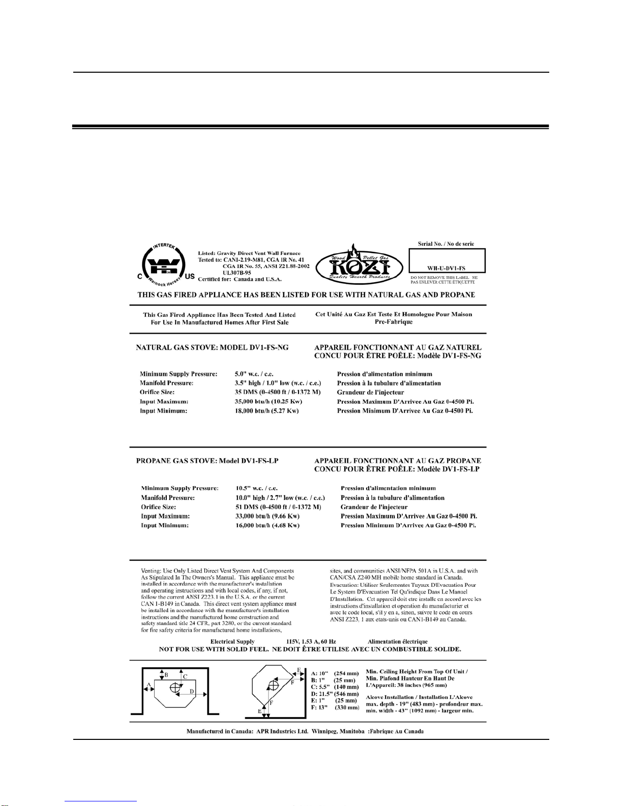
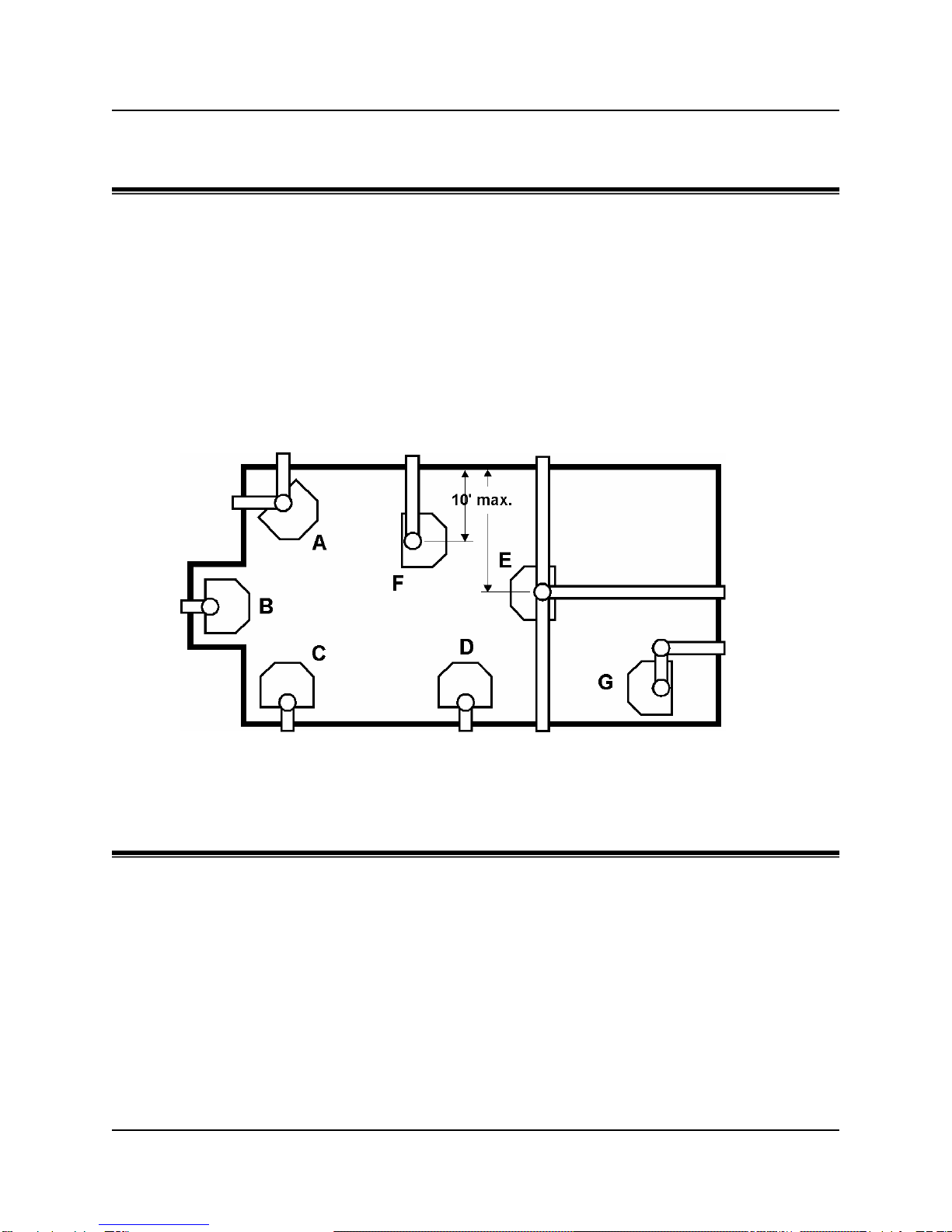
•TheKOZI DirectVentFreestandingGasStove has been approvedfortheinstallations
displayed in the following diagram, Fig. 3. This unit has also been approved for
installations employing millivolt thermostats for heat regulation. Installations in Mobile
Homes have been approved as long as the appliance is securely bolted to the frame.
•The installation must conform with local codes or, in the absence of local codes, with
the National Fuel Gas Code, ANSI Z223.1/NFPA 54, or the Natural Gas and Propane
Installation Code, CSA B149.1. A manufactured home (USA only) or mobile home
OEM installation must conform with the Manufactured Home Construction and Safety
Standard, Title 24 CFR, Part 3280, or, when such a standard is not applicable, the
StandardforManufacturedHome installations,ANSI/NCSBCSA225.1,orStandard for
Gas Equipped Recreational Vehicles and Mobile Housing, CSA Z240.4.
•The appliance, when installed, must be electrically grounded in accordance with local
codes or, in the absence of local codes, with the National Electrical Code, ANSI/NFPA
70, or the Canadian Electrical Code, CSA C22.1. This appliance is equipped with a
three-prong (grounding) plug for your protection against shock hazard and should be
pluggeddirectly into a properlygroundedthree-prongreceptacle. Donotcutorremove
the grounding prong form this plug.
•The product should be inspected for shipping damage prior to installation and serviced
annually thereafter by a qualified technician.
•This appliance must be connected to the specified vent and termination cap to the
outside of the building. Never vent into another room or inside a building. Ensure that
the vent is properly jointed as per the instruction on page 17.
•To prevent injury or bodily harm, do not allow anyone who is unfamiliar with this
appliance operate it without supervision.
•The efficiency rating of this appliance is a product thermal efficiency rating determined
under continuous operating conditions and was determined independently of any
installed system.
Note: Read these instructions carefully and completely. Failure to follow
them could cause malfunction or damage to the appliance, property
damage, personal injury or fatality. Failure to comply with these
instructions could result in loss of insurance coverage and warranty.

KOZI DIRECT VENT GAS STOVE
8
•The appliance and it’s appliance main gas valve must be disconnected from the gas
supply piping system during any pressure testing of that system at test pressures in
excess of ½ psi (3.5 kPa)
•The appliance must be isolated from the gas supply piping system by closing it’s
equipment shutoff valve during any pressure testing of the gas supply piping system at
test pressures equal to or less than ½ psi (kPa).
•Installation and repair should be done by a qualified service person. The appliance
should be inspected before use and at least annually by a professional service person.
More frequent cleaning may be required due to excessive lint from carpeting, bedding
material, et cetera. It is imperative that control compartments, burners and circulating
air passageways of the appliance be kept clean.

KOZI DIRECT VENT GAS STOVE
9
LOCATING YOUR KOZI GAS STOVE
Allclearanceslistedbelowandwithin the following section mustbesatisfiedwhenselecting
a location for your appliance. Maintaining these clearances will ensure that there will be
adequate access for servicing and regular maintenance.
This unit has been approved for the following locations in your dwelling:
A. Angled Across Corner
B. Flush Against Wall And Alcove
C. Flat Against Wall And Corner
D. Flat Against Wall
E. Island Installation
F. Dividing Room
G. Two Elbow Venting
Figure: 3 - Various Approved Installation Configurations
CLEARANCES TO COMBUSTIBLE SURFACES
Thelistofclearances provided are MINIMUM distances only. Measure the clearance area
to both theappliance and the chimney connector. Thegreatermeasurement is correctifthe
two clearances do not coincide.
For example, if the unit is situated as indicated in Fig. 3 but the connector is too close,
move the unit until the correct clearance is achieved.
This appliance may only be installed with the clearances provided as shown in Figs. 3 & 4.
DO NOT combine clearances from one type of installation with another to achieve closer
clearances.

KOZI DIRECT VENT GAS STOVE
10
Usetheminimumclearances provided below with the appropriate dimension shown inFig.
2, also below.
A. Side Wall To Unit 10” (254 mm)
B. Back Wall To Unit 1” (25 mm)
C. Back Wall To Flue Centreline 5.5” (140 mm)
D. Side Wall To Flue Centreline 21.5” (546 mm)
E. Side Wall To Unit 1” (25 mm)
F. Side Wall To Flue Centreline 9” (228 mm)
Figure: 4 - Minimum Clearances Diagram.
COMBUSTION AND VENTILATION AIR
VENTING
The instructions contained within the pages of this manual pertain to the installation of
Simpson Dura-Vent Direct Vent System model DV-GS. This venting system, in
combinationwiththeKOZI Direct Vent Freestanding Gas Stove, DV1,havebeentested
and listed as a direct vent space heater by Warnock Hersey.
Note: The fresh combustion air required by this gas stove is drawn from
outside the building through the outer flue. Therefore, there is no need for extra
provisions to increase the air inside the room containing the appliance.
Minimum ceilin
g
clearance hei
g
ht is 38”
(
965 mm
)
from the to
p
of the unit.

KOZI DIRECT VENT GAS STOVE
11
Note: The location of the termination cap must satisfy the requirements set forth by the
Exterior Vent Terminal Locations found in Fig. 3, on the next page.
INSTALLATION PRECAUTIONS:
The Simpson Dura-Vent Direct Vent System is an engineered product that has been
Designed and thoroughly tested for use with the KOZI DV1. The Simpson Dura-Vent
warranty will be voided and serious fire, health and safety hazards may result from any of
the following situations:
1. The utilization of any damaged Direct Vent component.
2. Unauthorized modification or alteration of any kind to the
Direct Vent System.
3. Unauthorized installation of any Direct Vent System
components not manufactured or approved by Simpson
Dura-Vent and or APR Industries Ltd.
4. Installation other than as instructed in this manual or by
Simpson Dura-Vent.
IMPORTANT:
Carefully Read All Instructions To Completion Prior To Installation. Failure To
Follow These Instructions May Result In Safety Hazards, As Well As Voiding
The Warranty. Ensure That All Venting And Clearances To Combustible
Requirements Have Been Satisfied. Consult Your Local Building Codes
Before You Begin The Installation.
WARNING
Always maintain required clearances to nearby combustibles to aid in the
prevention of fire and safety hazards. Do not fill air spaces with insulation or any
other combustible material.
The minimum clearance requirements between the outer wall of the vent pipe
andnearbycombustiblesurfacesis1¼”. Ensure that the ventterminalclearance
requirements from decks, windows, soffits, gas regulators, air supply inlets and
public walkways have been satisfied completely. The diagram on the following
page, Fig. 5, demonstrates these clearance requirements, or alternately refer to
your local building codes.

KOZI DIRECT VENT GAS STOVE
12
Figure: 5 - Vent terminal minimum clearance requirements.

KOZI DIRECT VENT GAS STOVE
13
VENTING CONFIGURATIONS:
HORIZONTAL TERMINATION
The shaded area on the following diagram, Fig. 6, illustrates the allowable configuration
and variations when installing venting with a horizontal termination.
Figure: 6 - Illustration of allowable horizontal venting configurations.
Example:
A 10 foot vertical rise with a 10 foot horizontal run falls within the shaded area, and
therefore, is an allowable installation.
Additionally, vent configuration consisting of a 3footminimumverticalventheightfollowed
by a 90 degree elbow, maximum 2 feet horizontal vent run, another 90 degree elbow and
another maximum of 2 feet horizontal vent run is also a tested and approved installation.

KOZI DIRECT VENT GAS STOVE
14
VENTING CONFIGURATIONS:
VERTICAL TERMINATION
The shaded areas of the two diagrams below illustrate the allowable venting configuration
when installing straight vertical or offset vertical venting utilising a vertical venting
termination cap.
Figure: 7 - Illustration of allowable vertical venting configurations.
Examples:
•Venting with vertical termination. A 10-foot vertical rise falls within the shaded
area, and therefore is an allowable venting configuration.
•Venting with an offset to vertical termination. A 15-foot vertical rise with a 4-foot
horizontal offset distance falls within the shaded area and is an allowable venting
configuration.
A
ll Vertical And Offset Vertical Vent Installations Require The Use Of The
SimpsonDura-VentVentRestrictor. If The Venting Is Enclosed In A Chase,
(Minimum Size Of 9” X 9”), Maintain A 1¼” Clearance To All Combustibles.
ATTENTION:
All vertical
applications must
use the HIGH WIND
TERMINAL.

KOZI DIRECT VENT GAS STOVE
15
PLANNING YOUR INSTALLATION
As mentioned on the previous pages, there are basically two types of Direct Vent System
installations: vertical and horizontal termination. Confirm that the desired installation is
allowed by referencing the maximum vertical riseandmaximumhorizontalrun with Figs. 6-
7.
During the process of planning your venting installation, you will be required to know the
proper vent length to select according to your specific needs. For horizontal installations,
determine the minimum clearance from the rear of the unit to the wall. Remember to take
into consideration the thickness of the wall itself. All horizontal venting must have a ¼”
rise per foot of run towards the terminal cap. Determine the amount of vertical rise
required for "vertical-to-horizontal" type installations.
When working with vertical installations, determine the length of vent pipe required by
measuring the distance from the unit flue outlet to the ceiling, the ceiling thickness, the
vertical rise in the attic or second story, andanallowancetosatisfy clearance requirements
above the roofline.
If the application calls for a two story “through the floor” installation, the use of fire stops
is mandatory at each floor level. Additional pipe and elbows will be required if an offset
is needed. Venting terminals shall not be recessed into a wall or siding.
IMPORTANT
The Gas Appliance And Venting System Must Be Vented Directly To The
Outside Of The Building, In Accordance With All Regulatory Requirements,
And Never Be Attached To A Chimney Serving A Separate Solid Fuel Or Gas
Burning Appliance. Each Direct Vent Appliance Must Use Its Own Separate
Vent System. Common Vent Systems Are Prohibited.
All Venting Installations Using Simpson Dura-Vent Direct Vent System
Model DV-GS, Must Be In Compliance With The Venting Instructions And
Requirements Specified By Simpson Dura-Vent.
Safety Precautions For The Installer:
1. Wear Gloves And Safety Glasses For Protection.
2. Exercise Extreme Caution When Using Ladders Or
Working On Roof Tops.
3. Make Yourself Aware Of The Locations Of All
Electrical Wiring Within The Walls And Ceiling.

KOZI DIRECT VENT GAS STOVE
16
SIMPSON DURA-VENT DIRECT VENT
PARTS LISTING
The Simpson Dura-Vent Direct Vent System offers a complete line of component parts for
all types of installations requirements. Many items are offered in decorative black or
galvanizedfinishes. Thegalvanizedpipeandfittings are usedforconcealedlocationssuch
as attics or in areas where corrosion is a consideration, such as above the roofline.
Decorative trim kits are available for both wall thimbles and ceiling support boxes in brass
or chrome.
Simpson DV Part # Description
971 Horizontal Termination Kit A
973 Vertical Termination Kit
950 Vinyl Siding Standoff Kit
942 Wall Thimble
908B 6” Pipe Length (Black Finish)
907B 9” Pipe Length (Black Finish)
906 12” Pipe Length (Galvanized)
906B 12” Pipe Length (Black Finish)
904 24” Pipe Length (Galvanized)
904B 24” Pipe Length (Black Finish)
903 36” Pipe Length (Galvanized)
903B 36” Pipe Length (Black Finish)
902 48” Pipe Length (Galvanized)
902B 48” Pipe Length (Black Finish)
911B 11” – 14 5/8” Adjustable Pipe Length
945 45° Elbow (Galvanized)
945B 45°Elbow (Black Finish)
990 90°Elbow (Galvanized)
990B 90°Elbow (Black Finish)
981 Snorkel Termination Cap 36”
982 Snorkel Termination Cap 14”
984 Horizontal Square Termination Cap
991 Vertical Termination Cap
940 Round Ceiling Support Box / Wall Thimble
941 Cathedral Ceiling Support Box
953 Storm Collar
963 Fire stop Spacer
988 Wall Strap
929 Restrictor Disc
Note: Simpson Dura-Vent reserves the right to change the above listing without notice.
For current listings, contact your local Simpson Dura-Vent dealer.

KOZI DIRECT VENT GAS STOVE
17
VENT RESTRICTOR
Ventrestrictorsarerequiredincertain venting applications. This restrictormustbeinstalled
before connecting the vent pipe to vent terminal.
Referring to the figure below, slide the restrictor into the inner flue pipe and bend the side
tabs appropriately to secure the part. Examine the following diagram for further detail.
Figure: 8 - Drawing of venting restrictor and placement.
HORIZONTAL TERMINATION INSTALLATIONS
1. Set the unit in the desired location, this location must satisfy all applicable
codes and regulations. Check to determine if wall studs and roof rafters are
clear of the venting path. Adjust the unit accordingly.
2. SimpsonDura-VentDirectVentpipeand fittings aredesignedwithspecialtwist
lock connections for attaching the appliance flue outlet to the venting system.
This special twist lock adapter has been installed on the appliance from the
factory.Assemblethedesiredcombinationofpipe and elbows to theappliance
adapter with pipe seams facing towards the wall or ceiling, depending on
application.
Twist Lock Procedure
Four indentations, located on thefemaleendsofthepipes and fittings, aredesigned
to slide straight into the male ends of adjacent pipes and fittings. Align the four
indentationssothatthey matchthe four entry slots on the male ends,andthenslide
into slots. Push the pipe sections tightly together, then twist lock one section
clockwise ¼ turn, until a complete lock is achieved.

KOZI DIRECT VENT GAS STOVE
18
3. With the pipe attached to the stove, slide the unit into its correct location
and mark the wall for a 10" x 10" square hole. The centre of the hole
should coincide with the centreline of the horizontal incorporating the
required inclination. Cut and frame the hole in the exterior wall where
the vent will be terminated.
4. Applyathinbead of non-hardening masticaroundtheouteredgesofthe
terminal to ensure a tight seal between the Stand-off and the terminal.
Attach the Vinyl Siding Stand-off, if required, to the Horizontal Vent
Terminal. Install the vinyl siding stand-off between the vent cap and the
exterior wall and attach with the four woodscrewsprovided.Sealaround
the vinyl stand-off on all four sides. The arrow on the exterior of the vent
cap should be pointing upwards. Ensure that all clearances have been
maintained. (The four wood screws should be substituted with the
appropriate fastener particular to your buildings exterior finish.)
5. Prior to connecting the horizontal run of vent pipe to the vent terminal,
slide the decorative wall thimble cover over the pipe, and attach with
wood screws.
6. Slide the appliance and vent assembly towards the wall, carefully
inserting the vent pipe into the vent cap assembly. It is important to
insure that the vent pipe fits into the vent cap by a minimum overlap of
1-1/4 inches. Secure the connection between the vent pipe and the vent
cap by attaching the sheet metal strips extending from the vent terminal
assembly into the outer wall of the vent pipe. Use the two sheet metal
screws provided for attaching the pipe and strapping. Bend any
remaining strapping back towards the vent cap to conceal it behind the
wall thimble.
NOTE: Horizontal runs of venting must be supported every three
feet. Wall strapping kits are available for this purpose.
NOTE: The horizontal run must possess a ¼” rise per foot of run
towards the terminator. Never allow the venting to run downwards.
This situation could cause excessive temperature build up and
present the possibilit
y
of fire and safet
y
hazards.
NOTE: The venting terminal shall never be recessed into a wall or
siding. The vinyl siding standoff kit is not mandatory on all
horizontal termination installations, only when the exterior of the
buildin
g
possesses a vin
y
l sidin
g
finish.

KOZI DIRECT VENT GAS STOVE
19
7. Slide the decorative wall thimble up the wall surface and attach with
screws provided. Apply the decorative brass or chrome trim kits if
desired.
VERTICAL TERMINATION INSTALLATIONS
1. Insure that the 1-1/4 inch clearances have been maintained to
combustibleswhenpassingthroughceilings,walls, roofs, enclosures or
attic rafters. Do Not pack air gaps with insulation. Refer to Fig. 7 for
verification of maximum vertical rise of venting system and maximum
horizontal offset limitations.
2. Set the gas appliance in its appropriate location. Use a drop plumb line
from the ceiling to locate exactly the appliance flue exit. Mark the
location where the flue will penetrate the ceiling. Drill a pilot hole at this
location. Now drop a plumb line from the roof to the hole previously
drilled in the ceiling, and mark the spot where the vent will penetrate the
roof. To avoid having to cut any load bearing members of the roof
rafters or ceiling joists, insure they are all out of the path of the venting.
You may wish to offset the venting or relocate the appliance to
accommodate these clearances.
3. To install the Round Support Box / Wall Thimble in a flat ceiling, cut a
10 inch square hole in the ceiling centred on the hole drilled in the
previous step. Frame in the hole from the exterior surface.
4. Assemble the desired lengths of venting pipe and elbows necessary to
reach from the appliance adapter up through the Round Support Box.
Insure that all pipes and elbow connections are in the fully twist locked
position and sealed.
5. Cut a hole in the roof centred on the small drilled hole placed in the roof
during step 2. The hole should be of sufficient size to meet the minimum
requirements for clearances to combustibles. Continue to assemble the
lengths of pipes and elbows necessary to reach from the ceiling support
boxupthroughthe roofline. Galvanized pipe and elbows may be used in
the attic as well as above the roofline. The finish of galvanized pipe is
more desirable above the roofline due to its higher corrosion resistance
properties.
6. Slip the flashing over the pipe sections protruding through the roof.
Secure the base of the flashing to the roof with roofing nails. Insure the

KOZI DIRECT VENT GAS STOVE
20
roofing material overlaps the top edge of the flashing. Verify that the
minimum clearance to combustibles is maintained at the roof line. Slide
the storm collar over the pipe section and seal.
7. Continue to add pipe sections until the height of the vent cap meets the
minimum building code requirements described in the following chart,
Roof Pitch Vent Height Table. Note that for steep roof pitches, the vent
height must be increased. A poor draft, or down draft, can result from
high wind conditions, nearby trees, adjoining rooflines, steep pitched
roofs, and other similar factors. In these cases, increasing the vent
height may resolve the problem. Twist lock the vent terminal.
NOTE: If an offset is necessary in the attic to avoid obstructions, it is
important to support the vent pipe every three feet to avoid excessive
stress on the elbows. Wall strapping kits are available for this purpose.
NOTE: For multi-story vertical installations, a ceiling fire stop is
required at the second floor, and each subsequent floor thereafter.
The opening should be framed to 10” x 10” square inside
dimensions.
Any occupied areas in the first floor, including closets and storage
spaces, through which the venting passes, must be enclosed. The
enclosure may be framed and paneled with standard building
materials. DO NOT fill in any of the required air gaps with insulation.
Table of contents
Other Kozi Stove manuals