2
Table of Contents
1.
General Description.......................................................................................................................................5
1.1
Introduction...................................................................................................................................................5
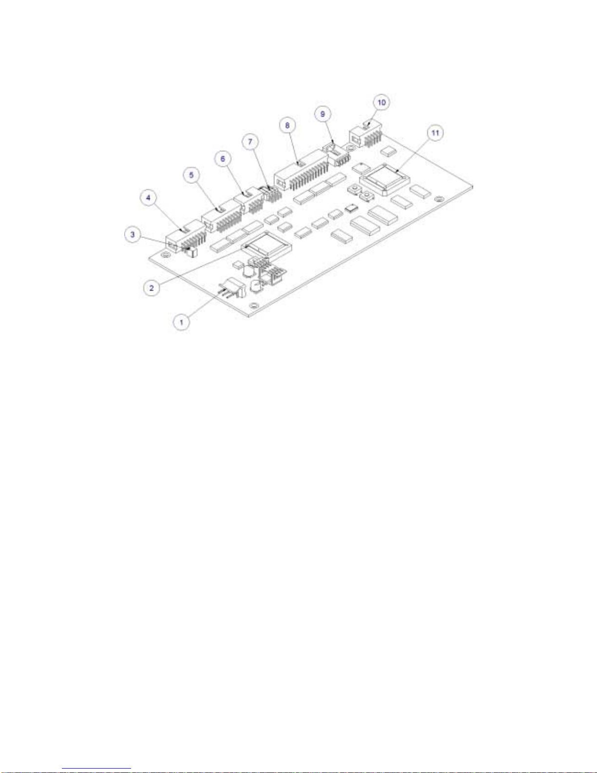
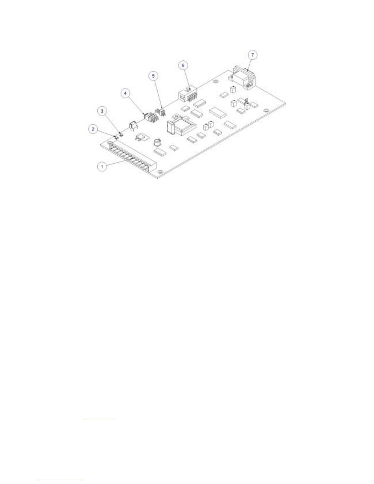
1.2
Physical Description......................................................................................................................................5
1.3
Principal of Operation..................................................................................................................................8
2.
RCI5000 panels Description........................................................................................................................10
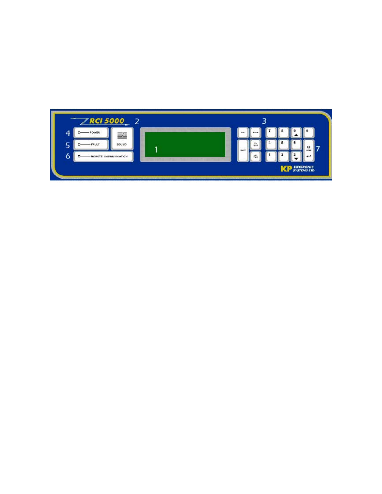
2.1
Front Panel..................................................................................................................................................10
2.1.1
LEDs...............................................................................................................................................10
2.1.2
Keypad............................................................................................................................................11
2.1.3
LCD ................................................................................................................................................11
2.2
Rear Panel ...................................................................................................................................................11
2.3
Power Connection and States.....................................................................................................................12
2.4
Power On Self Test (POST)........................................................................................................................13
3.
RCI5000™ Operation..................................................................................................................................13
3.1
Setup.............................................................................................................................................................15
3.2
RCI5000 Parameters and setup using front panel...................................................................................15
3.2.1
Setting Clock and Date...................................................................................................................16
3.2.2
General Setup .................................................................................................................................16
3.2.2.1
Set New RCI5000 ID Number ................................................................................16
3.2.2.2
Set Buzzer ON/OFF ................................................................................................16
3.2.3
Ports Setup......................................................................................................................................17
3.2.3.1
COM Setup .............................................................................................................17
3.2.3.2
USB Setup...............................................................................................................17
3.2.3.3
Printer (PRN) Setup ................................................................................................18
3.2.4
Channel Setup ................................................................................................................................18
3.2.4.1
Set Protocol .............................................................................................................18
3.2.4.2
Message Filter Setting.............................................................................................19
3.2.4.3
System Address Selectivity Setup...........................................................................19
3.2.4.4
Account Number Selectivity Setup .........................................................................19
3.2.4.5
System Address Mask Setting.................................................................................20
3.2.4.6
Channel Quiet Time Setting....................................................................................20
3.2.4.7
Channel Busy Time Setting.....................................................................................20
3.3
Setup RCI5000 using GUP5000™ - General Utility PC software ..........................................................21
3.3.1
Hardware Connection.....................................................................................................................21
3.3.2
GUP5000 software and database information................................................................................22
3.3.3
How to use GUP5000 for RCI5000 parameters setup ...................................................................22
3.3.4
Set and Program parameters...........................................................................................................24
3.3.4.1
General parameters..................................................................................................25
3.3.4.2
Ports parameters......................................................................................................26
3.3.4.3
Channel parameters.................................................................................................27
3.4
Browsing Incoming Message Buffer..........................................................................................................27
3.5
Browsing Two-Way units Buffer...............................................................................................................28
3.6
Tests..............................................................................................................................................................28
3.6.1
Printer Test .....................................................................................................................................29
3.6.2
Buzzer Test.....................................................................................................................................29
3.7
System Information.....................................................................................................................................29