Kracht VCA 0.04 User manual

Gear-type flow meter VCA/VCN/VCG
English
11 • 18/08/2021
Operating instructions (Translation)

Table of content Kracht GmbH
ii 88025530002-11
Table of content
1 General ................................................................................................................................................................4
1.1 About the documentation ....................................................................................................................................................... 4
1.2 Manufacturer address................................................................................................................................................................ 4
1.3 Symbols........................................................................................................................................................................................... 5
2 Safety...................................................................................................................................................................6
2.1 Intended use.................................................................................................................................................................................. 6
2.2 Personnel qualification and training.................................................................................................................................... 6
2.3 Basic safety instructions............................................................................................................................................................ 7
2.4 Fundamental hazards.................................................................................................................................................................7
3 Device description.............................................................................................................................................. 9
3.1 Functional principle .................................................................................................................................................................... 9
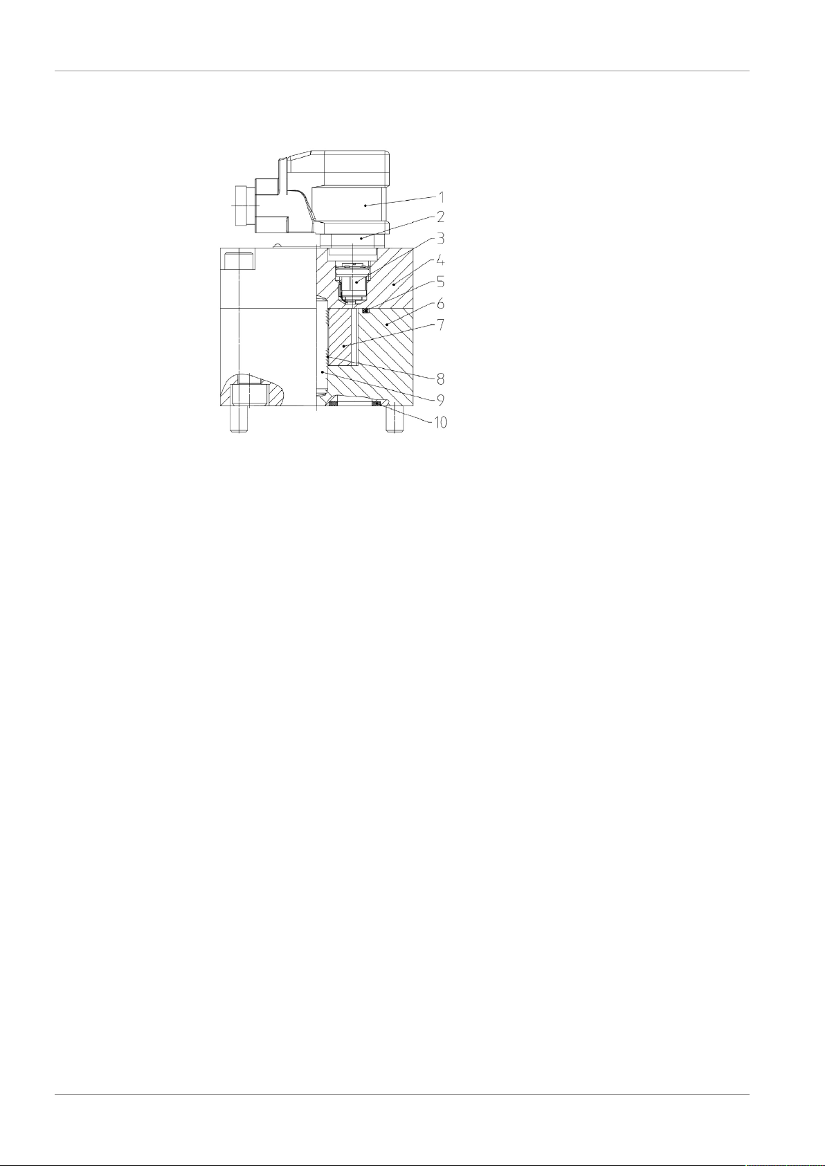
3.2 Basic design.................................................................................................................................................................................10
3.3 Type key ........................................................................................................................................................................................11
3.4 Special numbers.........................................................................................................................................................................12
4 Technical data...................................................................................................................................................13
4.1 General ..........................................................................................................................................................................................13
4.2 Overview nominal sizes...........................................................................................................................................................14
4.3 Permissible temperature range............................................................................................................................................15
4.4 Material data ...............................................................................................................................................................................15
4.5 Weight ...........................................................................................................................................................................................16
4.6 Dimensions ..................................................................................................................................................................................16
5 Transport and storage .....................................................................................................................................17
5.1 General ..........................................................................................................................................................................................17
5.2 Transport.......................................................................................................................................................................................17
5.3 Storage ..........................................................................................................................................................................................17
5.4 Storage conditions....................................................................................................................................................................18
6 Installation ........................................................................................................................................................19
6.1 Important notes about explosion protection.................................................................................................................19
6.2 Mechanical installation............................................................................................................................................................20
6.2.1 Preparation....................................................................................................................................................................20
6.2.2 Plate connection ........................................................................................................................................................21
6.2.3 Pipe connection...........................................................................................................................................................23
6.3 Electrical connection ................................................................................................................................................................23
6.3.1 Preamplifier (S, H , K).................................................................................................................................................23
7 Operation start-up ...........................................................................................................................................25
7.1 Safety instructions for start-up ............................................................................................................................................25
7.2 Preparation...................................................................................................................................................................................25
7.3 Further operation start-up.....................................................................................................................................................25

Kracht GmbH Table of content
88025530002-11 iii
8 Removal.............................................................................................................................................................27
8.1 Safety instructions for removal ............................................................................................................................................27
8.2 Removal.........................................................................................................................................................................................28
9 Maintenance .....................................................................................................................................................29
9.1 Safety instructions for maintenance ..................................................................................................................................29
9.2 Maintenance work.....................................................................................................................................................................30
9.2.1 Cleaning - Desposits in the measuring device................................................................................................30
9.3 Maintenance instructions.......................................................................................................................................................31
9.4 Maintenance table ....................................................................................................................................................................32
9.4.1 Maintenance table......................................................................................................................................................32
9.4.2 Inspection: Discharge flow ......................................................................................................................................33
9.4.3 Inspection: Operating pressure.............................................................................................................................33
9.4.4 Inspection: Media temperature ............................................................................................................................33
9.4.5 Inspection: Check the potential compensation (if existing)....................................................................... 33
9.4.6 Inspection: Condition of operating fluid ..........................................................................................................33
9.4.7 Audiometric monitoring: Unusual noise............................................................................................................33
9.4.8 Cleaning..........................................................................................................................................................................33
9.4.9 Visual inspection: Leakages ....................................................................................................................................33
9.4.10 Inspection: Device temperature ............................................................................................................................34
9.4.11 Visual inspection: Measuring unit status...........................................................................................................34
9.4.12 Visual inspection: Condition of housing parts.................................................................................................34
9.4.13 Visual inspection: Bearing status ..........................................................................................................................34
9.4.14 Replace: Other seals...................................................................................................................................................34
9.4.15 Cleaning Desposits in the measuring device...................................................................................................34
10 Repairs...............................................................................................................................................................35
10.1 Safety instructions for repair.................................................................................................................................................35
10.2 General ..........................................................................................................................................................................................36
10.3 Detecting and eliminating failures......................................................................................................................................37

1 | General Kracht GmbH
4 / 37 88025530002-11
1 General
1.1 About the documentation
These operating instructions describe the installation, operation and maintenance of the fol-
lowing device:
Gear type flow meter VCA / VCN / VCG
These operating instructions are a component of the device and must be kept accessible for
the personnel near the device at all times.
The device is manufactured in different versions. Information about the version concerned in
the individual case can be found on the device's type plate.
If you have any questions about these operating instructions, please contact the manufac-
turer.
1.2 Manufacturer address
KRACHT GmbH
Gewerbestraße 20
DE 58791 Werdohl
Tel: +49 2392 935-0
Fax: +49 2392 935-209
E-Mail: [email protected]
Web: www.kracht.eu

Kracht GmbH General | 1
88025530002-11 5 / 37
1.3 Symbols
DANGER
Identification of an immediate hazard, which would result in death or severe bodily injury if
not avoided.
WARNING
Identification of a potential medium risk hazard, which would lead to death or severe bodily
injury if not avoided.
CAUTION
Identification of a low risk hazard, which could lead to minor or medium bodily injury if not
avoided.
ATTENTION
Flagging of notices to prevent property damage.
NOTICE
Identification of basic safety instructions.
Non-compliance can lead to hazards for people and the device.
TIP
Flagging of special user tips and other especially useful or important information.

2 | Safety Kracht GmbH
6 / 37 88025530002-11
2 Safety
2.1 Intended use
1. The device has been designed for operation with fluid.
Dry operation is not permitted.
2. The product may only be operated when completely filled.
3. The fluid must be compatible with the materials used in the product. Chemical expertise
is required for that. Be careful with ethylene oxide or other catalytically or exothermically
reacting or self-decomposing substances. Please consult the manufacturer in cases of
doubt.
4. The product may only be used in normal industrial atmospheres.
If there are any aggressive substances in the air, always consult the manufacturer.
5. The product may only be operated in compliance with these operating instructions and
the applicable documents.
Deviating operating conditions require the express approval of the manufacturer.
6. Use of the product for purposes other than those for which it is intended invalidates any
warranty.
2.2 Personnel qualification and training
The personnel designated to assemble, operate and service the device must be properly
qualified.
This can be through training or specific instruction.
Personnel must be familiar with the contents of this operating instructions.
NOTICE
Read the operating instructions thoroughly before use.

Kracht GmbH Safety | 2
88025530002-11 7 / 37
2.3 Basic safety instructions
NOTICE
Basic safety instructions
Non-compliance can lead to hazards for people and the unit.
a) Follow existing regulations for accident prevention and safety at work as well as the in-
ternal regulations of the operating company.
b) Ensure the greatest possible cleanliness.
c) Wear suitable personal protective equipment.
d) Do not remove type plates or other information or make them illegible or unrecognis-
able.
e) Do not make any technical modifications.
f) Comply with maintenance intervals.
g) Only use spare parts approved by the manufacturer.
2.4 Fundamental hazards
DANGER
Hazardous fluids
Danger to life when handling hazardous fluids.
a) Comply with the safety data sheets and regulations on handling the hazardous fluids.
b) Collect and dispose of hazardous fluids so that no hazard is created for persons or the
environment.
DANGER
Rotating parts!
Danger of death due to body parts, hair or clothing getting trapped or entangled.
a) Before all work, ensure that existing drives are voltage-free and pressure-free.
b) Securely prevent restarting during all work.
DANGER
Exposed electrical components
Risk of fatal electric shock.
a) Adhere to the special safety regulations for all work on electrical systems.
Switch off electrical systems and secure them against being switched on again.
b) Work on electrical systems may only be carried out by a qualified electrician.
c) Use only connection lines that are resistant to ambient influences and media.

2 | Safety Kracht GmbH
8 / 37 88025530002-11
WARNING
Failure of pressure bearing parts due to overload
Risk of injury from flying parts.
Risk of injury due to splashing fluids.
a) Depressurize the system before all work.
b) Securely prevent the pressure from being restored during work.
WARNING
Failure of pressure bearing parts due to overload
Risk of injury from flying parts.
Risk of injury due to fluid spurting out.
a) Use only connections and lines approved for the expected pressure range.
b) Securely prevent the permissible pressures from being exceeded, e.g. by using pressure
relief valves or bursting discs.
c) Pipelines must be designed in such a way that no tension e.g. caused by changes in
length due to fluctuations in temperature can be transferred to the product.

Kracht GmbH Device description | 3
88025530002-11 9 / 37
3 Device description
3.1 Functional principle
The measuring unit is driven by the flow of fluid based on the principle of a gear motor.
The gears run in a contactless manner in the measuring chamber. The lowfriction bearings or
plain bearings act as the bearing elements.
The gear movement is sampled in a contactless manner through the sensors installed in the
cover. There is a pressure-resistant amagnetic division between the sensor space and meas-
uring chamber.
During the rotation of the measuring unit by one tooth pitch, a signal occurs per sensor that
corresponds to the so-called geometric tooth volume of Vgz. A value that is stated in tech-
nical documents as the nominal volume to specify the unit size.
The 1-channel scan measures the flow but does not recognise its direction.
The two-channel scanning facilitates a higher measuring resolution and detection of the dir-
ection of the flow rate.
In the gear type flow meter, the drive direction of the flow of fluid is independent of the dir-
ection.

3 | Device description Kracht GmbH
10 / 37 88025530002-11
3.2 Basic design
1 Cable socket 6 Housing
2 Equipment plug 7 Gears
3 Sensor 8 Plain bearing bush
4 Cover 9 Bearing journal
5 O-ring 10 O-ring

Kracht GmbH Device description | 3
88025530002-11 11 / 37
3.3 Type key
Ordering example
VCA 0.2 K 4 F 4 P 2 S H
1. 2. 3. 4. 5. 6. 7. 8. 9. 10. 11.
Explanation of type key
1. Product name
VCA; VCN; VCG
2. Nominal size ( Rated volume)
Vgz 0.04; 0.1; 0.2; 2; 5
3. Bearing
KBall bearing MMulti layer friction bearings
UPlastic plain bearings
4. Material
1
Housing: EN-GJS-400-15
(GGG-40)
Gears: Steel
2Housing: Stainless steel
Gears: Stainless steel
4Housing: Aluminium
Gears: Stainless steel 5Housing: Aluminium
Gears: Steel
5. Seal
FFKM PFEP
NNBR
6. Surface
1painted 4hardcoated
3Without 5anodized
7. Type of connection
PPlate structure RPipe connection
8. Sensor system
11 Sensor 3Without
22 Sensors 4
2 Sensors
protected against vibration and
condensation
9. Electronics
SStandard Vwithout preamplifier (for Plug-in
display unit SD 1)
KHigh temperature PLUS
10. Cable length
Without Cable 5With 5 m Cable
2With 2 m Cable 10 With 10 m Cable
11. Electrical connection
HEquipment plug/socket (Standard) MEquipment plug/socket (M12x1)
VWithout

3 | Device description Kracht GmbH
12 / 37 88025530002-11
3.4 Special numbers
Special number Description
40 Housing connection:
VCA 2...:Whitworth pipe thread G 1"

Kracht GmbH Technical data | 4
88025530002-11 13 / 37
4 Technical data
4.1 General
General information
Design Gear motor
Housing connection (1) Plate structure / Pipe thread
Mounting position Any
Flow direction Any
Viscosity
Overview nominal sizes [}14]Operating pressure p
Permissible pressure loss Δpmax
Fluid temperature ϑmPermissible temperature range [}15]
Ambient temperature ϑu
Material Material data [}15]
Measuring accuracy
Overview nominal sizes [}14]
Permissible size of foreign particles in the
medium
Permissible media
Lubricating fluids without abrasive compon-
ents. The medium must be compatible with
the materials used in the device.
(Please consult the manufacturer in cases of
doubt)

4 | Technical data Kracht GmbH
14 / 37 88025530002-11
4.2 Overview nominal sizes
Product name VCA VCN VCA VCA VCN VCA VCN VCA VCG
Nominal size(1) 0.04 0,1 0.2 2 5
Geom. tooth
volume Vgz [cm³/r] 0.04 0,1 0.2 2 5.222
Resolution [pulse/l] 25000 1000
00 5000 500 191.5
Max. operating
pressure [bar] 200 160 200 160 160 315 80 315
Pressure peaks [bar] 240 190 240 200 200 350 100 350
Perm. number of load alterna-
tions of the peak pressure - 1x10⁶
Measuring
range(2) [l/min] 0.02…4 0.08…
10 0.25…10 1…65 1…
200
3…
240
Max. pressure
loss [bar] 10 16
Measuring accuracy
starting from viscosity in
mm²/s
± 2%
20
± 3%
20
± 2.5%
20
± 1%
20
±
2.5%
20
Viscosity mm²/s 20….4000 1…3000
Lubricating properties of the
operating fluid good
Sound pressure
level LpA [dBA] < 60
(1) See type key and type designation at device
(2)The measuring range may be restricted at higher pumping medium viscosity.
Nominal size Permissible size of foreign particles in the medium [µm]
Product name
VCA VCN VCG
0.04
30
30
-0.1 -
0.2 30
2-30
520 20

Kracht GmbH Technical data | 4
88025530002-11 15 / 37
4.3 Permissible temperature range
Sealing material Fluid temperature ϑm
(1)
ϑm min [°C] ϑm max [°C]
FKM
-10
VCG: -15
80
VCG: 120
EPDM
FEP with FKM-core (till
2019)
FEP with silicone-core (from
2020)
(1) Comply with media-specific properties
Sealing material Ambient temperature ϑu
ϑu min [°C] ϑu max [°C]
FKM
-10
VCG: -15
80
VCG: 120
EPDM
FEP with FKM-core (till
2019)
FEP with silicone-core (from
2020)
4.4 Material data
Product name VCN VCG
Nominal size 0.04 0.2 2 5
Bearing K U U M M
Material 4 4 5 5 5
Mater-
ial
Hous-
ing /
Cover
Stainless steel (1.4462) EN-GJS-400-15 (GGG-40)
Meas-
uring
unit
Stainless steel
(1.4462)
Stainless steel
(1.4462) Case-hardened steel (1.7139)
Bearing Anti-friction
bearing steel Iglidur® X Steel , sintered bronze ,
PTFE
Bearing
pin
Stainless steel
(1.4462)
Stainless steel
(1.4462) Hardened steel
Type of bearing Ball bearing Plastic plain bearings Multi layer friction bear-
ings

4 | Technical data Kracht GmbH
16 / 37 88025530002-11
Product name VCA
Nominal size 0,4 0,1 0,2 2 5
Bearing K K U U M U K K
Material 45445454
Mater-
ial
Hous-
ing /
Cover
Aluminium
Al Mg Si F30
Aluminium
Al Mg Si F30
(hardcoated)
Meas-
uring
unit
Stain-
less
steel
(1.4462)
Case-
hardene
d steel
(1.7139)
Stainless steel
(1.4462)
Case-
hardene
d steel
(1.7139)
Stain-
less
steel
(1.4462)
Case-
hardene
d steel
(1.7139)
Stain-
less
steel
(1.4462)
Bearing Anti-friction
bearing steel Iglidur® X
Steel,
sintered
bronze,
PTFE
Iglidur®
X
Anti-friction
bearing steel
Bearing
pin
Stain-
less
steel
(1.4462)
Hardene
d steel
Stainless steel
(1.4462)
Hardene
d steel
Stain-
less
steel
(1.4462)
Hardene
d steel
Stain-
less
steel
(1.4462)
Type of bearing Ball bearing Plastic plain bear-
ings
Multi
layer
friction
bearings
Plastic
plain
bearings
Ball bearing
4.5 Weight
Nominal size Product name Weight [kg]
Pipe connection Plate structure
0,04 VCA 0.5 -
VCN 1.2 -
0.1 VCA 0.6 -
0.2 VCA 0.5 0.7
VCN 1.2 -
2VCA 1.9 2.0
VCG - 5.0
5VCA 6.0 -
VCG - 13.2
4.6 Dimensions
Dimensions of the device can be found in the relevant technical data sheets.

Kracht GmbH Transport and storage | 5
88025530002-11 17 / 37
5 Transport and storage
5.1 General
a) After receipt, check the device for transport damages.
b) If transport damage is noticed, report this immediately to the manufacturer and the car-
rier. The device must then be replaced or repaired.
c) Dispose of packing material and used parts in accordance with the local stipulations.
5.2 Transport
WARNING
Falling or overturning loads!
Danger of injury while transporting large and heavy loads.
a) Use only suitable means of conveyance and lifting tackle with sufficient load-bearing ca-
pacity.
b) Attach lifting tackle only to suitable load points.
c) Attach the lifting tackle in such a manner that it cannot slip.
d) Pay attention to the load balance point.
e) Always avoid jerks, impacts and strong vibrations during transportation.
f) Never walk under suspended loads, never work under suspended loads.
5.3 Storage
The device's function is tested in the plant with mineral hydraulic oil. Then all connections are
closed. The remaining residual oil preserves the interior parts for up to 6 months.
Metallic exposed exterior parts are protected against corrosion by suitable conservation
measures, also up to 6 months.
In case of storage, a dry, dust-free and low-vibration environment is to be ensured. The
device is to be protected against influences from weather, moisture and strong fluctuations
of temperature. The recommended storage conditions are to be adhered to.
Below the permissible ambient temperature ϑU elastomer seals lose their elasticity and mech-
anical loading capacity, since the glass transition temperature is fallen below. This procedure
is reversible. A force action on the device is to be avoided in case of storage below the per-
missible ambient temperature ϑU.
Devices with EPDM seals are not mineral-oil resistant and are not tested for their function.
There is no preservation of the interior parts. If the device is not taken into operation imme-
diately, all corrosion-prone surfaces are to be protected by suitable conservation measures.
The same applies for devices which are not tested for other reasons
When storing for a long period of time (> 6 months), treat all surfaces at risk of corrosion
again with suitable preserving agents.

5 | Transport and storage Kracht GmbH
18 / 37 88025530002-11
If high air humidity or aggressive atmospheres are expected, take additional corrosion-pre-
venting measures.
NOTICE
Storage in corrosion protection bags (VCI) maximum of 6 months.
ATTENTION
Corrosion/chemical impact
Improper storage can render the device useless.
a) Protect endangered surfaces by means of suitable conservation measures.
b) Comply with recommended storage conditions.
5.4 Storage conditions
TIP
Recommended storage conditions
a) Storage temperature: 5 °C – 25 °C
b) Relative air humidity: < 70 %
c) Protect elastomer parts from light, especially direct sunlight.
d) Protect elastomer parts from oxygen and ozone.
e) Comply with maximum storage times of elastomeric parts:
ð5 Years: AU (Polyurethane rubber)
ð7 Years: NBR, HNBR, CR
ð10 Years: EPM, EPDM, FEP/PFTE, FEPM, FKM, FFKM, VMQ, FVMQ

Kracht GmbH Installation | 6
88025530002-11 19 / 37
6 Installation
6.1 Important notes about explosion protection
DANGER
Hazardous fluids
Danger to life when handling hazardous fluids.
a) Comply with the safety data sheets and regulations on handling the hazardous fluids.
b) Collect and dispose of hazardous fluids so that no hazard is created for persons or the
environment.
DANGER
Rotating parts!
Danger of death due to body parts, hair or clothing getting trapped or entangled.
a) Before all work, ensure that existing drives are voltage-free and pressure-free.
b) Securely prevent restarting during all work.
DANGER
Exposed electrical components
Risk of fatal electric shock.
a) Adhere to the special safety regulations for all work on electrical systems.
Switch off electrical systems and secure them against being switched on again.
b) Work on electrical systems may only be carried out by a qualified electrician.
c) Use only connection lines that are resistant to ambient influences and media.
WARNING
Unshielded gearwheels
Gearwheels can trap and crush fingers and hands.
a) Do not engage gearwheels.

6 | Installation Kracht GmbH
20 / 37 88025530002-11
WARNING
Failure of load-carrying parts due to overload!
Danger of injury from flying parts.
Danger of injury from spurting fluids.
a) Depressurise the device and all connection lines before doing any work.
b) Securely prevent the restoration of pressure while working on the device.
WARNING
Failure of pressure bearing parts due to overload
Risk of injury from flying parts.
Risk of injury due to fluid spurting out.
a) Use only connections and lines approved for the expected pressure range.
b) Securely prevent the permissible pressures from being exceeded, e.g. by using pressure
relief valves or bursting discs.
c) Pipelines must be designed in such a way that no tension e.g. caused by changes in
length due to fluctuations in temperature can be transferred to the product.
CAUTION
Hot surfaces
Burn injury to skin if touched.
a) Take measures against accidental touching of hot surfaces (> 60 °C).
6.2 Mechanical installation
6.2.1 Preparation
a) Check the device for transport damage and dirt.
b) Remove existing preservatives.
ðUse only those cleaning agents that are compatible with the materials used in the
device.
ðDo not use cleaning wool.
c) Compare the environmental and ambient conditions at the place of installation to the
permissible conditions.
ðExpose the device only to small vibrations, see IEC 60034-14.
ðSecure sufficient access for maintenance and repair.
ðComply with the manufacturer's information.
ðDo not use any sealing materials such as hemp, Teflon tape or putty.
Other manuals for VCA 0.04
1
This manual suits for next models
8
Table of contents
Other Kracht Measuring Instrument manuals