Kracht VC PULSE Series User manual

VC PULSE
English
03 • 04/01/2021
D.0046020002
Operating Instructions (Translation)

Kracht GmbH
ii 88046020002
1 General ................................................................................................................................................................4
1.1 About the documentation ....................................................................................................................................................... 4
1.2 Manufacturer address................................................................................................................................................................ 4
1.3 Applicable documents............................................................................................................................................................... 4
1.4 Symbols........................................................................................................................................................................................... 5
2 Safety...................................................................................................................................................................6
2.1 Intended use.................................................................................................................................................................................. 6
2.2 Personnel qualification and training.................................................................................................................................... 6
2.3 Basic safety instructions............................................................................................................................................................ 7
2.4 Fundamental hazards.................................................................................................................................................................7
3 Device description.............................................................................................................................................. 9
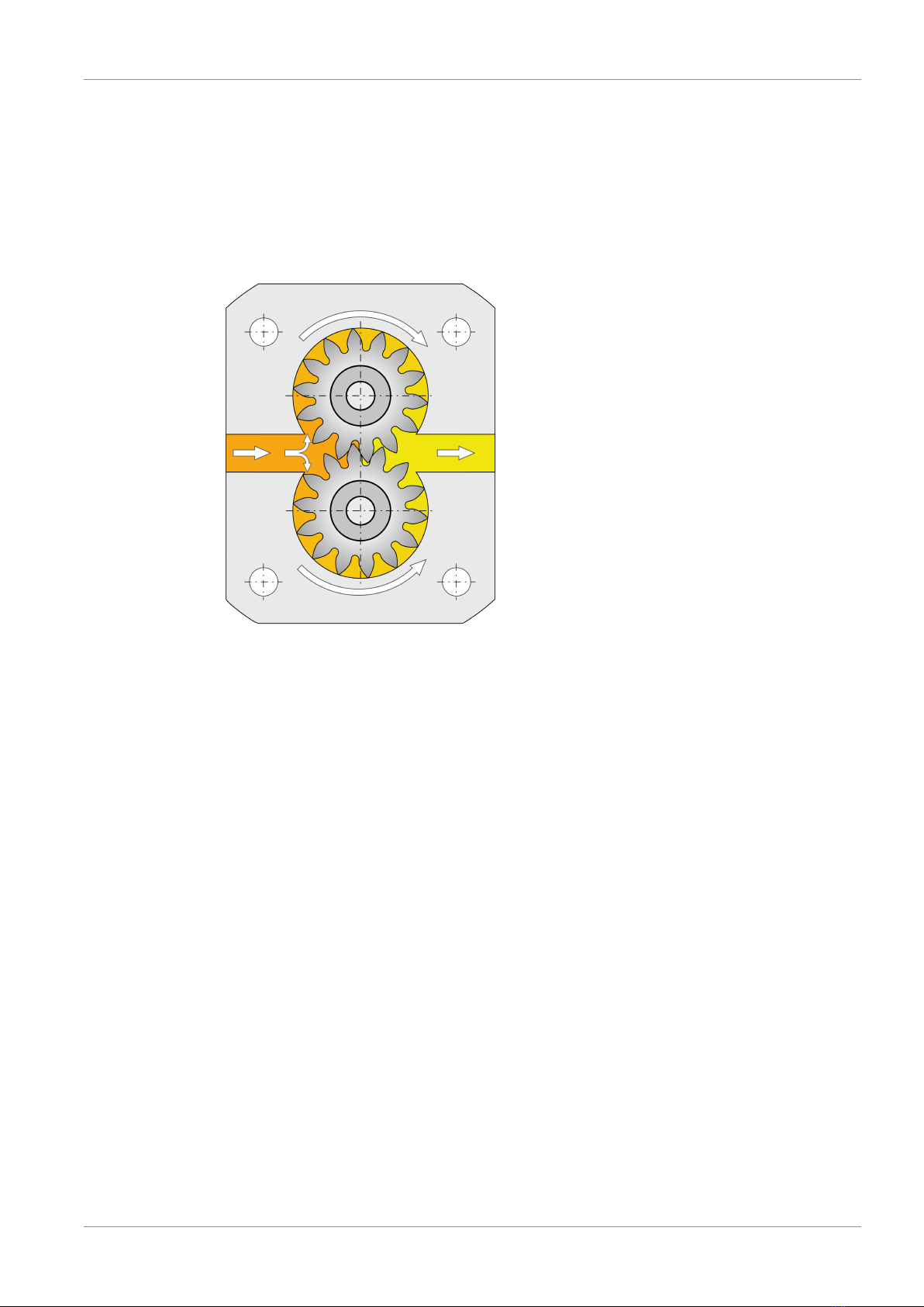
3.1 Functional principle .................................................................................................................................................................... 9
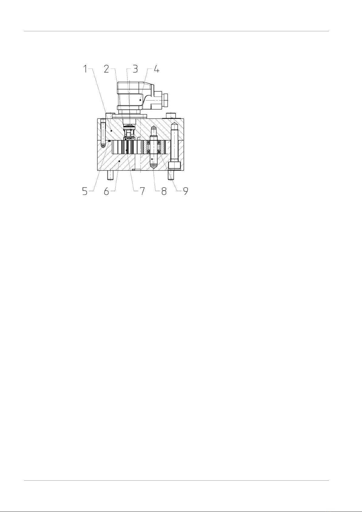
3.2 Basic design.................................................................................................................................................................................10
3.3 Type key ........................................................................................................................................................................................11
4 Technical data...................................................................................................................................................13
4.1 General ..........................................................................................................................................................................................13
4.2 Overview nominal sizes...........................................................................................................................................................14
4.3 Overview connection sizes.....................................................................................................................................................15
4.4 Flow resistance Δp ....................................................................................................................................................................17
4.4.1 Ball bearings..................................................................................................................................................................17
4.4.2 Plain bearings...............................................................................................................................................................20
4.5 Operating pressure...................................................................................................................................................................22
4.6 Permissible temperature range............................................................................................................................................23
4.7 Material data ...............................................................................................................................................................................24
4.8 Weight ...........................................................................................................................................................................................25
4.9 Dimensions ..................................................................................................................................................................................26
5 Transport and storage .....................................................................................................................................27
5.1 General ..........................................................................................................................................................................................27
5.2 Storage ..........................................................................................................................................................................................27
5.3 Storage conditions....................................................................................................................................................................28
6 Installation ........................................................................................................................................................29
6.1 Important notes about explosion protection.................................................................................................................29
6.2 Mechanical installation............................................................................................................................................................30
6.2.1 Preparation....................................................................................................................................................................30
6.2.2 Plate connection ........................................................................................................................................................30
6.2.3 Pipe connection...........................................................................................................................................................32
6.2.4 Rotary encoder ............................................................................................................................................................32
6.3 Electrical connection ................................................................................................................................................................33

Kracht GmbH
88046020002 iii
7 Operation start-up ...........................................................................................................................................34
7.1 Safety instructions for start-up ............................................................................................................................................34
7.2 Preparation...................................................................................................................................................................................34
7.3 PIN assignment ..........................................................................................................................................................................34
7.4 Signal lines ...................................................................................................................................................................................34
7.5 Further operation start-up.....................................................................................................................................................35
8 Removal.............................................................................................................................................................36
8.1 Safety instructions for removal ............................................................................................................................................36
8.2 Removal.........................................................................................................................................................................................37
9 Maintenance .....................................................................................................................................................38
9.1 Safety instructions for maintenance ..................................................................................................................................38
9.2 Maintenance work.....................................................................................................................................................................39
9.2.1 Cleaning - Desposits in the measuring device................................................................................................39
9.3 Maintenance instructions.......................................................................................................................................................40
9.4 Maintenance table ....................................................................................................................................................................41
9.4.1 Maintenance table......................................................................................................................................................41
9.4.2 Inspection: Discharge flow ......................................................................................................................................42
9.4.3 Inspection: Operating pressure.............................................................................................................................42
9.4.4 Inspection: Media temperature.............................................................................................................................42
9.4.5 Inspection: Condition of operating fluid ...........................................................................................................42
9.4.6 Audiometric monitoring: Unusual noise............................................................................................................42
9.4.7 Cleaning..........................................................................................................................................................................42
9.4.8 Visual inspection: Leakages ....................................................................................................................................42
9.4.9 Visual inspection: Measuring unit status...........................................................................................................42
9.4.10 Visual inspection: Condition of housing parts.................................................................................................43
9.4.11 Visual inspection: Bearing status ..........................................................................................................................43
9.4.12 Replace: Other seals...................................................................................................................................................43
9.4.13 Cleaning Desposits in the measuring device...................................................................................................43
10 Repairs...............................................................................................................................................................44
10.1 Safety instructions for repair.................................................................................................................................................44
10.2 General ..........................................................................................................................................................................................45
10.3 Detecting and eliminating failures......................................................................................................................................46

1 | General Kracht GmbH
4 / 46 88046020002
1 General
1.1 About the documentation
These operating instructions describe the installation and operation of the following device:
Gear type flow meter VC PULSE
These operating instructions are a component of the device and must be kept accessible for
the personnel near the device at all times.
The device is manufactured in different versions. Information about the version concerned in
the individual case can be found on the device's type plate.
If you have any questions about these operating instructions, please contact the manufac-
turer.
1.2 Manufacturer address
KRACHT GmbH
Gewerbestraße 20
DE 58791 Werdohl
Tel: +49 2392 935-0
Fax: +49 2392 935-209
Email: [email protected]
Web: www.kracht.eu
1.3 Applicable documents
In addition to these instructions, also observe the corresponding instructions for the existing
or planned systems or system parts.

Kracht GmbH General | 1
88046020002 5 / 46
1.4 Symbols
DANGER
Identification of an immediate hazard, which would result in death or severe bodily injury if
not avoided.
WARNING
Identification of a potential medium risk hazard, which would lead to death or severe bodily
injury if not avoided.
CAUTION
Identification of a low risk hazard, which could lead to minor or medium bodily injury if not
avoided.
ATTENTION
Flagging of notices to prevent property damage.
NOTICE
Identification of basic safety instructions.
Non-compliance can lead to hazards for people and the device.
TIPP
Flagging of special user tips and other especially useful or important information.

2 | Safety Kracht GmbH
6 / 46 88046020002
2 Safety
2.1 Intended use
1. The device has been designed for operation with fluid.
Dry operation is not permitted.
2. The product may only be operated when completely filled.
3. The fluid must be compatible with the materials used in the product. Chemical expertise
is required for that. Be careful with ethylene oxide or other catalytically or exothermically
reacting or self-decomposing substances. Please consult the manufacturer in cases of
doubt.
4. The product may only be used in normal industrial atmospheres.
If there are any aggressive substances in the air, always consult the manufacturer.
5. The product may only be operated in compliance with these operating instructions and
the applicable documents.
Deviating operating conditions require the express approval of the manufacturer.
6. Use of the product for purposes other than those for which it is intended invalidates any
warranty.
2.2 Personnel qualification and training
The personnel designated to assemble, operate and service the device must be properly
qualified.
This can be through training or specific instruction.
Personnel must be familiar with the contents of this operating instructions.
NOTICE
Read the operating instructions thoroughly before use.

Kracht GmbH Safety | 2
88046020002 7 / 46
2.3 Basic safety instructions
NOTICE
Basic safety instructions
Non-compliance can lead to hazards for people and the unit.
a) Follow existing regulations for accident prevention and safety at work as well as the in-
ternal regulations of the operating company.
b) Ensure the greatest possible cleanliness.
c) Wear suitable personal protective equipment.
d) Do not remove type plates or other information or make them illegible or unrecognis-
able.
e) Do not make any technical modifications.
f) Comply with maintenance intervals.
g) Only use spare parts approved by the manufacturer.
2.4 Fundamental hazards
DANGER
Hazardous fluids
Danger to life when handling hazardous fluids.
a) Comply with the safety data sheets and regulations on handling the hazardous fluids.
b) Collect and dispose of hazardous fluids so that no hazard is created for persons or the
environment.
DANGER
Rotating parts!
Danger of death due to body parts, hair or clothing getting trapped or entangled.
a) Before all work, ensure that existing drives are voltage-free and pressure-free.
b) Securely prevent restarting during all work.
DANGER
Exposed electrical components
Risk of fatal electric shock.
a) Adhere to the special safety regulations for all work on electrical systems.
Switch off electrical systems and secure them against being switched on again.
b) Work on electrical systems may only be carried out by a qualified electrician.
c) Use only connection lines that are resistant to ambient influences and media.

2 | Safety Kracht GmbH
8 / 46 88046020002
WARNING
Failure of pressure bearing parts due to overload
Risk of injury from flying parts.
Risk of injury due to splashing fluids.
a) Depressurize the system before all work.
b) Securely prevent the pressure from being restored during work.
WARNING
Failure of pressure bearing parts due to overload
Risk of injury from flying parts.
Risk of injury due to fluid spurting out.
a) Use only connections and lines approved for the expected pressure range.
b) Securely prevent the permissible pressures from being exceeded, e.g. by using pressure
relief valves or bursting discs.
c) Pipelines must be designed in such a way that no tension e.g. caused by changes in
length due to fluctuations in temperature can be transferred to the product.

Kracht GmbH Device description | 3
88046020002 9 / 46
3 Device description
3.1 Functional principle
The measuring unit is driven by the flow of fluid based on the principle of a gear motor.
The gears run in a contactless manner in the measuring chamber. The lowfriction bearings or
plain bearings act as the bearing elements.
The gear movement is sampled in a contactless manner through the sensors installed in the
cover. There is a pressure-resistant amagnetic division between the sensor space and meas-
uring chamber.
During the rotation of the measuring unit by one tooth pitch, a signal occurs per sensor that
corresponds to the so-called geometric tooth volume of Vgz. A value that is stated in tech-
nical documents as the nominal volume to specify the unit size.
The two-channel scanning facilitates a higher measuring resolution and detection of the dir-
ection of the flow rate.
In the gear type flow meter, the drive direction of the flow of fluid is independent of the dir-
ection.

3 | Device description Kracht GmbH
10 / 46 88046020002
3.2 Basic design
1 Cover 6 Housing
2 Magnet 7 Gears
3 A-magnetic divider 8 Bearing journal
4 Magnetic rotary encoder 9 Bearing
5 O-ring

Kracht GmbH Device description | 3
88046020002 11 / 46
3.3 Type key
Ordering example
VC 1 K 1 E 1 P 5 E 512
1. 2. 3. 4. 5. 6. 7. 8. 9. 10. 11.
Explanation of type key
1. Product name
2. Nominal size (Rated volume)
Vgz 0.025; 0.04; 0.1; 0.2; 0.4; 1; 3; 5; 12; 16
3. Bearing
KBall bearing CBall bearing (increased clearance )
HHybrid ball bearing GCarbide plain bearing
4 .Material
1Housing: EN-GJS-400-15 (GGG-40)
Gears: Steel 3Housing: EN-GJS-600 (GGG-60)
Gears: Steel
2Housing: Stainless steel
Gears: Stainless steel 4
Housing: Aluminium
Gears: Stainless steel (Nominal size
0.2)
5. Seal type
FFKM KFFKM
EEPDM QFVMQ
PFEP
6. Surface
1Standard (painted) 3Without
2Paint Skydrol resistant
7. Type of connection
PPlate structure RPipe connection
8. Sensor system
22 Sensors 42 Sensors protected against vibra-
tion and condensation
11 Sensor 5Encoder
3Without Sensor system
9. Version of the sensor system
SStandard KX ATEX High temperature PLUS
HHigh temperature RRed. supply voltage
KHigh temperature PLUS LIO-Link
TLow temperature VWithout Preamplifier
XATEX EEncoder
10. Cable length
Without Cable 5With 5 m Cable

3 | Device description Kracht GmbH
12 / 46 88046020002
Explanation of type key
2With 2 m Cable 10 With 10 m Cable
11. Electrical connection
HHirschmann plug (Standard) EAluminium terminal box (M12x1);
ext. electronics decoupeable
MHirschmann plug
(M12x1/-4pole) VWithout
KAluminium terminal box
(M12x1/-4pole) 512 Encoder 512 Imp/U
(M12x1/-4pole)
CAluminium terminal box
(Cannon plug) 2500 Encoder 2500 Imp/U
(M12x1/-4pole)

Kracht GmbH Technical data | 4
88046020002 13 / 46
4 Technical data
4.1 General
General information
Design Gear motor
Housing connection (1) Plate connection / Pipe connection
Mounting position Any
Flow direction Any
Viscosity ν depending on the product
Operating pressure
p
(perm. contin-
ous pressure) Operating pressure
pmax
(Pressure peaks)
Permissible pressure loss Δpmax
16 bar / 40 bar
(depending on the product)
Fluid temperature ϑm min.
Permissible temperature range [}23]
ϑm max.
Ambient temperature ϑu min.
ϑu max.
Material Material data [}24]
Permissible size of foreign particles in the
medium General [}14]
Linearized measuring accuracy
Permissible meda
Lubricating and poorly lubricating fluids in
the frame of the specified operating para-
meters
(Please consult the manufacturer in cases
of doubt.)
Abrasive components: General [}14]
(1) Overview connection sizes [}15]

4 | Technical data Kracht GmbH
14 / 46 88046020002
Linearized measur-
ing accuracy
[µm]
Ball bearing ± 0.3%
from 20 mm²/s
20
50 ( 224)
Ball bearing
(increased clearance)
± 0.5%
from 50 mm²/s 30
Hybrid ball bearing ± 1%
from 20 mm²/s 20
Carbide plain bearing ± 0.5%
from 100 mm²/s 30
Bronze plain bearings ± 1%
from 100 mm²/s 50
4.2 Overview nominal sizes
Nominal size Measuring range [l/min]
Bearing
Ball bearing Ball bearing
(increased
clearance)
Hybrid ball
bearing
Carbide plain
bearing
Bronze plain
bearings
0,025 0.008 - 2 - 0.008 - 2 0.02 - 2(1) -
0.04 0.02 - 4 - 0.02 - 4 - -
0.1 0.04 - 8 - 0.04 - 8 0.04 - 8 -
0.2 0.16 - 16 0.16 - 16 0.16 - 16 0,16 - 16 -
0.4 0.2 - 40 - - 0.2 - 30 -
10.4 - 80 0.4 - 80 0.4 - 80 0.3 - 60 0.6 - 40
30.6 - 160 0.6 - 160 - 0.6 - 100 -
5(2) 1 - 250 1 - 250 - 1 - 160 1.2 - 80
12 2 - 600 - - - -
16 3 - 700 - - - -
(1) Linearized measuring accuracy ± 3 %; Repeatability ± 1.5 %
(2) VC 5 …/224: Messbereich 1 – 160 [l/min]; Linearized measuring accuracy ± 0.5 % ab ≥ 50
mm²/s; Repeatability ± 0.05 %

Kracht GmbH Technical data | 4
88046020002 15 / 46
4.3 Overview connection sizes
Nominal size Special number Type of connection (1)
R
(Pipe connec-
tion)
P
(Plate structure)
With Connection
plate
Without Con-
nection plate
0.025 - G1/8
MVC .. R. B.
G3/8
See "Technical
data sheets"
MVC .. R. C.
G1/2
0.04 - G1/4
MVC .. R. B.
G3/8
MVC .. R. C.
G1/2
0.1 - G 3/8
MVC .. R. B.
G3/8
MVC .. R. C.
G1/2
0.2 - G 3/8
MVC .. R. B.
G3/8
MVC .. R. C.
G1/2
0.4 - G 1/2
MVC .. R. C.
G1/2
MVC .. R. D.
G3/4
1- G 1/2
MVC .. R. C.
G1/2
MVC .. R. D.
G3/4
MVC .. R. E.
G1
3- G 1
MVC .. R. E.
G1
MVC .. R. G.
G1 1/2
MVC .. V. E.
SAE 1“ – 6000 psi
5- G 1
MVC .. R. E.
G1
MVC .. R. G.

4 | Technical data Kracht GmbH
16 / 46 88046020002
Nominal size Special number Type of connection (1)
R
(Pipe connec-
tion)
P
(Plate structure)
With Connection
plate
Without Con-
nection plate
G 1 1/2
MVC .. V. E.
SAE 1“ – 6000 psi
MVC .. V. F.
SAE 1 1/4“ – 6000
psi
224 SAE 1“ – 3000
psi -
12 - -
MVC .. V. G.
SAE 1 1/2“ – 6000
psi
16 - -
MVC .. V. G.
SAE 1 1/2“ – 6000
psi
(1) Pipe thread: ISO 228-1; Flange connection: ISO 6162-1 (SAE J518)

Kracht GmbH Technical data | 4
88046020002 17 / 46
4.4 Flow resistance Δp
4.4.1 Ball bearings
VC 0.025
VC 0.04
VC 0.1

4 | Technical data Kracht GmbH
18 / 46 88046020002
VC 0.2
VC 0.4
VC 1

Kracht GmbH Technical data | 4
88046020002 19 / 46
VC 3
VC 5
VC 12
VC 16

4 | Technical data Kracht GmbH
20 / 46 88046020002
4.4.2 Plain bearings
VC 0.025
VC 0.1
Table of contents
Other Kracht Measuring Instrument manuals
Popular Measuring Instrument manuals by other brands

Omega Engineering
Omega Engineering DP-F30 Series Operator's manual

FLIR
FLIR EXTECH HDV-WTX1 Informational sheet

Druck
Druck DPI 705 Calibration instructions

Lumel
Lumel N27P User Manual & Quick Start

Endress+Hauser
Endress+Hauser Liquiline System CA80AM Brief operating instructions

Veratron
Veratron OceanLink operating instructions