Kramer FC-5 User manual

Kramer Electronics, Ltd.
USER MANUAL
Model:
FC-5
Protocol Translator

Contents
i
Contents
1
Introduction 1
2
Getting Started 1
3
Overview 2
3.1
Quick Start 3
4
Your FC-5 Protocol Translator 4
5
Configuring the Kramer FC-5 Manager Software 6
5.1
Installing and Running the Kramer FC-5 Manager Software 6
5.2
Using the Translation List Window 7
5.2.1
Entering Data in the New Command Window 8
5.2.2
Editing Data in the Command Window 9
5.2.3
Erasing a Command from the Command Translation List Window 10
5.3
Connecting a PC (CONFIG Port) 11
5.4
Dipswitch Settings 11
5.5
Assigning the Translation List Driver Commands 12
6
Using the FC-5 13
6.1
Transmitting Commands via a PC or Remote Controller 13
6.2
Transmitting Commands via the Dry Contacts 13
6.3
Transmitting Commands via the Relays 14
6.4
Transmitting Commands via the Dry Contacts and Relays 15
7
Upgrading Firmware 16
7.1
Downloading from the Internet 16
7.2
Connecting the PC to the RS-232 CONFIG Port 16
7.3
Upgrading Firmware 17
8
Technical Specifications 18
Figures
Figure 1: FC-5 Protocol Translator 4
Figure 2: FC-5 (Top Side Panel) 4
Figure 3: FC-5 (Lower Side Panel) 4
Figure 4: FC-5 Underside 5
Figure 5: Port Selection Window 6
Figure 6: Translation List Window 7
Figure 7: New / Open File Menu Command Dialog Box 8
Figure 8: New Command Window 8
Figure 9: Edit Command Window 9
Figure 10: Remove Command Prompt 10
Figure 11: Connecting a PC 11
Figure 12: Connecting a PC without using a Null-modem Adapter 11
Figure 13: The JTG Sender Window 17

KRAMER: SIMPLE CREATIVE TECHNOLOGY
Contents
ii
Tables
Table 1: FC-5 Protocol Translator Features 5
Table 2: Underside Features 5
Table 3: Translation List Window Functionality 7
Table 4: New Command Window Functionality 9
Table 5: Edit Command Window Functionality 10
Table 6: Dipswitch Definitions 11
Table 7: Dipswitch Settings 11
Table 8: Technical Specifications of the FC-5 Protocol Translator 18

Introduction
1
1 Introduction
Welcome to Kramer Electronics (since 1981): a world of unique, creative and
affordable solutions to the infinite range of problems that confront the video,
audio and presentation professional on a daily basis. In recent years, we have
redesigned and upgraded most of our line, making the best even better! Our
500-plus different models now appear in 8 Groups
1
, which are clearly defined
by function. Congratulations on purchasing your Kramer TOOLS: FC-5
Protocol Translator, which is ideal for:
Operating switchers with different RS-232 protocols
Controlling screens, projectors, lights, security gates via the relays
Using contact closure switches to operate RS-232 controlled equipment
The package includes the following items:
FC-5
CD-ROM Kramer FC-5 Manager Driver Translation software with two
sample files
Power adapter (12V DC Input)
This user manual
2
2 Getting Started
We recommend that you:
Unpack the equipment carefully and save the original box and packaging
materials for possible future shipment
Review the contents of this user manual
Use Kramer high performance high resolution cables
3
1 GROUP 1: Distribution Amplifiers; GROUP 2: Video and Audio Switchers, Matrix Switchers and Controllers; GROUP 3:
Video, Audio, VGA/XGA Processors; GROUP 4: Interfaces and Sync Processors; GROUP 5: Twisted Pair Interfaces;
GROUP 6: Accessories and Rack Adapters; GROUP 7: Scan Converters and Scalers; and GROUP 8: Cables and Connectors
2 Download up-to-date Kramer user manuals from the Internet at this URL: http://www.kramerelectronics.com
3 The complete list of Kramer cables is on our Web site at http://www.kramerelectronics.com

KRAMER: SIMPLE CREATIVE TECHNOLOGY
Overview
2
3 Overview
The unique FC-5 is a high quality TOOL designed to make an RS-232
controlled machine (Kramer and non-Kramer) compatible with other RS-232
based protocols
1
.
In particular, the FC-5:
By default, comes configured with two translation drivers: a Generic
Switcher Protocol to Kramer’s “Protocol 2000”; and the Sierra Video Systems
(SVS) Protocol to Kramer’s “Protocol 2000”
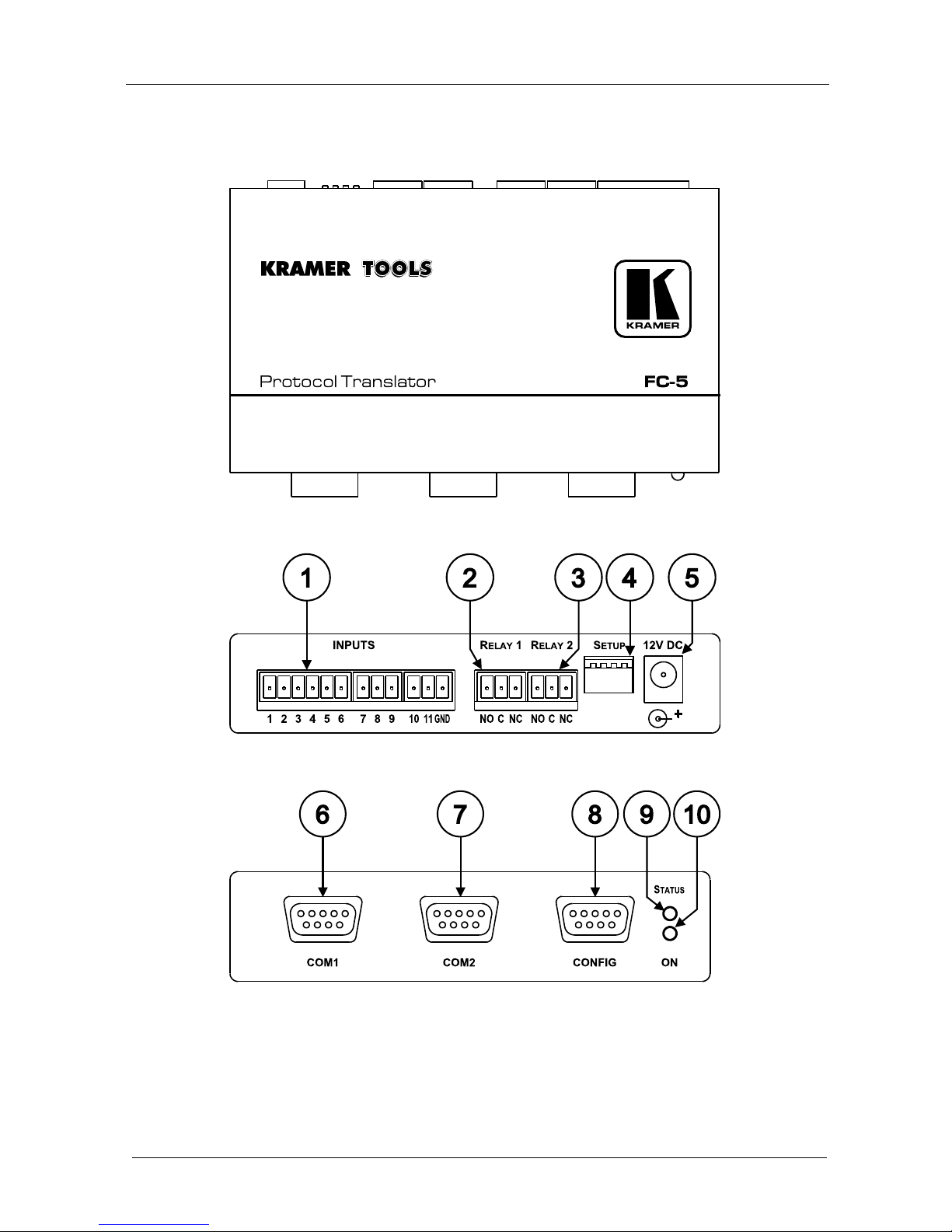
Can also be used as a programmable controller. It features two relays for
the simplified and centralized control of room functions (such as lighting,
closing blinds, and so on). The two output relays have normally open (NO)
and normally closed (NC) contacts
Features connections for up to eleven remote contact closure switches (to
trigger RS-232 commands and / or control the relays)
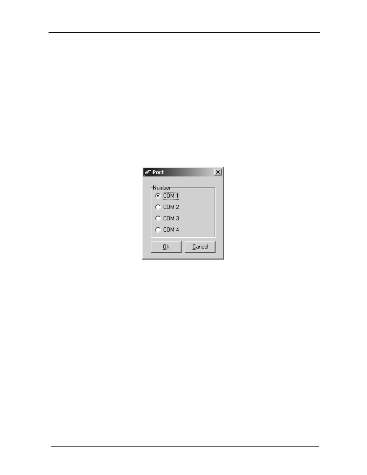
Includes an easy-to-use PC application program that lets you build
translation tables for the FC-5 to define the association between codes for the
COM ports, relays and contact closures. The FC-5 can be configured to work
with up to four translation tables, and each one can include up to 256
translation commands. Dipswitches are used to select between the translation
tables
Supports firmware upgrade
Is housed in a Kramer TOOLS enclosure and is 12VDC fed
Achieving the best performance means:
Connecting only good quality connection cables, thus avoiding
interference, deterioration in signal quality due to poor matching, and elevated
noise levels (often associated with low quality cables)
Avoiding interference from neighboring electrical appliances and
positioning your FC-5 away from moisture, excessive sunlight and dust
Caution – No operator-serviceable parts inside unit.
Warning – Use only the Kramer Electronics input power
wall adapter that is provided with this unit
2
.
Warning – Disconnect power and unplug unit from wall
before installing or removing device or servicing unit.
1 Data is transferred at 9600 baud with No parity, 8 data bits and 1 stop bit
2 For example: model number AD2512C, part number 2535-000251

Overview
3
3.1 Quick Start
This Quick start chart summarizes the basic steps when connecting a FC-5:

KRAMER: SIMPLE CREATIVE TECHNOLOGY
Your FC-5 Protocol Translator
4
4 Your FC-5 Protocol Translator
Figure 1, Figure 2, Figure 3 and Table 1 define the FC-5:
Figure 1: FC-5 Protocol Translator
Figure 2: FC-5 (Top Side Panel)
Figure 3: FC-5 (Lower Side Panel)

Your FC-5 Protocol Translator
5
Table 1: FC-5 Protocol Translator Features
# Feature Function
1 INPUTS Contact Closure
Remote Control PINs
Connects to a dry contact switch (see section 5.5)
2 RELAY 1 Terminal Block
3 RELAY 2 Terminal Block
Connect to up to room items (such as lighting, screen settings, blinds, and
so on). The PINOUT is: NO: Normally Open; C: Common Voltage; NC:
Normally Closed
4 SETUP Dipswitches Used to select translation drivers (see section 5.4)
5 12V DC +12V DC connector for powering the unit
6 COM1 DB9 RS-232 port Connects to the Kramer or other device
7 COM2 DB9 RS-232 port Connects to the Kramer or other device
8 CONFIG DB9 port Connects to the RS-232 port on a PC
9 STATUS LED Blinks when transmitting commands
10 ON LED Illuminates when receiving power
Figure 4
1
and Table 2 define the underside switches, which are designed to be
used for firmware upgrade only. An adhesive label
2
protects access to them.
The label should only be removed when upgrading to new firmware (see
section 7).
Table 2: Underside
Features
# Feature Function
1 Switch
2 Switch
3 Switch
Slide all 3
switches down
to set to OFF
(Normal mode)
3
.
Slide all 3
switches up to
set to ON
(Program mode)
Figure 4: FC-5 Underside
1 Shows the underside with the adhesive label removed
2 Marked “For Programming only! Do not remove, see user manual”
3 The default

KRAMER: SIMPLE CREATIVE TECHNOLOGY
Configuring the Kramer FC-5 Manager Software
6
5 Configuring the Kramer FC-5 Manager Software
This section describes how to:
Install and run the Kramer FC-5 Manager software, see section 5.1
Use the Translation List window, see section 5.2
Connect and assign the list translation driver commands, see sections 5.3,
5.4, and 5.5
5.1 Installing and Running the Kramer FC-5 Manager Software
To install the FC-5 Manager software:
1. Insert the CD-ROM in the CD-ROM drive, double click the FC5Manager icon.
The Port selection window appears:
Figure 5: Port Selection Window
2. Choose the appropriate COM port for configuration via the serial cable and
click OK.
The Translation List window (see Figure 6) opens.

Configuring the Kramer FC-5 Manager Software
7
5.2 Using the Translation List Window
Figure 6 and Table 3 define the Translation List window. Double clicking
COMMAND(1) opens the Edit command window (see section 5.2.2).
Figure 6: Translation List Window
Table 3: Translation List Window Functionality
Feature Function
New Creates a new blank file
Open Opens or finds a Protocol file (see Figure 7)
Save Saves the changed command list to the current translation driver file
Save As
Saves the current file with a different file name or location
File menu
commands
Exits Closes the application
Restart Not in use
COM Port Displays the Port Selection window (see Figure 5)
New Button Displays the New Command window (see Figure 8)
Edit Button Displays the Edit Command window (see Figure 9)
Remove Button
Displays the Remove Command prompt (see Figure 10)
Close Button Closes the Command Translation List window
Assign Button
1
Transmits the complete set to the COM ports of the FC-5 unit
1 The data is assigned to the “translation set” according to the DIP-switch setting at the time that the Assign button is pressed

KRAMER: SIMPLE CREATIVE TECHNOLOGY
Configuring the Kramer FC-5 Manager Software
8
Figure 7: New / Open File Menu Command Dialog Box
5.2.1 Entering Data in the New Command Window
Figure 8 and Table 4 define the New Command window:
Figure 8: New Command Window

Configuring the Kramer FC-5 Manager Software
9
Table 4: New Command Window Functionality
Feature Function
Properties NAME Field Defines the new command NAME
Automatically generates the text: COMMAND (x) where x is the next number in the
sequence. Lets you type over alternative text of up to 17 characters or leave the
field blank
Properties EVENT Field Defines the new EVENT. The drop-down list box offers a choice of:
COM1 RECEIVE, COM2 RECEIVE, DRYCONTACT_01 to DRYCONTACT_11
Properties ACTION Field Defines the new ACTION. The drop-down list box offers a choice of:
COM1 TRANSMIT, COM2 TRANSMIT, RELAY_01 ON, RELAY_02 ON,
RELAY_01 OFF, RELAY_02 OFF
Clear Button Removes the data that is entered in all the text boxes
Add Button Adds all the data that is entered in the text boxes to that new command
Close Button Closes the New Command window
5.2.2 Editing Data in the Command Window
Figure 9 and Table 5 define the Edit Command window:
Figure 9: Edit Command Window

KRAMER: SIMPLE CREATIVE TECHNOLOGY
Configuring the Kramer FC-5 Manager Software
10
Table 5: Edit Command Window Functionality
Feature Function
Properties
NAME Field
Defines the command NAME
Lets you type over alternative text of up to 17 characters or leave the field blank
Properties
EVENT Field
Defines the new EVENT. Lets you change the selection via the drop-down list box:
COM1 RECEIVE, COM2 RECEIVE, DRYCONTACT_01 to DRYCONTACT_11
Properties
ACTION Field
Defines the new ACTION. Lets you change the selection via the drop-down list box:
COM1 TRANSMIT, COM2 TRANSMIT, RELAY_01 ON, RELAY_02 ON, RELAY_01
OFF, RELAY_02 OFF
Clear Button Removes the data that is entered in all the text boxes
Apply Button Saves any changes made
1
OK Button Saves any changes made and closes the Edit Command window
Close Button Closes the New Command window
5.2.3 Erasing a Command from the Command Translation List Window
To erase a command from the Command Translation List window, select the
relevant command and then click Remove. Click Yes to the Remove prompt
message (see Figure 10):
Figure 10: Remove Command Prompt
1 Lets you continue to make changes in the Edit Command window

Configuring the Kramer FC-5 Manager Software
11
5.3 Connecting a PC (CONFIG Port)
Figure 11 and Figure 12 describe how to connect the CONFIG port.
Figure 11: Connecting a PC
To connect a PC to the FC-5, using the Null-modem adapter
provided with the machine (recommended):
Connect the RS-232 DB9 CONFIG rear panel port on the FC-5
unit to the Null-modem adapter and connect the Null-modem
adapter with a 9 wire flat cable to the RS-232 DB9 port on your PC
To connect a PC to the FC-5, without using a Null-modem adapter:
Connect the RS-232 DB9 port on your PC to the CONFIG
RS-232 DB9 rear panel port on the FC-5 unit, as Figure 12
illustrates
Figure 12: Connecting a PC without using a Null-
modem Adapter
5.4 Dipswitch Settings
Table 6 and Table 7 define the dipswitches, which are used to select the
translation drivers
1
.
Table 6: Dipswitch Definitions
DIPs
Set as follows:
1, 2 Determines the settings of the translation set
3, 4 Reserved
Table 7: Dipswitch Settings
Translation Set 1
Translation Set 2 Translation Set 3
Translation Set 4
Generic to
Kramer 2000
2
Sierra Video Systems
to Kramer 2000
2
1 OFF ON OFF ON
2 OFF OFF ON ON
1 For translating and for assigning
2 The default

KRAMER: SIMPLE CREATIVE TECHNOLOGY
Configuring the Kramer FC-5 Manager Software
12
5.5 Assigning the Translation List Driver Commands
Assign the configured translation list commands driver to the FC-5 unit. The
list is configured to the Translation Set selected by the DIP-switches at the
time of the download. This process can take several minutes. During the
process the “Assign” button of the Kramer FC-5 Manager software
application will blink, and the STATUS LED of the FC-5 unit will also blink.
At the end of this process the following message will appear: “Assigned
Successfully!”.

Using the FC-5
13
6 Using the FC-5
You can use your FC-5 to transmit commands via the:
PC or Remote Controller, see section 6.1
Dry contacts, see section 6.2
Relays, see section 6.3
Dry contacts and relays, see section 6.4
6.1 Transmitting Commands via a PC or Remote Controller
You can use your FC-5 to transmit commands via a PC or remote controller:
A PC or Remote
Controller is connected
1
to
the COM 1 port and a
controlled unit is
connected to the COM 2
port. In this example, the
PC or Remote Controller
transmits user-defined
commands to the Kramer
switcher
2
6.2 Transmitting Commands via the Dry Contacts
You can use the FC-5 to transmit commands via the dry contacts (see also
section 6.4):
The INPUTS contact closure
remote control pins let you
temporarily route an input to the
output by momentarily attaching
an input to the GND (Ground)
pin
3
. In this example INPUT 3 is
routed to the output, by
temporarily attaching PIN 3 to
PIN GND, and a Kramer
switcher
2
is connected to the
COM 2 port
1 Connection to COM1 or COM2 has to be according to the configuration
2 Or any other Kramer or non-Kramer RS-232 controllable unit
3 Do not connect more than one PIN to the Ground PIN at the same time

KRAMER: SIMPLE CREATIVE TECHNOLOGY
Using the FC-5
14
6.3 Transmitting Commands via the Relays
You can use your FC-5 to transmit commands via the relays:
A PC or Remote Controller is connected to the
COM 1 port. Relay 1 is connected to the blinds, and
relay 2 is connected to the lighting system. On each
3-pole terminal block connector, connect either: C
to NO, or C to NC
RELAY
PINOUT
C Common
NO Normally Open (that is, the electricity
is switched ON)
NC Normally Closed (that is, the
electricity is switched OFF)

Using the FC-5
15
6.4 Transmitting Commands via the Dry Contacts and Relays
You can use your FC-5 to transmit commands via the dry contacts to the
relays, and to a projector via RS-232:
The INPUTS contact
closure remote control
pins let you switch
commands to the
relays, and via
RS-232.
Relay 1 is connected to
the blinds, and relay 2
is connected to the
lighting system (see
section 6.3 for the
Relay PINOUT).
INPUT contact closure
remote control pins 1 to
4 are connected to
switches 1 to 4,
respectively.
In this particular
example, pressing:
Switch button 1
turns on the
projector
Switch button 2
turns off the
projector
Switch button 3
toggles the blinds
up/down
Switch button 4
toggles the lights
on/off

KRAMER: SIMPLE CREATIVE TECHNOLOGY
Upgrading Firmware
16
7 Upgrading Firmware
The FC-5 firmware is located in FLASH memory, which lets you upgrade to
the latest Kramer firmware version in minutes! The process involves:
Downloading from the Internet (see section 7.1)
Connecting the PC to the RS-232 CONFIG port (see section 7.2)
Upgrading Firmware (see section 7.3)
7.1 Downloading from the Internet
You can download the up-to-date file
1
from the Internet. To do so:
1. Go to our Web site at http://www.kramerelectronics.com and download
the file: “JTG_FC-5.zip” from the Technical Support section.
2. Extract the file: “JTG_FC-5.zip” to a folder (for example, C:\Program
Files\Kramer Flash).
3. Install the JTG-Sender application.
7.2 Connecting the PC to the RS-232 CONFIG Port
Before installing the latest Kramer firmware version on an FC-5 unit, do the
following:
1. On the underside (see Figure 4), slide all three switches to ON (Program
Mode), using a screwdriver.
2. Connect the 12V DC power adapter to the power socket and connect the
adapter to the mains electricity.
3. Open the JTG-Sender application (see section 7.1).
4. Connect the RS-232 DB9 CONFIG port to the Null-modem adapter and
connect the Null-modem adapter with a 9-wire flat cable to the RS-232
DB9 COM port on your PC (see Figure 12).
5. Follow the steps outlined in section 7.3.
1 The files indicated in this section are given as an example only. The actual file names can be modified

Upgrading Firmware
17
7.3 Upgrading Firmware
Follow these steps to upgrade the firmware:
1. Double click the JTG-Sender desktop icon.
The JTG-Sender window appears (see Figure 13).
Figure 13: The JTG Sender Window
2. Select the required COM Port
1
.
3. Press the File button to select the .jtg firmware file included in the
package.
4. Click the Send button to download the file. The Send button lights green.
5. Wait until downloading is completed and the green Send button turns off.
6. Disconnect the 12V DC power.
7. On the underside (see Figure 4), slide all three switches to OFF (Normal
Mode), using a screwdriver.
8. Connect the 12V DC power adapter to the power socket and connect the
adapter to the mains electricity.
The FC-5 now functions with the upgraded firmware.
1 To which the Remote Control is connected on your PC
Other manuals for FC-5
1
Table of contents
Popular Electronic Dictionary manuals by other brands

Canon
Canon Electronic Dictionary quick reference

Sennetech
Sennetech SCT-CRX-Pelco-Pelco quick start guide

LEXIBOOK
LEXIBOOK COLLINS POCKET ENGLISH SPELLCHECKER WITH... instruction manual

Resolution
Resolution Wireless Translator RE224DT manual

Ectaco
Ectaco Partner X8 quick start

LEXIBOOK
LEXIBOOK DC510I1 DICTEE KID MASTER LISTEN AND SPELL... manual