2
We would like to congratulate you on your new sweeper KRÄNZLE 1+1.
To ease your introduction to the use of the sweeper, we have provided the
following pages of explanations, tips and hints, which we ask you to read before
using for the first time.
It is our desire that the good characteristics of the KRÄNZLE 1+1 should justify
the confidence you demonstrated to us by making this purchase.
We tried to supply you with an efficient and dependable machine. Prior to
starting-up this machine, read the operating manual carefully. It will inform you in
detail about operation of the unit and provides valuable advice for service and
maintenance.
The KRÄNZLE 1+1 is designed
exclusively for sweeping floors, e.g. in
production facilities, warehouses,
parking sites, and pedestrian areas, for
collecting both, dry an moist matter.
Use in excess of these specifications
will be deemed to be improper use; the
manufacturer cannot be held liable for
consequential damage.
Proper use also includes that
maintenance work is done as specified
by the manufacturer.
As soon as the machine arrives,
please check whether any damage has
occured in transit.
This will be refunded to you if you
have confirmed the damage im-
mediately by the Forwarding agent.
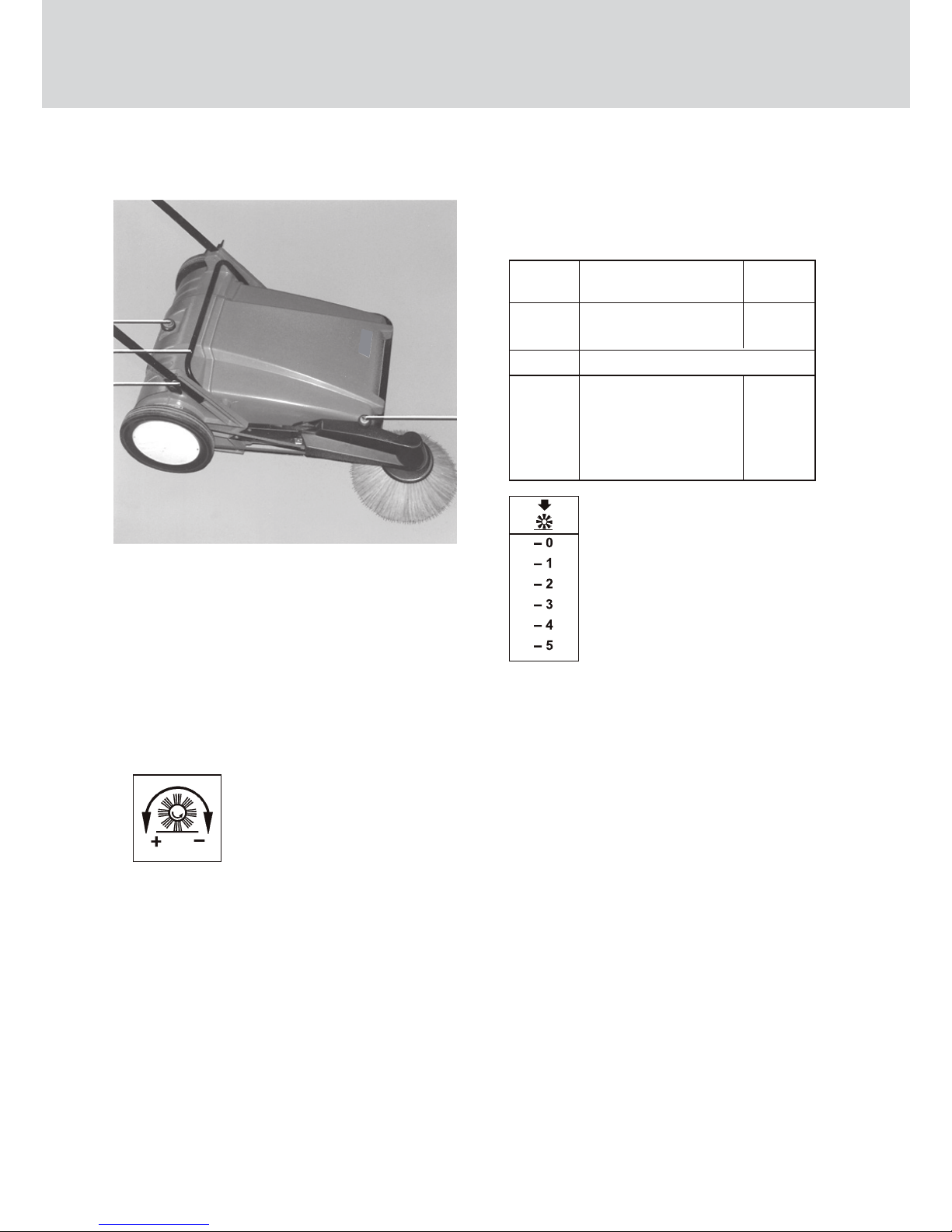
The sweeper ist adjusted for use
on even ground.
Dear customer
Description
Provisions for use............................14
Acceptance for the machine.............14
First operation...............................16
Assembly.........................................16
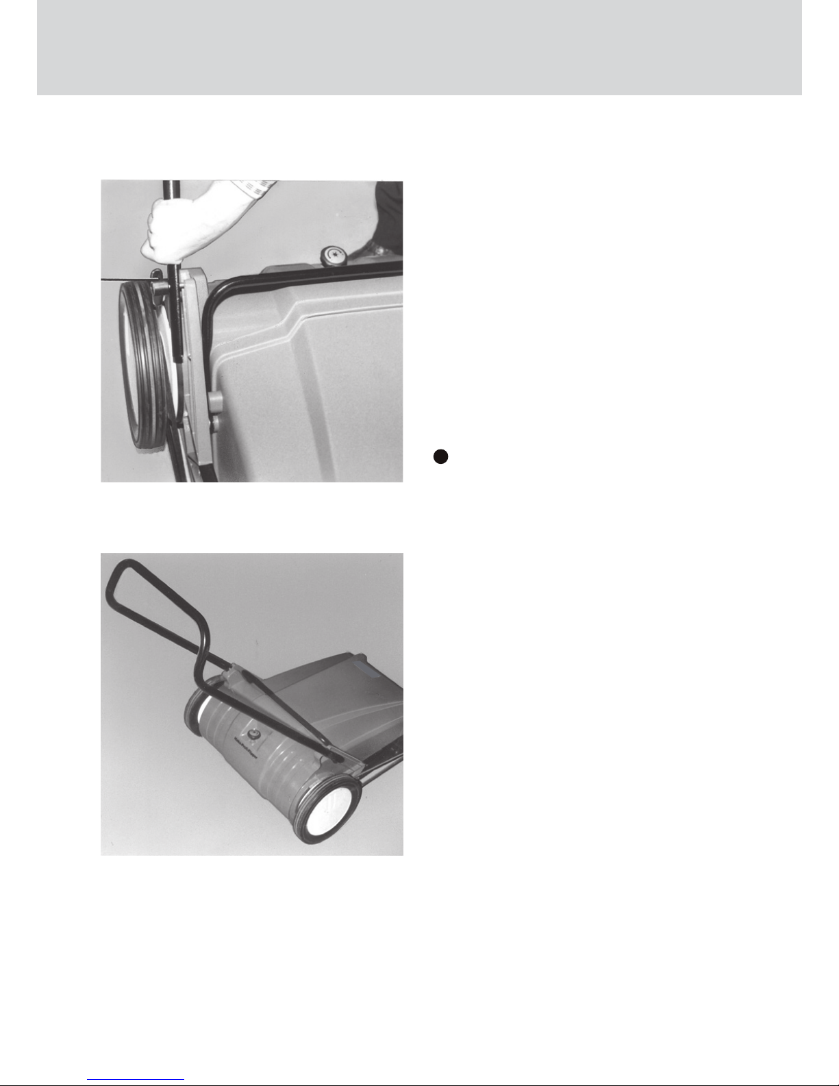
Attach handlebar.............................16
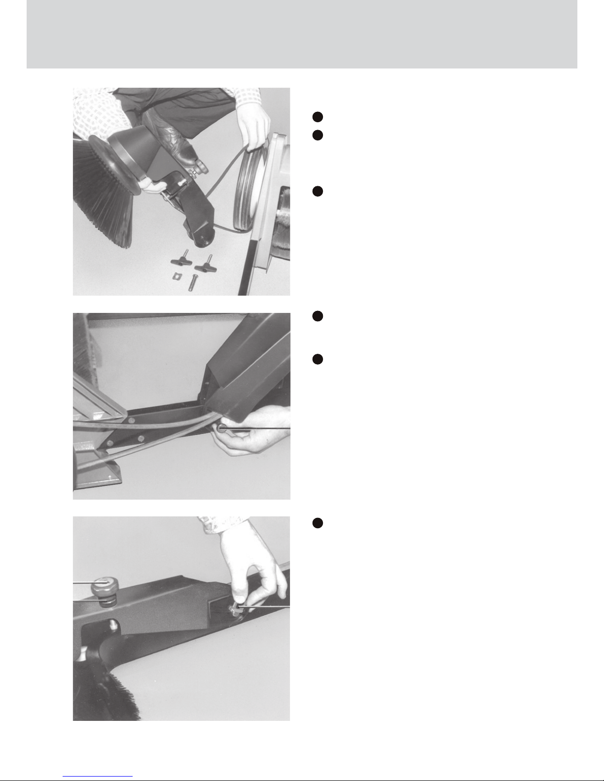
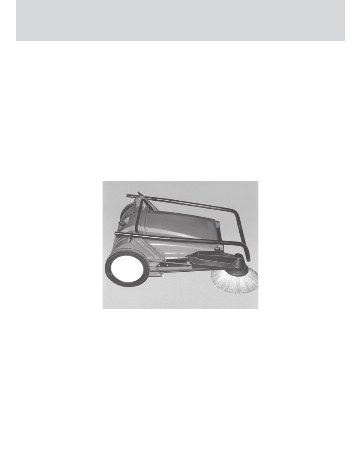
Attach side broom............................17
Operating the KRÄNZLE 1+1.......18
Controls...........................................19
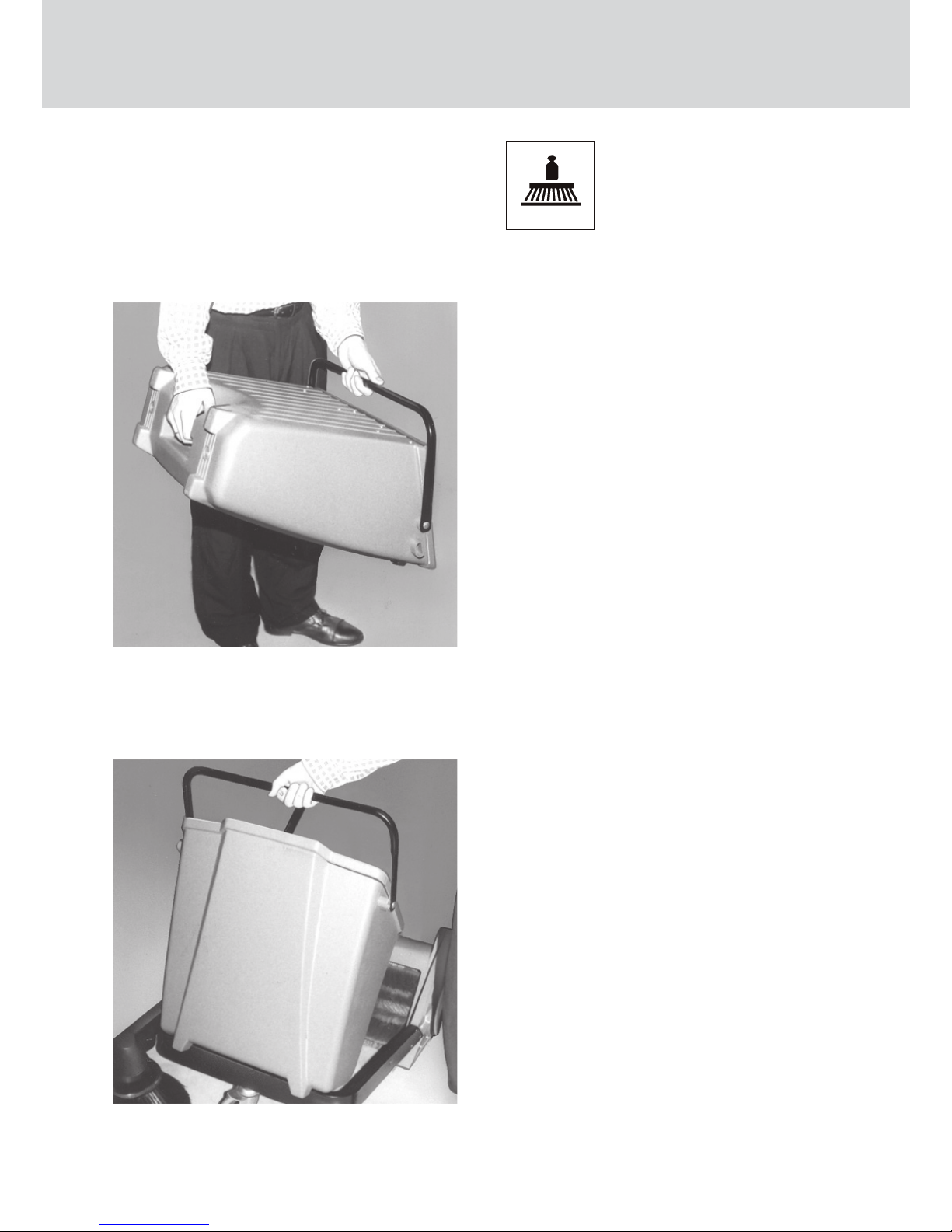
Emptying the dirt hopper..................20
Technical Data...............................15
Insert the dirt hopper........................20
Replacement of main broom............21
Side broom......................................22
Replacement of side broom.............22
Adjust tension of side broom
Vee belt...........................................22
Replacement of side broom
Vee belt...........................................23
Sealing lips......................................23
Greaser track wheels.......................24
Maintenance / Guarantee..............25
Maintenance works.........................25
Intervals..........................................25
Guarantee......................................25
width w/o side broom
width with side broom
height with handlebar, handlebar high position
height with handlebar, handlebar low position
height with folded handlebar
lenght with folded handlebar with side broom
lenght w/o side broom, handlebar high position
lenght w/o side broom, handlebar low position
lenght with side broom, handlebar high position
lenght with side broom, handlebar low position
weight (operating, incl. side broom)
drive wheels (dia./width)
swept width w/o side broom
swept width with side broom
broom roller dia.
broom roller width
min. dia. of roller broom
broom speed at 4 km/h (2.5 mph)
side broom (Polyester), dia.
side broom speed at 4 km/h (2.5 mph)
side broom drive (Vee belt)
dirt hopper (40 litres capacity)
surfacing rating (theoretic) at 4 km/h with side broom
720 (28.35)
790 (31.10)
1060 (41.7)
900 (35.4)
390 (15.35)
1,030 (40.5)
1,080 (42.5)
1,260 (49,6)
1,330 (52.4)
1,510 (59,4)
25 (55)
280 x 40
(11.02 x 1.57)
480 (18.9)
670 (26.38)
250 (9.84)
480 (18.9)
180 (7.09)
250
325 (12.8)
85
8 x 1765 5
25 - 28 usable
2,680
mm (”)
mm (”)
mm (”)
mm (”)
mm (”)
mm (”)
mm (”)
mm (”)
mm (”)
mm (”)
kg (lbs)
mm
(”)
mm (”)
mm (”)
mm (”)
mm (”)
mm (”)
rpm
mm (”)
rpm
mm
l2
m /h
Technical Data
Table of Contents
Description GB
15
_
+