KRATOS 68K-759HC User manual

12/10/2020 PK
SERVICE, INSTALLATION AND INSTRUCTION MANUAL
68K-759HC, 68K-773HC
69K-887HC, 69K-888HC
REACH-IN REFRIGERATOR
PLEASE READ CAREFULLY

Page 2 of 20
TABLE of CONTENTS
INTRODUCTION .......................................................................................................................................................................... 3
SERIAL NUMBER INFORMATION ............................................................................................................................................. 3
RECEIVING AND INSPECTING THE EQUIPMENT ................................................................................................................. 4
APPLIANCE SAFETY .................................................................................................................................................................... 4
IMPORTANT SAFEGUARDS ........................................................................................................................................................ 5
Electrical Connection ................................................................................................................................................................... 6
Refrigerant Disposal .................................................................................................................................................................... 6
Appliance Disposal ...................................................................................................................................................................... 6
APPLIANCE INSTALLATION ...................................................................................................................................................... 7
Remove Packaging Materials ....................................................................................................................................................... 7
Location Requirements ................................................................................................................................................................ 7
Inside cabinet: .............................................................................................................................................................................. 7
Outside cabinet: ............................................................................................................................................................................ 7
Installation Clearance ................................................................................................................................................................... 8
Leveling ....................................................................................................................................................................................... 8
Stabilizing .................................................................................................................................................................................... 8
Electrical Connection ................................................................................................................................................................... 8
OPERATION ................................................................................................................................................................................... 9
Refrigerated cycle ........................................................................................................................................................................ 9
Power Switch: .............................................................................................................................................................................. 9
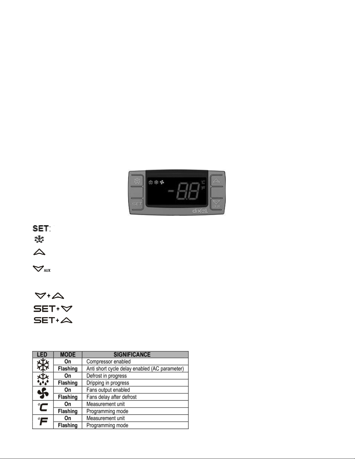
SOLID-STATE THERMOSTAT DE SC RI PT IO NS ......................................................................................................................... 9
1. FRONT PANEL COMMANDS. .............................................................................................................................................. 9
2. MAIN FUNCTIONS .............................................................................................................................................................. 10
3. ALARM SIGNALLING ........................................................................................................................................................ 10
TIPS FOR PROPER OPERATION, CLEANING AND MAINTENANCE ................................................................................. 11
CLEANING AND MAINTENANCE ........................................................................................................................................... 12
Exterior and Interior Cleaning of Appliances ............................................................................................................................ 12
Cleaning the Condenser Coil ..................................................................................................................................................... 12
Stainless Steel Care and Cleaning .............................................................................................................................................. 13
Gasket Maintenance ................................................................................................................................................................... 13
Doors/Hinges ............................................................................................................................................................................. 13
Drain Maintenance ..................................................................................................................................................................... 13
TROUBLESHOOTING GUIDE ................................................................................................................................................. 14
TROUBLESHOOTING CHART .................................................................................................................................................. 14
SERVICE AND TROUBLESHOOTING TIPS ............................................................................................................................. 15
DIMENSIONS AND TECHNICAL INFORMATION .................................................................................................................. 16
COMPONENT INFORMATION ................................................................................................................................................ 17
REFRIGERATION DIAGRAM .................................................................................................................................................... 17
WIRING DIAGRAMS .................................................................................................................................................................. 18
PARTS ............................................................................................................................................................................................ 19

Page 3 of 20
READ THIS MANUAL IN ITS ENTIRETY
TO HELP FAMILIARIZE YOURSELF WITH YOUR NEW EQUIPMENT BEFORE PROCEEDING.
We have provided many important safety messages in this manual.
Always read and obey all safety messages.
Understanding of safety messages will assist in alerting you to potential hazards, as well as tell you
how to reduce the chance of injury. Follow the instructions as outlined in this manual.
INTRODUCTION
This user’s manual is intended for installing, using and servicing your Argus appliance. It is recommended that this
manual be kept in an accessible place. Every Argus machine is designed and manufactured according to the highest
standards of safety and performance. It meets or exceeds UL 471 safety standards and sanitation standard NSF 7.
Argus assumes no liability or responsibility of any kind for products manufactured by Argus that have been altered in any
way, including the use of any parts and/or other components not specifically approved by Argus.
Argus reserves the right to make design changes and/or improvements at any time. Specifications and designs are
subject to change without notice.
SERIAL NUMBER INFORMATION
l The serial number of all self-contained freezers is located inside the unit on the left hand side near the top on the wall.
l Always have the serial number of your unit available when calling for parts or service.
Due to periodic changes in designs, methods, procedures, policies and regulations, the contents of this manual are subject
to change without notice. While we exercise good faith efforts to provide information that is accurate, we are not responsible
for errors or omissions in information provided or conclusions reached as a result of using this reference manual. By using
the information provided rather than simply using it for reference purposes, the user assumes all risks in connection with
such use.

Page 4 of 20
RECEIVING AND INSPECTING THE EQUIPMENT
Even though most equipment is shipped crated, care should be taken during unloading so the equipment is not damaged
while being moved into the building.
1. Visually inspect the exterior of the package and skid or container. Any damage should be noted and reported to the
delivering carrier immediately.
2. If the damage appears minor, open and inspect the contents with the carrier. Ta ke pho tog ra p hs of th e p ac k ag ing be for e i ts
opened. If the carrier is impatient & won’t wait, return the goods if the damage appears to be anything more substantial then
superficial harming of the external protective packing layers.
3. In the event that the exterior is not damaged, yet upon opening, there is concealed damage to the equipment, notify the
carrier. Notification should be made verbally as well as in written form.
4. Request an inspection by the shipping company of the damaged equipment. This should be done within 10 days from
receipt of the equipment.
5. Be certain to check the compressor compartment housing and visually inspect the refrigeration package. Be sure lines are
secure and base is still intact.
6. Freight carriers can supply the necessary damage forms upon request.
7. Retain all crating material until an inspection has been made or waived.
APPLIANCE SAFETY
Always read and obey all safety messages.
This is the Safety Alert Symbol. This symbol alerts you to potential hazards that can injure or kill you
and others. All safety messages will follow the Safety Alert Symbol and either the words
“DANGER”,
“WARNING” OR “CAUTION”.
DANGER
DANGER
means that failure to heed this safety statement may result in Death or Severe Personnel Injury.
WARNING
WARNING
means that failure to heed this safety statement may result in extensive product damage, serious
personal injury, or death.
CAUTION
CAUTION
means that failure to heed this safety statement may result in minor or moderate personal injury, or
property or equipment damage.
All safety messages will alert you to what the potential hazard is, tell you how to reduce the chance of injury, and let you
know what can happen if the instructions are not followed.
NOTE: IMPORTANT SAFETY INSTRUCTIONS
WARNING
To reduce the risk of fire, electric shock or injury, when using your appliance, follow these basic precautions:
l Plug into grounded 3-prong outlet.
l Do not remove grounding prong.
l Do not use an adapter.
l Do not use an extension cord.
l Disconnect power before cleaning.
l Disconnect power before servicing.
l Use 2 or more people to move and install appliance.
SAVE THESE INSTRUCTIONS

Page 5 of 20
IMPORTANT SAFEGUARDS
Before the
appliance
is used, it must be properly positioned and installed as described
in this manual, so read the manual carefully. We strongly recommend that you have a
professional install your new machine. The warranty may be affected or voided by
an incorrect installation. To reduce the risk of fire, electrical shock or injury when
using the
appliance
, follow basic precautions, including the following:
DANGER
• It is recommended that a separate circuit, serving only your appliance, be provided. Use receptacles that cannot
be turned off by a switch or pull chain.
• Please ensure that the required voltage is being supplied at all times.
• The unit should be plugged into a grounded and properly-sized electrical outlet with appropriate over-current
protection.
• Ensure unit is not resting on or against the electrical cord.
• Do not connect or disconnect the electric plug when your hands are wet.
• Never unplug the appliance by pulling on the power cord. Always grip the plug firmly and pull straight out from the
outlet.
• Never clean appliance parts with flammable fluids. Do not store or use gasoline or other flammable vapors and
liquids in the vicinity of this or any other appliance. The fumes can create a fire hazard or explosion.
• Before proceeding with cleaning and maintenance operations, make sure the power line of the unit is disconnected.
• Unplug the appliance or disconnect power before cleaning or servicing. Failure to do so can result in electrical
shock or death.
• If the unit is not in use for a long period of time, best to unplug the unit from the outlet.
• After unplugging or a power outage to the unit, wait at least 10 minutes before plugging it back in. Failure to do so
could cause damage to the compressor.
• Do not operate the appliance with a frayed or crimped power cord.
• Do not attempt to repair or replace any part of your appliance unless it is specifically recommended in this manual. A
qualified technician should do all other servicing or repairs.
WARNING
•
Use two or more people to move and install appliance. Failure to do so can result in back or other injury.
• This appliance must be properly installed and located in accordance with the Installation Instructions before it is used.
• Do not touch the cold surfaces in the appliance compartment when hands are damp or wet. Skin may stick to these
extremely cold surfaces.
• Setting temperature controls to the ZERO (0) position does not remove power from the appliance, it must be turned
off at the unit appliance circuit breaker or by unplugging it.
• To ensure proper ventilation for your appliance, choose a well-ventilated area with temperatures above 50ºF
(10ºC) and below 86ºF (30ºC). If in an environment with a temperature between 86 and 104ºF (30 to 40ºC) use of
a fan blowing into the utility compartment or similar auxiliary cooling of that area is required. This unit MUST be
installed in an area protected from the elements, such as wind, rain, water spray or drips.
• The appliance should not be located next to ovens, grills or other sources of high heat.
• It is important for the appliance to be level for proper operation. You may need to make adjustments to level it.
• Remove the packing materials & be sure to discard them as the work area is policed. Clean the appliance before using.
• Do not use this apparatus for other than its intended purpose.
• Only trained, qualified personnel should attend to & monitor the appliance’s performance and upkeep.
• Do not attempt to use the shelving as a ladder.

Page 6 of 20
IMPORTANT SAFEGUARDS (cont.)
Electrical Connection
Do not, under any circumstances, cut or remove the third (ground) prong from the power cord. For personal safety,
this appliance must be properly grounded. The power cord of this appliance is equipped with a 3-prong grounding
plug that mates with a standard 3-prong grounding wall outlet to minimize the possibility of electric shock hazard from
the appliance. Have the wall outlet and circuit checked by a qualified electrician to make sure the outlet is properly
grounded. The appliance should always be plugged into its own individual electrical outlet which has a voltage rating
that matches the rating label on the appliance. This provides the best performance and also prevents overloading
house wiring circuits which could cause a fire hazard from overheated wires. Repair or replace immediately all power
cords that have become frayed or otherwise damaged. Do not use a cord that has been crimped, shows cracks or has
frayed insulation abrasion damage along its length or at either end. When moving the appliance, be careful not to
damage the power cord.
Power Surges
Connecting the unit to the incorrect voltage or oversized circuit protection (i.e. a breaker rated for over 20 amps) is not
covered by the appliance warranty. Neither is a damaged power cord, using unauthorized electrical components and/or
modifying the units wiring.
It is recommended that the appliance circuit doesn’t incorporate either a GFI breaker or outlet.
Any complications created by use of a GFI are not covered by the unit’s warranty as they are prone to inadvertently tripping
off to often.
Refrigerant Disposal
If you are throwing away your old appliance it may have a cooling system that uses “Ozone Depleting” chemicals. Make
sure the refrigerant is removed for proper disposal by a qualified service technician.
Appliance Disposal
Follow and comply with all applicable codes and ordinances, cut the plug off the electrical power cord, remove the
door(s) and discard the shelving. This prevents misuse of the unit after its been scrapped.

Page 7 of 20
APPLIANCE INSTALLATION
Remove Packaging Materials
IMPORTANT:
Do not remove any permanent instruction labels or the data label on your appliance.
• Remove tape and glue from your appliance before using.
• To remove any remaining tape or glue, rub the area briskly with your thumb. Tape or glue residue can also be
easily removed by rubbing a small amount of liquid dish soap over the adhesive with your fingers. Wipe with
warm water and dry with a soft cloth.
• Do not use sharp instruments, rubbing alcohol, flammable fluids, or abrasive cleaners to remove tape or glue.
These products can damage the surface of your appliance.
NOTICE:
LOSS OR SPOILAGE OF PRODUCTS IN YOUR APPLIANCE IS NOT COVERED BY WARRANTY. IN ADDITION TO
FOLLOWING RECOMMENDED INSTALLATION PROCEDURES AFTER ITS BEEN SET IN PLACE, DON’T RUN THE
APPLIANCE 24 HOURS TO LET OIL IN THE REFRIGERANT LINE TO RE-EQUILIBRATE. (DON’T LOAD WITH
PRODUCT UNTIL THE UNIT TEMPERATURE HAS REACHED ITS SET POINT.)
Location Requirements
• Appliances represented in this manual are intended for indoor use only.
• Be sure the location chosen has a floor strong enough to support the total weight of the cabinet and contents as a
fully loaded unit can weigh as much as 1500 pounds.
• Reinforce the floor as necessary to provide for maximum loading.
• For the most efficient refrigeration, be sure to provide good air circulation inside and out.
Inside cabinet:
Do not pack the units so full that air cannot circulate. The refrigerated air is discharged at the top rear of the unit. It is
important to allow for proper air flow from the top rear to the bottom of the unit. Obstructions to this air flow can cause
evaporator coil freeze ups and loss of temperature or overflow of water from the evaporator drain pan. The shelves have
a rear turn up on them to prevent this. However, bags and other items can still be located to the far rear of the cabinet. Air
is brought into the evaporator coil with fans mounted to the front of the coil.
Outside cabinet:
Be sure that the unit has access to ample air. Avoid hot corners and locations near stoves and ovens.
It is recommended that the unit be installed no closer than 2" (51mm) from any wall, a max door swing clearance of 60.5
in. (1537mm) and with at least a 12" (305mm) of clear space above the unit. Adequate air flow (≤86º F) into the utility
compartment is needed to deliver proper performance and extend the appliance life.
WARNING
Excessive Weight Hazard
Use two or more persons to move and install appliances.
Failure to do so may result in back or other injury.

Page 8 of 20
APPLIANCE INSTALLATION (cont.)
Installation Clearance
Leveling
Ensure the floor where the unit is to be located is level. (It is ok to slope down from front to rear by up to 1/4” – it mustn’t
slope from the rear to the front.)
Stabilizing
All models are supplied with casters for your convenience. It is very important, however, that the cabinet be installed in a
stable condition with the front wheels locked while in use. Should it become necessary to lay the unit on its side or back for
any reason, allow at least 24 hours before start-up to allow compressor oil to flow back into place. Failure to meet this
requirement can cause compressor failure and unit damage which isn’t covered by the appliance warranty.
Reversing The Door (Single Door Models Only)
Single door models can be converted from right-hand hinged to left-hand hinged and vice-versa by removing the door
hinges from both the door and unit, reversing their locations and reattaching them, and re-hanging the door upside-down.
NOTICE:
Unit repairs will not be subject to standard unit warranties if due to improper installation procedures or
utilizing an unqualified installer technician to commission the unit.
Electrical Connection
Refer to the amperage data on the Technical Information table, the serial tag, your local code or the National Electrical Code
to be sure that unit is connected to the proper power source.
DANGER
The unit must be turned OFF and disconnected from the power source whenever performing
service, maintenance functions or cleaning the refrigerated area. Failure to comply may
result in Death or Severe Personnel Injury.
12” (305mm) clear space
2”
51mm
Single Door Models
Double Door Models
27 in
686 mm
27 in
686 mm
60.5 in
1537 mm
Max Door Swing
Clearance
60.5 in
1537 mm
Max Door Swing
Clearance

Page 9 of 20
OPERATION
Refrigerated cycle
Refrigerators: During the refrigeration cycle, the evaporator fans will run continuously even when one or more doors are
open. The door switch will activate the lights when opened on solid door models only. Glass door models lights are turned
on manually using a switch located next to the main power switch.
1.
Every 6 hours, the unit will turn off and to allow the evaporator coil to air defrost. The controller now displays defrost
symbol. When the coil temperature reaches 53°F (12°C) or after 30 minutes of defrost, the unit will turn on again.
2.
Anti-condensation heaters on door frames work in conjunction with the compressor.
3.
Recommended holding temperature range: 34° to 41°F (1° to 5°C).
4.
Comes factory set to 37°F (3°C).
Power Switch:
The power switch is located on the front of the bottom panel. When the unit is on, the switch will glow green.
SOLID-STATE THERMOSTAT DESCRIPTIONS
1. FRONT PANEL COMMANDS.
To display target set point; in programming mode it selects a parameter or confirm an operation.
To start a manual defrost.
In programming mode it browses the parameter codes or increases the displayed value.
In programming mode it browses the parameter codes or decreases the displayed value.
KEYS COMBINATION
To lock or unlock the keyboard.
To enter in programming mode.
To return to room temperature display.
1.1 Function of LEDS

Page 10 of 20
OPERATION (cont.)
2. MAIN FUNCTIONS
2.1 HOW TO SEE THE SET POINT
1. Push and immediately release the SET key, the set point will be showed;
2. Push and immediately release the SET key or wait about 5s to return to normal
visualization.
2.2 HOW TO CHANGE THE SETPOINT
1. Push the SET key for more than 2 seconds to change the Set point value;
2. The value of the set point will be displayed and the “°C” or “°F” LED starts blinking;
3. To change the Set value push the or arrows.
4. To memorize the new set point value push the SET key again or wait 10s.
2.3 HOW TO START A MANUAL DEFFROST
Push the DEF key for more than 2 seconds and a manual defrost will start
2.4 TO LOCK THE KEYBOARD
1. Keep pressed for more than 3s the and keys.
2. The “OF” message will be displayed and the keyboard will be locked. If a key is pressed more
than 3s the “OF” message will be displayed.
2.5 TO UNLOCK THE KEYBOARD
Keep pressed together for more than 3s the and keys till the “on”
message will be displayed.
3. ALARM SIGNALLING
3.1. ALARM RECOVERY
Probe alarms P1” and “P2” start some seconds after the fault in the related probe; they automatically
stop some seconds after the probe restarts normal operation. Check connections before replacing the
probe. Temperature alarms “HA” and “LA” automatically stop as soon as the temperature returns to normal values.
Alarms “EA” and “CA” (with iF=bL) recover as soon as the digital input is disabled.

Page 11 of 20
TIPS FOR PROPER OPERATION, CLEANING AND MAINTENANCE
1. The unit should be cleaned daily as well as being tested for the proper holding temperature by measuring the
content temperature and comparing it to the temperature displayed on the controller. They should be within 3°F
of each other.
2. When cleaning the exterior surface always use a soft cloth or microfiber towel. If a stiff bristle brush, scouring pad
or scraper is used, the protective chromium oxide barrier will be penetrated allowing the appliance to show signs
of rust.
3. When cleaning the interior or exterior of the appliance always use a mild detergent solution or warm soapy water.
This won’t harm the plastic or metallic substances and will remove most residual surface dust and grime. If a
more aggressive cleaning is needed use a 3M Scotch Brite General Purpose Synthetic Fiber Green Scouring
Pad and a solution of Dawn and warm water or a stainless steel cleaner/polishing product.
4. Ensure your gaskets are making a good compression seal and aren’t torn or damaged as air entering the unit
can increase the appliance’s refrigeration system energy usage. In extreme cases, the temperature could fall out
of range. When changing a gasket, it is recommended that a dab of gasket adhesive be applied every 10 to 12
inches to help hold the gasket in position. This escaping air may cause surface condensation.
5. Do not pack the unit so full that air cannot circulate. The refrigerated air is discharged at the bottom rear of the
unit. It is important to allow for proper air flow from the top rear to the bottom of the unit.
6. Minimize the number of times the appliance door needs to be opened, as frequent access may preclude the
unit’s ability to maintain the proper temperature.
7. Use shelving with rear and side turn up rails to ensure proper air circulation is maintained as this is needed for
effective, efficient temperature regulation.
8. Never use an infrared thermometer to monitor the unit’s contents bulk temperature as they aren’t accurate for
this application. Use a NIST capable instrument with the right prove and calibrate the thermometer at least 3
times a year using an ice bath. Digital pocket thermometers may be off by as much as 1.8°F when measuring
refrigerated products.
9. For best performance the ambient conditions should be less than 80°F with a relative humidity below 65%.
10. Ensure the automatic defrost cycle is set to keep the evaporator fan coil free of ice with proper air flow or the unit
won’t maintain the right temperature. The set point for a appliance should be between 35° and 40°F to preserve
the shelf life and freshness of your stored products without needing to worry about a frozen evaporator.
11. Periodically inspect the displayed appliance temperature and measured steady state product temperature with a
calibrated high-quality digital thermometer. The two readings should agree within 4º F and be below the
recommended product holding temperature established by your operating procedures as well as the model food
code.
12. The cooling fins are subject to clogging with grease, dust and other particulates even if an air filter is in place.
The cooling fins should be cleaned using a commercial vacuum and if necessary, a degreaser at least 3 times a
year. Do not use a wire or stiff bristle brush to avoid fin damage.
13. Any refrigeration system will generate condensate by cooling the air as it circulates through the appliance. At
least twice a year, the drain line or condensate evaporator, tested to ensure the generated condensate is being
adequality dealt with, and thoroughly cleaned/descaled so the condensate is always properly evacuated from the
appliance.
14. The refrigeration system comes with a controller or thermostat to regulate the cold compartment temperature.
New digital controllers have a differential setting that establishes when the refrigeration system cuts in and out
around the selected set point. A 3° or 4°F differential is recommended for most applications to deliver tight
temperature regulation without short cycling the compressor.
15. Only load the unit with pre-cooled product at temperature, warm product can result in undesired consequences.
16. Jerking on the door to reopen it immediately after its been closed (before the internal and external pressures are
again equal) will damage the gasket necessitating its replacement and possibly result in higher holding
temperatures for the appliance due to the continual ingress of warm air.

Page 12 of 20
CLEANING AND MAINTENANCE
DANGER
The unit must be turned off and disconnected from the power source whenever performing
service, maintenance functions or cleaning the refrigerated area. Failure to comply may
result in death or severe personnel injury.
NOTE
Ongoing appropriate preventative & repair maintenance along with
cleaning the unit will preserve its performance, deliver high quality
fresher product and extend the appliance life.
Exterior and Interior Cleaning of Appliances
Clean using soap and warm water. If this isn't sufficient, try ammonia or a degreasing detergent (like Dawn) and water or a
nonabrasive multi-surface liquid cleaner (like Formula 409). When cleaning the exterior, always rub with the "grain" of the stainless
steel to avoid marring the finish.
• Do not use an abrasive cleaner because it will scratch the stainless steel and plastic and can damage the breaker strips
and gaskets.
Cleaning the Condenser Coil
Regular cleaning is recommended every 90 days. In some instances, you may find that there is a large amount of debris and
dust or grease accumulated prior to the 90 day time frame. In these cases the condenser coil should be cleaned every 30
days.
If the buildup on the coil consists of only light dust and debris, the condenser coil can be cleaned with a simple brush. Heavier
dust build-up may require a vacuum or even compressed air to blow through the condenser coil.
If heavy grease is present, there are de-greasing agents available for refrigeration use and specifically for the condenser coils.
The condenser coil may require cleaning with the de-greasing agent and then blown clear with compressed air or CO2.
Failure to maintain a clean condenser coil can initially cause high temperatures and excessive run times. Continuous
operation with dirty or clogged condenser coils can result in compressor failures. Neglecting the condenser coil cleaning
procedures will void any warranties associated with the compressor or cost to replace the compressor.
• For efficient operation, keep the condenser surface free of dust, dirt, and lint.
• We recommend cleaning the condenser coil at least once per quarter more in a greasy/dust environment.
• Clean the condenser with a commercial condenser coil cleaner and a soft brush, available from any commercial
refrigeration equipment retailer, or vacuuming the condenser with a shop vac or use CO2.
CAUTION
Never use a high pressure water wash for this cleaning procedure as water can damage
the electrical components located near or at the condenser coil.
In order to maintain proper refrigeration performance, the condenser fins must be clear of dust, dirt and grease regularly.
It is recommended that this be done at least every three to 4 months. If conditions are such that the condenser is totally or
significantly blocked in three months, the frequency of cleaning should be increased. Clean the condenser with a vacuum
cleaner or stiff brush. If extremely dirty, a commercial-grade condenser cleaner may be required.

Page 13 of 20
CLEANING AND MAINTENANCE (cont.)
Stainless Steel Care and Cleaning
To p r e ve n t r u st or di s c ol o ra t io n o n st a in l es s s t ee l s e v er a l i mp o r ta nt s te p s n e e d t o b e t a ken . Fi r st , one must understand the properties of
stainless steel. Stainless steel contains 70-80% iron which will rust. It also contains 12-30% chromium which forms an invisible passive
film over the steels surface which acts as a shield against corrosion. As long as the protective layer is intact, the metal is still stainless. If
the film is broken or contaminated, outside elements can begin to breakdown the steel and begin to form rust or discoloration. Treating
a surface showing rust with CitriSurf 2310 will help restore the protective chromium oxide layer as well as removing most of the surface
rust when done as soon as any oxidation is noticed. At least every 6 weeks the stainless steel surfaces should be cleaned and treated
with a cleaner/polish product like these stainless steel cleaner and polish offerings such as what Weiman, 3M 14 oz, Magic and Therapy
products. Use of “hard water” with minerals like iron in it must be dealt with immediately (wipe dry) or the surface may tend to rust Treating
the water to soften it is suggested.
CAUTION
Proper cleaning of stainless steel requires soft cloths or plastic scouring pads, never use steel
pads, wire brushes or scrapers! Use a 3M pad or a soft cloth – non-woven fabric works well.
Cleaning solutions need to be alkaline based or non-chloride based. Any cleaner containing chlorides will damage the protective film of
the stainless steel. If cleaners containing chlorides are used, be sure to rinse and dry thoroughly (similar to the use of hard water).
Routine cleaning of stainless steel can be done with soap and water. Extreme stains or grease should be cleaned with a non-abrasive
cleaner and plastic scrub pad. It is always good to rub with the grain of the steel. There are also stainless steel cleaners available
which can restore and preserve the finish of the steel’s protective layer.
Early signs of stainless steel breakdown can consist of small pits and cracks. If this has begun, clean thoroughly and start to apply
stainless steel cleaners in attempt to restore the passivity of the steel.
CAUTION
Never use an acid based cleaning solution! Many food products have an acidic content which can
deteriorate the finish. Be sure to clean the stainless steel surfaces of all food products.
Gasket Maintenance
Gaskets require regular cleaning to prevent mold and mildew build up and also to keep the elasticity of the gasket. Gasket cleaning can
be done with the use of warm soapy water. Avoid full strength cleaning products on gaskets. Do not use sharp tools or knives to scrape
or clean the gasket.
Gaskets can easily be replaced and don’t require the use of tools or authorized service technicians. The gaskets are "Dart" style and can be
pulled out of the grove in the door and replaced by pressing the new one back into place. Do not run the unit long after noticing the gasket is
torn or not sealing – immediately schedule replacing it. Over time gaskets will wear, as such they and other wear parts are not covered by
the appliance warranty.
Doors/Hinges
If the door is beginning to sag, tighten the screws that mount the hinge brackets to the frame of the unit. If the doors are loose or
sagging, this can cause the hinge to pull out of the frame which may damage both doors and door hinges. (It may be necessary to
insert some form of reinforcement if an old door & hinge set becomes loose so it can be tightened without stripping out of the body).
Drain Maintenance
Each unit has a drain located inside the unit which removes the condensation from the evaporator coil and evaporates it into an external
condensate evaporator pan or feeds into a floor drain sump. The drain can become loose or disconnected. If you notice excessive water
accumulation on the inside of the unit, be sure the drain tube is connected from the evaporator housing to the condensate evaporator drain
pan.
If water starts to collect underneath the unit, check the condensate evaporator drain tube to be sure it is still located inside the drain pan.
Also confirm the evaporator pan (where the condensate cannot feed into a floor drain) is keeping up with the discharge water, if not a
larger electric condensate pan is needed. Excessive moisture or frequent accessing of the appliance content in a fairly humid ambient
creates the need for a larger and more powerful condensate evaporator which isn’t covered by the appliance warranty.
If your floor is not level, this can also cause drain problems. Be sure all drain lines are free of obstructions because this may cause water to
back up and overflow the drain pans.

Page 14 of 20
TROUBLESHOOTING GUIDE
BEFORE CALLING FOR SERVICE
If the unit appears to be malfunctioning, read through the OPERATION section of this manual first. If the problem
persists, see Troubleshooting chart below. The problem may be something very simple that can be solved without a
service call. Always see if this chart describes the problem, identifies the cause and offers a remedy.
TROUBLESHOOTING CHART
Fault
Probable Cause
Action
The evaporator is iced over
The unit is exposed to excessive
moisture or the auto defrost cycle is
set incorrectly
Run the manual defrost cycle or
unplug the unit and open the door
There is a loud noise
The floor is too weak or the unit is not
level
Check the installation confirming
the unit is level and adjust the tray
position
The back of the unit is too close to
the wall
The tray is not in the correct position
The fan blade may be obstructed or
unbalanced
Clear the fan blade obstruction or
replace the fan
Compressor is Not Running
Fuse blown or circuit breaker tripped
Replace fuse or reset circuit
breaker. If replacement of fuse or
reset of circuit breaker doesn’t
correct the problem contact a
qualified service technician.
Power cord unplugged
Plug in power cord and check that
the relevant breaker isn’t tripped
Thermostat set too high
Set thermostat to lower
temperature
A ground fault protector has tripped
Reset or eliminate the GFI breaker
or receptacle
Cabinet Temperature is too
Warm
Thermostat is set too high
Set thermostat to lower
temperature.
Airflow is blocked
Re-arrange products to allow for
proper air flow. Make sure there is
at least four inches of clearance
from the fan
Low refrigerant levels
Contact a qualified service
technician to check refrigerant
levels
Door is slightly ajar
Make sure door is completely
closed.

Page 15 of 20
TROUBLESHOOTING (cont.)
Fault
Probable Cause
Action
Water is pooling up on the
floor near the appliance
The condensate pan isn’t keeping up
and is overflowing
Check the hot gas line temperature
Add an additional powered
condensate evaporator pan to
accommodate the overflow
If connected to a floor drain the setup
has become misaligned and/or the
drain line may be clogged
Reposition the drain line so it flows
into the floor drain
Clear the drain line
Interior Light is Not Working
Poor switch connection
Turn off light switch and turn it
back on.
Bulb is not connected
Make sure the bulb is correctly
inserted in the socket.
Bulb has burned out
Replace the bulb. If replacement of
bulb doesn’t correct the problem
contact a qualified service
technician.
Condensation is Collecting on
the cabinet and/or floor
Gasket is not sealing properly
Clean, repair, or replace the gasket
as necessary
High humidity / moisture in the air is
causing dew drops
Wipe with a dry cloth
Gasket is tearing or being
pulled out of it’s slot
Opening door immediately/toon soon
after it has been closed
Don’t jerk on the door and allow
enough time for the internal
pressures to equalize.
The door does not close
tightly
The door is bent
A replacement door may be
necessary
The door gasket has come out
Reposition or replace the gasket
The unit is not level
Level the unit again
Hinge has loosened
Tighten the door hinge and ensure
it is secure
SERVICE AND TROUBLESHOOTING TIPS
1. The compressor comes with a 5 year limited warranty (1 year parts and labor and the subsequent 4 years part only). Properly
assess the root cause of the problem, as issues that can cause similar symptoms such as weak refrigerant charge (leaks),
condensing unit fan not performing properly, temperature controller failure, faulty starting or running components and filter
drier needing replacement are not covered by the warranty. Service technician in years 2-5 must affirm the failure is the
compressor and not the listed reasons.
2. The appliance is outfitted with Schrader access ports to make servicing easier enabling use of a pressure gauge connected to
either the high or low side as well as facilitating applying a vacuum and recharging the refrigeration system.
3. A dirty or clogged condenser is not covered by the warranty.
4. After 30 days in service, gaskets and the door(s) sealing improperly are not covered by our warranty.
5. If the set point or auto defrost cycle program are misadjusted that condition is not covered by our warranty

Page 16 of 20
DIMENSIONS AND TECHNICAL INFORMATION
68K-759HC
68K-773HC
t
69K-887HC
69K-888HC
t

Page 17 of 20
COMPONENT INFORMATION
REFRIGERATION DIAGRAM
R290A REFRIGERANT
DOUBLE DOOR MODELS
SINGLE DOOR MODELS
POWER SWITCH
THERMOSTAT
CONTROL PANEL
POWER SWITCH
THERMOSTAT
CONTROL PANEL
RIGHT DOOR
LEFT DOOR
DOOR
CASTERS

Page 18 of 20
WIRING DIAGRAMS
SINGLE DOOR MODELS
DOUBLE DOOR MODELS

Page 19 of 20
PARTS
SINGLE DOOR MODELS
Item #
Part Number
Descriptions
Qty / Unit
1
SKA-2-110-0047-0
Gasket (door)
1
2
SKA-2-120-0016-0
Shelf
3
3
SKC-2-110-0625-0
Shelf Clip
12
4
SKA-2-140-0002-0
Caster
2
5
SKA-2-140-0001-0
Caster with brake
2
DOUBLE DOOR MODELS
Item #
Part Number
Descriptions
Qty / Unit
1
SKA-2-110-0047-0
Gasket (door)
2
2
SKA-2-120-0015-0
Shelf
6
3
SKC-2-110-0625-0
Shelf Clip
24
4
SKA-2-140-0002-0
Caster
2
5
SKA-2-140-0001-0
Caster with brake
2
5
1
2
3
4
2
3
4
5
1

Page 20 of 20
Reference Material:
Contact information for your local service providers to expedite
technical support and repair if it is necessary in the future.
PRIMARY CONTACT
SECONDARY CONTACT
Firm Name:
Firm Name:
Email:
Email:
Phone No.:
Phone No.:
Street Address:
Street Address:
NOTES:
NOTES:
7750 Georgetown Road, Indianapolis, IN 46268 USA
Phone: (317) 634-2550
This manual suits for next models
3
Table of contents
Other KRATOS Refrigerator manuals