Page 2of 18
TABLE of CONTENTS
SERIAL NUMBER INFORMATION .............................................................................................................................................3!
APPLIANCE SAFETY ....................................................................................................................................................................4!
IMPORTANT SAFEGUARDS........................................................................................................................................................5!
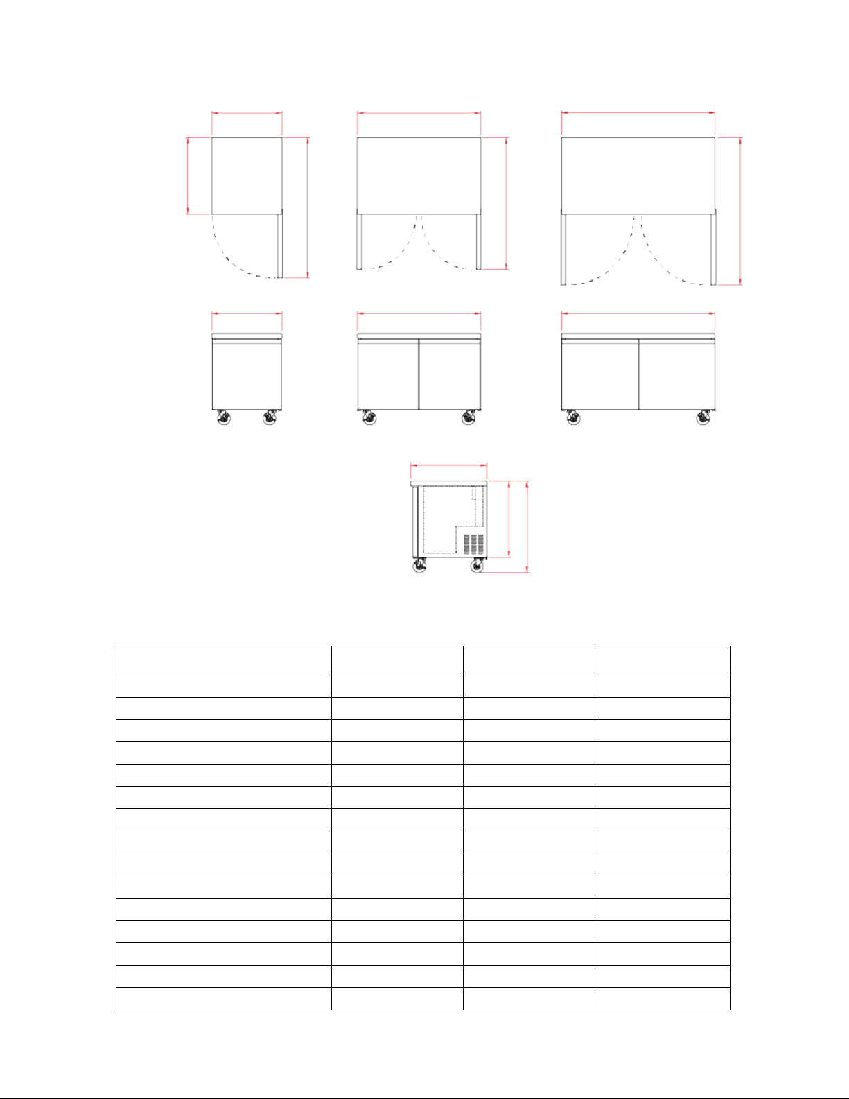
DIMENSIONS..................................................................................................................................................................................7!
TECHNICAL INFORMATION.......................................................................................................................................................7!
RECEIVING AND INSPECTING THE EQUIPMENT..................................................................................................................8!
INTRODUCTION
...........................................................................................................................................................................8!
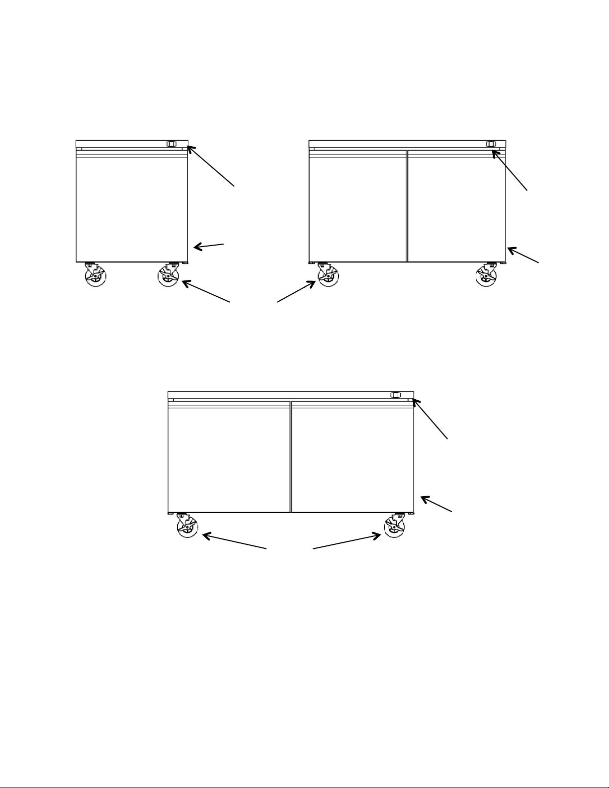
COMPONENT INFORMATION
..................................................................................................................................................9!
APPLIANCE INSTALLATION ....................................................................................................................................................10!
Remove Packaging Materials .....................................................................................................................................................10!
Location Requirements...............................................................................................................................................................10!
Inside cabinet: .............................................................................................................................................................................10!
Outside cabinet: ..........................................................................................................................................................................10!
Installation Clearance .................................................................................................................................................................11!
Leveling ......................................................................................................................................................................................11!
Stabilizing ...................................................................................................................................................................................11!
Electrical Connection..................................................................................................................................................................11!
OPERATION..................................................................................................................................................................................12!
Refrigerated cycle.......................................................................................................................................................................12!
Power Switch:.............................................................................................................................................................................12!
SOLID-STATE THERMOSTAT DESCRIPTIONS......................................................................................................................12!
1. FRONT PANEL COMMANDS.............................................................................................................................................12!
2. MAIN FUNCTIONS ..............................................................................................................................................................13!
3. ALARM SIGNALLING.........................................................................................................................................................13!
CLEANING AND MAINTENANCE............................................................................................................................................14!
Exterior and Interior Cleaning of Appliances.............................................................................................................................14!
Cleaning the Condenser Coil ......................................................................................................................................................14!
Stainless Steel Care and Cleaning ..............................................................................................................................................15!
Gasket Maintenance....................................................................................................................................................................15!
Doors/Hinges ..............................................................................................................................................................................15!
Drain Maintenance......................................................................................................................................................................15!
TROUBLESHOOTING GUIDE
.................................................................................................................................................16!
TROUBLESHOOTING .................................................................................................................................................................16!
WIRING DIAGRAMS ...................................................................................................................................................................17!