Krautzberger MP-400 User manual

Operating instructions
Diaphragm pump MP-400
Dok-236-GB-6bar.doc Rev. 0
Article No: 200-0102
-keep for further use-

Dok-236-GB-6bar.doc
2
CE Declaration of Conformity
in acc. with Annex II A of the EC Machine Directive 98/37/EC
Krautzberger GmbH
Stockbornstraße 13
65343 Eltville am Rhein
WE HEREBY DECLARE THAT THE FOLLOWING PRODUCT:
DESIGNATION
Diaphragm pump MP-400
UNIT NO. 200-0102
FUNCTION
Compressed air-driven pump for painting and coating
applications
COMPLIES WITH THE FOLLOWING PROVISIONS IN ITS DELIVERED VERSION
EG –Machine directive 98/37/EG
THE FOLLOWING HARMONISED EU STANDARDS WERE APPLIED:
DIN EN ISO 12100 1/2 DIN EN 1050
DIN EN 809 DIN EN 12639
THE FOLLOWING NATIONAL STANDARDS WERE APPLIED:
DIN 24289 Teil 1 und 2
DIN 24299 Teil 1 und 2
Date / Signature 25.11.2004, i.A.
Details of signatory Head of Design M.Stoffels
CE Declaration of Conformity
in acc. with Annex X of the EC Directive 94/9/EG (ATEX 100a)
WE HEREBY DECLARE THAT THE FOLLOWING PRODUCT:
DESIGNATION
Diaphragm pump MP-400
UNIT NO. 200-0102
FUNCTION
Compressed air-driven pump for painting and coating applications
complies with the following provisions in its delivered version:
ECDirective 94/9
THE FOLLOWING HARMONISED EU STANDARDS WERE APPLIED:
DIN EN 1127-1DIN EN 13463-1
THE UNIT BEARS THE FOLLOWING ADDITIONAL MARKING:
II 2 G c Notified body: 0637 IBExU
Date / Signature 25.11.2004, i.A.
Details of signatory Head of Design M.Stoffels

Dok-236-GB-6bar.doc
Contents
1USE FOR INTENDED PURPOSE ............................................................................. 4
2GENERAL SAFETY NOTES.................................................................................... 4
2.1 Important when using hazardous substances:.............................................................................5
3FUNCTIONAL PRINCIPLE ...................................................................................... 6
4INSTALLATION .................................................................................................... 6
5STARTUP ........................................................................................................... 7
6CLEANING .......................................................................................................... 7
7SHUTDOWN DURING INTERRUPTIONS TO WORK.................................................... 7
8DISPOSAL .......................................................................................................... 8
9TROUBLESHOOTING............................................................................................ 9
10 REGULAR CHECKS.............................................................................................. 9
10.1 Diaphragms and gaskets .............................................................................................................9
10.2 Hoses and pipelines .................................................................................................................. 10
11 MAINTENANCE.................................................................................................. 10
11.1 Replacing valve parts [Drawings on page 10]............................................................................ 10
11.2 Replacing the diaphragms [Drawings, page 11] ........................................................................ 10
12 TECHNICAL DATA.............................................................................................. 10
13 SPARE PARTS DRAWINGS.................................................................................. 11
14 SPARE PARTS LIST ........................................................................................... 12
14.1 Control unit ................................................................................................................................ 13
15 ACCESSORIES.................................................................................................. 14
15.1 Suction devices (flexible) ........................................................................................................... 14
15.2 Suction devices (angled, flexible) ..............................................................................................15
15.3 Suction devices (rigid) ............................................................................................................... 16
15.4 Pressure equalisation tank ........................................................................................................ 17
15.5 Pressure pipe............................................................................................................................. 18
3

Dok-236-GB-6bar.doc
1 USE FOR INTENDED PURPOSE
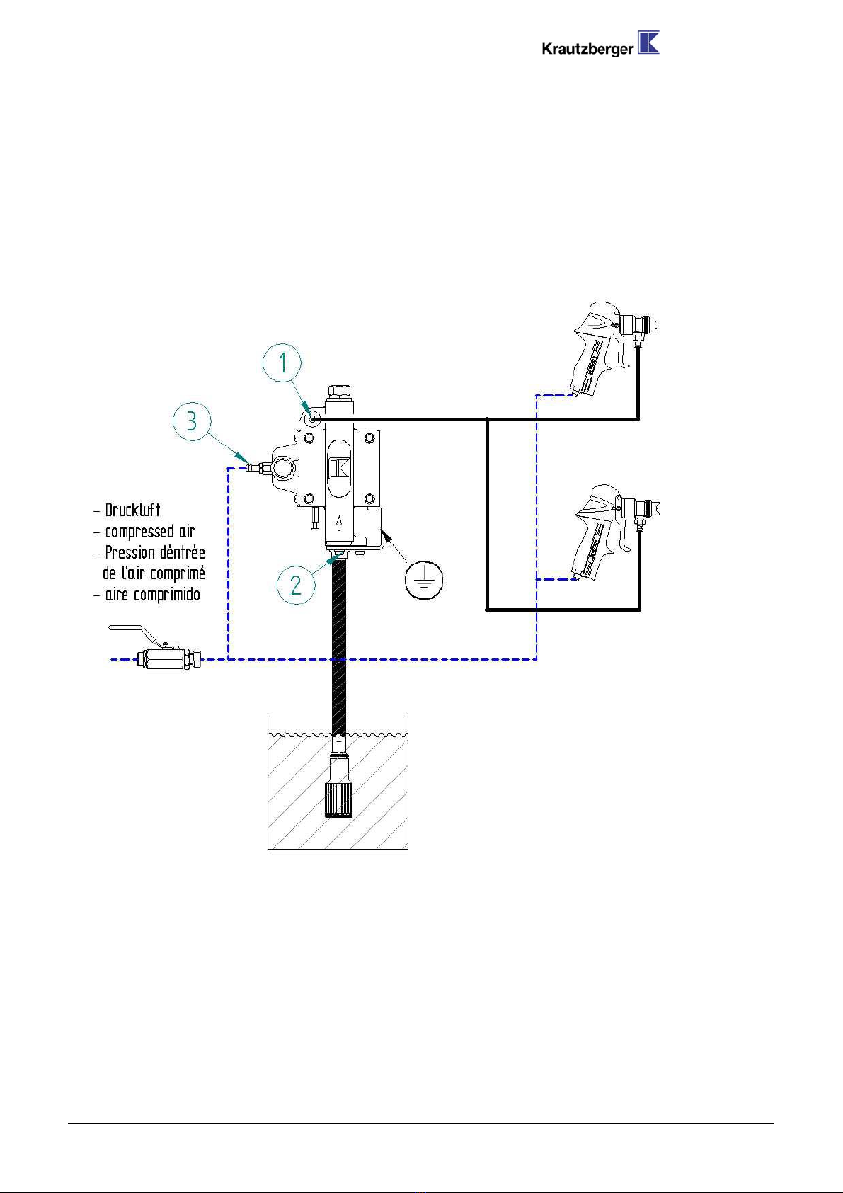
The diaphragm pump MP-400 is a pump driven by compressed air and is designed exclusively for
the:
conveying of liquid and low-viscosity coating material from pressureless storage containers
supply of material to spray guns, automatic spray guns, metering devices and similar
It is mainly used for painting and coating operations.
The diaphragm pump MP-400 complies with equipment category II 2G (ATEX 100a) and may be
operated in potentially explosive areas in "Zone 1".
When used in potentially explosive areas, the pump must be operated with a run-dry protection device
(e.g. filling level probe in the material container with auto pump switchoff feature)!
In addition, the diaphragms must be regularly checked for wear during safety inspections.
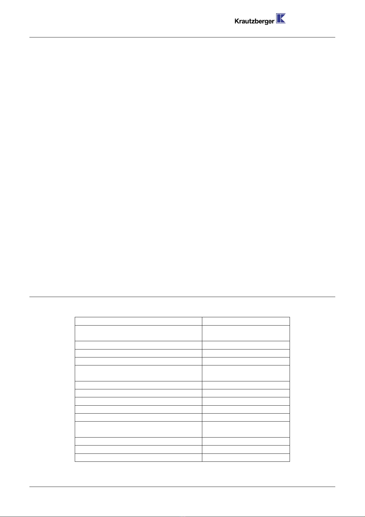
Material conveying properties
Material Suitability
Paints (containing solvents) good
Water-based paints, dispersion paints, Latex,
wood preservative good
Water good
Oils, fuel oil, diesel oil good
Emulsions, soaps, detergents good
Alcohol, glazing agents with qualifications
Lime slurry with qualifications
Cellulose and fibrous materials unsuitable
Paste Sludge, mash, paste unsuitable
In case of doubt, ask about the suitability of non-listed materials. In special cases,
we conduct trials to determine suitability.
2 GENERAL SAFETY NOTES
Diaphragm pumps may only be used in line with the operating parameters
(pressure, temperature etc.) specified under “Technical data”!
The operator must check the compatibility of the pump materials with the
coating substance to be used. To ensure compatibility, refer to the safety data
sheet supplied by the manufacturer of the coating substance!
All work connected with installation and maintenance must be performed by
suitably qualified personnel. Always use original parts when replacing worn or
damaged parts.
Each time before you start working, check the material and compressed air
connections for firm seat and damage! Loose, pressurised hoses may cause
accidents due to whiplash-like movement and the discharge of fluids.
4

Dok-236-GB-6bar.doc
Never point compressed air at people or animals!
Highly abrasive, chemically aggressive, extremely hot or extremely cold
materials may only be used in consultation with Krautzberger GmbH!
After the material has been used up, the pumps may only be operated at low
pressure (< 4 bar) – set on the air regulator.
No-load operation increases wear and may destroy the pump!
Ensure that the material container is always sufficiently full!
2.1 Important when using hazardous substances:
Always comply with the stipulations in the safety data sheet of the manufacturer
of the coating substance. In particular, adhere to instructions relating to:
the wearing of personal protective equipment
the avoidance of explosive or harmful environments
Electrostatic charges during operation of the pump can lead to electric shocks
and spark formation.
The pump must therefore be earthed!
Also earth air pipes, operating equipment and electrically conductive surfaces
in the working zone.
Connected hose lines must be conductive (<1 Mega-Ohm) and must also
be earthed.
Rooms in which hazardous substances are stored or processed must have
adequate ventilation. It may be necessary to install a technical ventilation
system.
If the ventilation system fails, work must be stopped immediately and the pump
switched off.
In such cases, always comply with the national and regional regulations.
Do not store any flammable substances, empty coating substance containers or
other materials that have been in contact with the coating substance (paper,
cloths etc.) in the working tone of the pump.
Do not use halogenated detergents. Chemical reactions may create explosive
and caustic compounds!
In the working zone, avoid open flames and red-hot components as well as
equipment, tools and parts that can create ignitable sparks.
Hang up “No Smoking” signs in a 5 metre radius of the working zone!
make fire extinguishers available if these are not already in place!
Comply with all national and regional water protection regulations!
Comply with all national and regional waste disposal regulations!
5

Dok-236-GB-6bar.doc
3 FUNCTIONAL PRINCIPLE
The pump consists of the diaphragm housing, the compressed air controller, material suction and
pressure connection, compressed air connection and air regulator.
The pressure desired at the extraction point can be adjusted steplessly via the air regulator.
As soon as the set material pressure is reached, the pump switches off automatically.
The material pressure is maintained until material is extracted at the extraction point. The pump
switches on automatically and keeps the set material pressure constant.
4 INSTALLATION
Mount the pump vertically (material inlet at bottom!) on a wall or a suitable supporting structure.
Correct operation of the pump is only assured if it is mounted vertically.
Connect the material suction hose to the material inlet (2).
At the material outlet, connect the material pressure hose to your extraction point (1).
Connect the compressed air supply at the air connection (3).
6

Dok-236-GB-6bar.doc
The compressed air supply must be dry, oil-free and protected using an overpressure
valve. Make the necessary provision for a suitable shutoff device (ball valve etc.) to
permit fast switch-off in the event of malfunction.
Connect the earthing device.
Always ensure that a run-dry protection device is present during use in potentially
explosive areas!
Ground the pump as well as conductive surfaces and working equipment in the potentially
explosive area
Check the firm seat of all connections!
5 STARTUP
Ensure that:
an air pressure of 4-12 bar is present at the compressed air connection.
the material suction hose is immersed in the material.
The first time the unit is started up, there is air in the pump and in the
supply line. The wear on the pump is particularly strong during no-load
operation.You should therefore set a low air inlet pressure on the air
regulator at the start. Activate the extraction point until material is
discharged.
After performing venting, set the desired material pressure using the air regulator.
6 CLEANING
Thoroughly clean the pump after use. Immerse the material suction hose in a suitable detergent.
OBSERVE THE SAFETY INSTRUCTIONS OF THE DETERGENT MANUFACTURER.
DETERGENTS CAN BE HARMFUL TO YOUR HEALTH AND MAY BE HIGHLY
FLAMMABLE!
OBSERVE THE SAFETY INSTRUCTIONS OF THE DETERGENT MANUFACTURER. DETERGENTS CAN BE
HARMFUL TO YOUR HEALTH AND MAY BE HIGHLY FLAMMABLE!
Rinse the pump through by activating the extraction point. To ensure that material residues do not
harden, you should leave the detergent in the pump until the next time it is used.
7 SHUTDOWN DURING INTERRUPTIONS TO WORK
Clean the pump as described above.
Close the air regulation wheel by turning to the left.
Interrupt the compressed air feed at a suitable point in your system.
Dissipate any remaining material pressure by activating the material extraction point.
7

Dok-236-GB-6bar.doc
8 DISPOSAL
Clean the pump if necessary to ensure that no residues of toxic, flammable or explosive material
remain in the housing.
After dismantling the pump:
Dispose of the individual components through the appropriate recycling channels.
Please observe the regulations of the local disposal companies.
8

Dok-236-GB-6bar.doc
9 TROUBLESHOOTING
Defect Cause Remedy
Loose/Leaky suction line Check/Tighten
Damaged gasket Replace
Air bubbles in
material container
Diaphragm damaged Replace
Foreign body in ball valve, or valve is worn Check ball valve, replace if
necessary
Air is sucked in Check suction device
Suction line blocked Check/Clean
Waste air line blocked Check/Clean
Uneven action of
pump
Soiled/Leaking valve ball/valve seat Clean/Replace
No working air Switch on and/or check compressed
air supply
Pump does not
start Pressure regulator defective Activate auxiliary actuator (34)
Replace pressure regulator
Suction filter soiled or suction hose bent Clean suction filter/Check suction
hose
Suction device leaky, air is sucked in Check gasket
Valve ball/Valve seat soiled Clean valve ball
Valve blocked Foreign body in valve; rinse out
pump
Valve seat or valve ball worn Replace valve seat/valve ball
Pump works but
does not build up
any pressure or
suction power
O-ring seal damaged Replace
Pressure
fluctuations during
operation
Different running
noise
Diaphragm worn Replace
Please contact our service department for assistance with other queries / problems.
10 REGULAR CHECKS
DURING ALL INSPECTION AND MAINTENANCE WORK:
BEFORE OPENING THE PUMP
CLEAN PUMP USING DETERGENT
SHUT OFF COMPRESSED AIR SUPPLY
DISSIPATE MATERIAL PRESSURE BY ACTIVATING THE EXTRACTION POINT
Maintenance intervals depend on the coating substance used and the mode of operation. These
intervals cannot therefore be exactly specified and must be determined by the user.
10.1 Diaphragms and gaskets
Diaphragms and gaskets are subject to natural wear and tear. We recommend regular safety
checks and replacement of diaphragms and gaskets. Always change the gaskets with the
diaphragms.
9

Dok-236-GB-6bar.doc
10.2 Hoses and pipelines
Even when handled correctly, the useful life of hoses and pipelines is always affected by
environmental factors. As a precautionary measure, all hoses and pipelines should be
regularly replaced (at intervals depending on the load to which they are subjected).
11 MAINTENANCE
11.1 Replacing valve parts [Drawings on page 10]
Shut off compressed air supply and dissipate any remaining material pressure
Unscrew sealing screws (10)
Remove and replace gasket (9), valve spring (8), valve ball (7), valve seat (6) with O-
ring seal (5)
Tighten sealing screws (10) - 90Nm
11.2 Replacing the diaphragms [Drawings, page 11]
Shut off compressed air supply and dissipate any remaining material pressure
Loosen screws (4) and remove cover (2)
Unscrew diaphragm (20) from control bolt (19)
Clean contact surfaces of cover and housing
Screw new diaphragms into control bolt
Replace O-ring seals (21)
Screw cover (2) on tight (2); arrow pointing upwards!
Tighten screws (4) - 20Nm
12 TECHNICAL DATA
MP-400
Conveying capacity (based on water,
8bar): 20 l/min (free outflow)
Material connection (outlet): G 1/2 female thread
Max. temperature of coating material: 0°C...+50°C
Max. pressure: 6 bar
Maximum admissible operating
pressure: 6 bar
Compressed air feed: non-lubricated, filtered
Compressed air connection: hose nozzle NW 8/9
Air inlet pressure: min. 4 to max. 8 bar
Transmission ratio: 1:1
Max. stroke rate (twin strokes): 120 twin str./min
Recommended stroke rate (twin
strokes): 100 twin str./min
Weight: 7.5 Kg
Air consumption (at 8bar): 160l/min
10

Dok-236-GB-6bar.doc
13 SPARE PARTS DRAWINGS
10
9
8
7
6
5
10
9
11
5
6
7
8
90Nm
4
3
2
20Nm
x
„x„-lightly grease parts
11
20
21
18 17 19 x
16
15
12
26
22
33
14
13
12
32
31
30 34
22
23
24 25
29
28
33
x
x

Dok-236-GB-6bar.doc
14 SPARE PARTS LIST
Item no. Article no. Designation Item no. Article no. Designation
1 6540-040-2136 Control housing 15 6542-030-2138 Sealing screw, brass
2 6540-040-2138 Cover 15 6543-030-2138 Sealing screw, brass
3 6540-030-2865 Washer 16 6540-030-2107 Intermed. piece, brass
4 6540-030-0562 Hex head screw 16 6541-040-0967 Intermed. piece, st. steel
5 6540-010-0291+ O ring seal, PTFE 16 6542-030-2107 Intermed. piece, brass
5 6541-010-0291+ O ring seal, PTFE 16 6543-030-2107 Intermed. piece, brass
5 6542-010-0335+ O ring seal, NBR 17 6540-040-0961 Headed liner
5 6543-010-0291+ O ring seal, PTFE 18 6540-010-0197+ Slotted ring
6 6540-040-0962++ Valve seat, st. steel 19 6540-040-0959 Control bolt
6 6541-040-0962++ Valve seat, st. steel 20 6540-010-0455++ Diaphragm, PTFE
66542-080-0369++Valve seat,HM20 6541-010-0455++Diaphragm,PTFE
66543-080-0369++Valve seat,HM20 6542-010-0451++Diaphragm,NBR
7 6540-030-2753++ Valve ball, st. steel 20 6543-010-0455++ Diaphragm, PTFE
7 6541-030-2753++ Valve ball, st. steel 21 6540-010-0199+ O ring seal
7 6542-030-2752++ Valve ball, PUR 22 6540-030-0564 Screw
7 6543-030-2754++ Valve ball, HM 23 6540-040-0958 Cover panel
8 6540-020-0081 Valve spring 24 6540-030-0441 Set screw
9 6540-010-0307+ Gasket 25 6540-040-0957 Control unit
10 6540-040-0964 Sealing screw, brass 6540-080-5946 Control unit w. stroke limit
10 6541-040-0968 Sealing screw, st. steel 26 6540-100-0427 Cover hood
10 6542-040-0964 Sealing screw, brass 27 6540-030-2894 Serrated lock washer
10 6543-040-0964 Sealing screw, brass 28 6540-030-2862 Washer
11 6540-040-0965 Distance cage 29 6540-030-0274 Cheese head screw
12 6540-040-0963 Double nipple, brass 30 6540-040-0960 Holder
12 6541-040-0966 Double nipple, st. steel 31 6540-030-1982 Lock washer
12 6542-040-0963 Double nipple, brass 32 6540-030-0563 Cheese head screw
12 6543-040-0963 Double nipple, brass 33 6540-130-0281 Control unit, cmpl.
13 6540-010-0198+ Gasket 34 6540-080-2345 Auxiliary actuator
14 6540-040-1246 Union nut 6540-010-0442 Gasket set
15 6540-030-2138 Sealing screw, brass 6540-080-1455 Set of wearing parts
15 6541-030-0561 Sealing screw, st. steel (incl. gasket set)
+ included in gasket set
++ included in set of wearing parts
12

Dok-236-GB-6bar.doc
14.1 Control unit
1 6540-010-0203+
2 6540-030-2427 Swiv
3 6540-110-0101
4 6540-030-2207
5 6540-010-0203+
6 6540-030-0565
7 6540-030-0707
8 6540-010-0244+
9 6540-040-0954
10 6540-030-1855
11 6540-030-1444++
12 6540-010-0046+
13 6540-010-0150+
14 6540-010-0146+
15 6540-030-0707
16 6540-030-0147
17 6540-080-2465 C
18 6540-030-3235
19 6540-030-3237++
20 6540-010-0494+
21 6540-010-0056+
22 6540-030-3236 S
23 6540-030-0212
24 6540-130-0217 Pres
25 6540-080-2464 Pl
6540-010-0696
6540-080-1452 S
Gasket
el screw connection
Air hose
Hose nozzle
Gasket
Screw
Circlip
Gasket
Valve adapter
Fastening nipple
Sound absorber
Gasket
Gasket
Gasket
Circlip
Screw
ontrol valve, cmpl.
Housing
Control piston
Gasket
Gasket
tem valve, cmpl.
Screw
sure regulator,cmpl.
unger valve, cmpl.
Gasket set
et of wearing parts
incl. gasket set
13

Dok-236-GB-6bar.doc
15 ACCESSORIES
Pressure equalisation tank with screw-off cleaning cover and pressure gauge for equalisation of
pulsation and indication of the set material pressure
Suction devices in various versions, with filter basket
Pressure pipe with pressure gauge for indication of the set material pressure
Material filter with drain valve
Material pressure regulator for absolutely constant material pressure, even in extremely low pressure
ranges
Pneumatic pump lifting devices
Trolley with storage space
Wall brackets
Stand for holding a wall bracket
Tank cover for diaphragm pump mounting
Holder for cover mounting
Material drain valve
Other accessories in request
15.1 Suction devices (flexible)
Item no. Article no. Designation
S
uction cage
Ø
Hose length (mm )
9000-080-0776 Suction device, cmpl. 42 +
9000-080-0777 Suction device, cmpl. 80 +
9000-080-0778 Suction device, cmpl. 42 750
9000-080-0779 Suction device, cmpl. 80 750
1 9000-080-0014 Suction cage 42
1 9000-080-0066 Suction cage 80
2 9000-030-1396 Hose clamp
3 9000-040-0887 Suction piece
4 9000-040-1246 Union nut
5 9000-040-1300 Hose nozzle
6 9000-110-0013 Suction hose +
6 9000-110-0005 Suction hose 750
7 9000-030-1397 Hose clamp
+ When ordering, please state hose length in mm
14

Dok-236-GB-6bar.doc
15.2 Suction devices (angled, flexible)
Item no. Article no. Designation Dim. A
S
uction cage
Ø
Hose length (mm )
9000-080-1714 Suction device, cmpl. 440 42 +
9000-080-1715 Suction device, cmpl. 440 80 +
9000-080-1716 Suction device, cmpl. 920 42 +
9000-080-1717 Suction device, cmpl. 920 80 +
9000-080-0288 Suction device, cmpl. 440 42 750
9000-080-0298 Suction device, cmpl. 440 80 750
9000-080-0774 Suction device, cmpl. 920 42 1100
9000-080-0775 Suction device, cmpl. 920 80 1100
9000-080-2331 Suction device, cmpl. 1100 80 1000
1 9000-080-0014 Suction cage 42
1 9000-080-0066 Suction cage 80
2 9000-030-1396 Hose clamp
3 9000-040-0886 Suction pipe 440
3 9000-040-1897 Suction pipe 920
3 9000-040-3864 Suction pipe 1100
4 9000-040-1246 Union nut
5 9000-040-1300 Hose nozzle
6 9000-110-0013 Suction hose +
6 9000-110-0005 Suction hose 750
6 9000-110-0093 Suction hose 1100
7 9000-030-1397 Hose clamp
8 9000-080-3511 Screw connection
+ When ordering, please state hose length in mm.
15

Dok-236-GB-6bar.doc
15.3 Suction devices (rigid)
Applications
Ite
mArticle no. Designation Dim.
A
Suction
cage Ø
MP
400
MP
100
25 l
(1)
120 l
(2)
200 l
(3)
Pressureless
Krautzberger
9000-090-0118 Suction device, cmpl. + 42 X
9000-090-0119 Suction device, cmpl. + 80 X
9000-090-0120 Suction device, cmpl. + 42 X
9000-090-0121 Suction device, cmpl. + 80 X
9000-090-0122 Suction device, cmpl. 405 42 X X
9000-090-0123 Suction device, cmpl. 795 42 X X
9000-090-0124 Suction device, cmpl. 885 42 X X
9000-090-0125 Suction device, cmpl. 405 42 X X
9000-090-0126 Suction device, cmpl. 795 42 X X
9000-090-0127 Suction device, cmpl. 885 42 X X
9000-090-0128 Suction device, cmpl. 405 80 X X
9000-090-0129 Suction device, cmpl. 795 80 X X
9000-090-0130 Suction device, cmpl. 885 80 X X
9000-090-0131 Suction device, cmpl. 405 80 X X
9000-090-0132 Suction device, cmpl. 795 80 X X 200 I / 250 l
9000-090-0133 Suction device, cmpl. 885 80 X X
9000-090-2844 Suction device, cmpl. 547 80 X 50 l
9000-090-1278 Suction device, cmpl. 540 80 X 50 l
9000-090-1279 Suction device, cmpl. 640 80 X 100 l / 150 l
9000-090-1283 Suction device, cmpl. 940 80 X 300 l / 350 l / 400 l
9000-090-1284 Suction device, cmpl. 1040 80 X 450 l / 500 l
1 9000-080-0014 Suction cage 42
1 9000-080-0066 Suction cage 80
2 9000-030-1396 Hose clamp
3 9000-080-0076 Suction pipe + X
3 9000-080-0077 Suction pipe + X
3 9000-080-0078 Suction pipe 405 X X
3 9000-080-0079 Suction pipe 795 X X
3 9000-080-0080 Suction pipe 885 X X
3 9000-080-0081 Suction pipe 405 X X
3 9000-080-0082 Suction pipe 795 X X 200 l / 250 l
3 9000-080-0083 Suction pipe 885 X X
3 9000-080-3140 Suction pipe 547 X 50 l
3 9000-080-1325 Suction pipe 540 X 50 l
3 9000-080-1326 Suction pipe 640 X 100 l / 150 l
3 9000-080-1330 Suction pipe 940 X 300 l / 350 l / 400 l
3 9000-080-1331 Suction pipe 1040 X 450 l / 500 l
4 9000-040-1246 Union nut
1) 25 l hobbock container, height 385 mm
2) 120 l plastic standard barrel, height
795mm
3) 200 l barrel with lid M7 DIN 6644,
height 871 mm
+ When ordering, please state
dimension A!
16

Dok-236-GB-6bar.doc
15.4 Pressure equalisation tank (only 8bar!)
Pressure equalisation tank, cmpl. (brass screw connection 9040-090-0088 )
Item no. Article no. Designation
9040-090-0088 Pressure equalis. tank, cmpl.
1 9040-080-0098 Container, cmpl.
2 9040-100-0475 Cover
3 9040-010-0162 Gasket
4 9040-030-1039 Pressure gauge, 0-10 bar
9040-080-0099 Cover, cmpl.
comprising items 2 to 4
Pressure equalisation tank, cmpl. (stainless steel screw connection 9041-090-0087 )
Item no. Article no. Designation
9041-090-0087 Pressure equalis. tank, cmpl.
1 9041-080-0097 Container, cmpl.
2 9041-100-0475 Cover
3 9041-010-0162 Gasket
4 9041-030-1039 Pressure gauge, 0-10 bar
9041-080-0099 Cover, cmpl.
comprising items 2 to 4
17

Dok-236-GB-6bar.doc
18
15.5 Pressure pipe
Pressure pipe, cmpl.(brass, 9035-080-0338 )
Item no. Article no. Designation
9035-080-0338 Pressure pipe, cmpl.
1 9035-080-0340 Pressure pipe
2 9035-040-1246 Union nut
3 9035-030-1039
P
ressure gauge, 0-10 ba
r
Pressure pipe, cmpl., stainless steel 9036-080-0339 )
1 9036-080-0340 Pressure pipe
2 9036-040-1246 Ünion nut
3 9036-030-1039
P
ressure gauge, 0-10 ba
r
Other manuals for MP-400
2
Table of contents
Other Krautzberger Water Pump manuals
Popular Water Pump manuals by other brands

Interpump
Interpump Pratissoli KT-WK Series Repair manual

Becker
Becker DTLF 400 operating instructions

teel
teel 4RJ58 Operating instructions & parts manual

Kodiak
Kodiak PSP125ABK Installation, operation & maintenance manual

VERDER
VERDER Verderair VA-E80 Operation

HEISSNER
HEISSNER HSP600-i Instructions for use

Atlas Copco
Atlas Copco D500 Product instructions

Spowdi
Spowdi Pro MKII installation manual

Amazon
Amazon B07SR159QF manual

Wilo
Wilo Drain TMT 32M Installation and operating instructions

Crivit
Crivit 285656 instruction manual

Kessel
Kessel Aqualift F Standard Installation, operating and maintenance instructions