Krell Industries Showcase DVD Assembly instructions

HDMI Upgrade
for the
Showcase DVD
INSTALLATION AND SETUP GUIDE
Getting Started
THE LEADER IN AUDIO ENGINEERING
Thank you for your purchase of the HDMI Digital Video Output Stage for the Krell
Showcase DVD. HDMI combines high definition video and multi-channel audio in
a single digital interface, and is fully backward compatible with the Digital Visual
Interface (DVI) standard. The HDMI Digital Video Output Stage utilizes an on
board video scaler that converts standard DVD video from the native 480i resolu-
tion to high-definition resolutions, 480p, 720p, or 1080i.
This document outlines the basic steps for unpacking the HDMI boards and acces-
sories that comprise the HDMI Digital Video Output Stage and describes the proce-
dure for installing them into the Showcase DVD. The owner’s reference for the
Showcase DVD, including a detailed description of features and the product warran-
ty, is available on the web at:
www.krellonline.com
Please contact your authorized dealer, distributor, or Krell if you have any ques-
tions not addressed in this installation guide.
Follow these steps to safely unpack the shipping box. Only one person needed:
1. Open the shipping box and remove the top layer of foam. You see these items:
Quantity Description Part Number
1 SC DVD 5V P/S PCB (HDMI power PCB) 307221-TK
1HDMI adapter PCB 307124-TK
16-pin, 12-inch JST cable 307294
1 8-pin, 12-inch JST cable 307295
122-pin, 4-inch flat FFC cable 307297
1 22-pin, 2-inch flat FFC cable 307296
4 4-40 x 1/2-inch SHSC 301413
3 4-40 x 1/4-inch SHSC 301416
14-40 x 3/4-inch SHSC 302600
1 4-40 x 3/8-inch FHTS 304972
1 1/4 hex 4-40 x 1-1/2-inch standoff 307291
14-40 Kepnut 302660
4 Ty-Wraps 302816
1 Installation and Setup Guide 308022
1HDMI Owner’s Reference 307463
2. Remove the HDMI boards and place them in a safe location, in your working
area. Remove the protective plastic wrapping.
3. Remove the accessories and place them in a safe location, in your working area,
in preparation for the installation process.
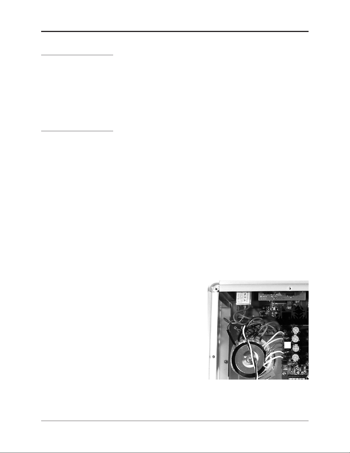
Place the Showcase DVD on a firm, level surface in your working area, away from
excessive heat, humidity, or moisture. Follow the installation procedure for the HDMI
upgrade described on pages 2-7.
THERE ARE NO USER-
SERVICEABLE PARTS INSIDE
ANY KRELL PRODUCT.
Krell authorizes this HDMI
upgrade to the Showcase DVD
to be performed only by Krell
authorized dealers, Krell author-
ized distributors, or the Krell fac-
tory.
Unpacking
Note
Save all packing materials.
If you need to ship the HDMI
upgrade kit in the future, repack
the unit in its original packaging
to prevent shipping damage.
IMPORTANT
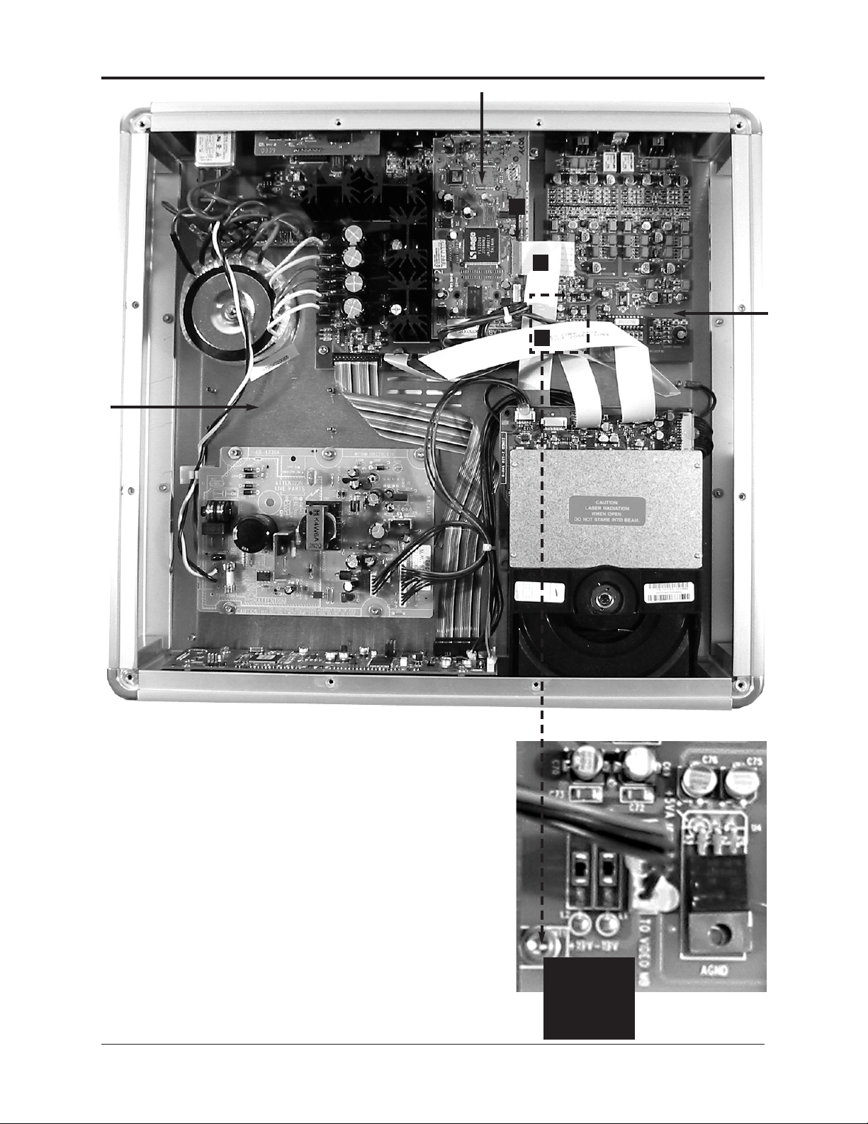
The HDMI MAIN PCB contains
static sensitive components.
Take proper static precautions
during the HDMI upgrade
procedure.
Showcase DVD / 1
HDMI Upgrade
Placement
This product complies with the EMC directive (89/336/EEC) and
the low-voltage directive (73/23/EEC).

Follow steps A – Z to install the HDMI board and related components into the Krell
Showcase DVD. You will need the following tools, not provided in the installation kit:
one 3/32 Allen wrench one T-15 Torx wrench
one 1/4-inch nut driver one T-10 Torx wrench
Make sure that the Showcase DVD is unplugged from AC power.
Steps A–D. Prepare the Showcase DVD For Installation
A. Remove the 12 T-15 Torx screws from the top cover of the Showcase DVD.
B. Set the cover aside.
C. Remove the two 440 7/16-inch hex screws (1) and nuts that secure the access
plate (2) on the back panel of the Showcase DVD (see Figure 1).
D. Set the hex screws, nuts, and access plate aside.
Steps E–I. Prepare the Progressive Output PCB and Analog Output
PCB For HDMI Upgrade.
E. Release the 22-pin, 7-inch flat digital video cable (3) from the locking socket (4)
on the progressive output PCB (see Figure 2).
To release a cable from a locking socket, pull the two tabs back, away from the
cable, at either end of the locking socket. To reset the locking socket, push the
tabs on the locking socket toward the cable.
F. Unscrew the 4-40 x 7/16-inch hex screw (5) from the pin standoff at MT1, on the
front left corner of the analog output PCB (see Figure 2 inset), and remove the
screw and its washer. Notice the MT1 through hole and the pin standoff below the
through hole (not illustrated). The pin standoff is attached to the chassis.
G. Turn the DVD Standard on its side to perform Steps H and I.
H. Insert and thread the supplied 4-40 x 3/4-inch screw through the bottom of the
chassis into the pin standoff. Notice that the screw protrudes up from the pin
standoff (not illustrated).
I. Thread the supplied 1-1/2-inch standoff onto the screw protruding through the
MT1 hole. (not illustrated).
2 Showcase DVD /
HDMI Upgrade
Figure 1
Showcase DVD
Back Panel
1 Hex screw
2 Access plate
HDMI Upgrade
Procedure
This product is manufactured in the United States of America. Krell®is a registered trademark of Krell Industries, Inc., and is restricted for use
by Krell Industries, Inc., its subsidiaries, and authorized agents. HDMI, the HDMI logo, and High-Definition Multimedia Interface are trademarks
or registered trademarks of HDMI Licensing LLC. All other trademarks and trade names are registered to their respective companies.
© 2004 by Krell Industries, Inc., All rights reserved
2
1

Figure 2
Showcase DVD Interior,
Before HDMI Upgrade
Installation
322-pin, 7-inch flat digital video
cable
4 Locking socket
54-40 x 7/16-inch hex screw.
The pin standoff is below this
screw.Figure 2 Inset
Analog Output PCB,
Left Front Corner
54-40 x 7/16-inch hex screw.
The pin standoff is below this
screw.
Showcase DVD / 3
HDMI Upgrade
4
3
5
5 Lift the cables
to expose the
through hole at
MT1 on the ana-
log output PCB.
Progressive output PCB
Analog
output
PCB
Position the
HDMI power
PCB here. (See
pages
4-5.)

Steps J–M. Install the HDMI Adapter PCB
J. Locate the HDMI connector on the back edge of the supplied HDMI adapter PCB
(not illustrated) and slide it into the HDMI connector through hole (6) on the back
panel (see Figure 3) of the Showcase DVD.
K. Secure the HDMI adapter PCB to the back panel using two supplied 4-40 x 1/4-
inch SHSC (7) (see Figure 3).
L. Position the left front through hole on the HDMI adapter PCB over the standoff
protruding up from the analog output board (not illustrated).
M. Thread one supplied 4-40 x 1/4-inch SHSC (28) onto the standoff to support the
front left corner of the HDMI adapter PCB (see Figure 4).
Steps N–P. Install the HDMI Power PCB
N. Mount the supplied HDMI power PCB onto the Showcase DVD chassis using the
four supplied 4-40 x 1/2-inch SHCS (8); one in each corner of the board. (see
Figure 4).
O. Secure the regulator to the chassis with the supplied 4-40 x 3/8-inch FHTS (9)
and cap it with the supplied 4-40 Kepnut (10) (see Figure 4).
P. Tighten until “just snug”. The torque spec is 5-8 in lbs.
76
Figure 3
Showcase DVD Back Panel
Showing HDMI Connector,
After HDMI Adapter PCB Is
Installed
6Connector through hole with
HDMI connector in place
7 two 4-40 x 1/4-inch SHSC
4 Showcase DVD /
HDMI Upgrade
Audio sync switch

Showcase DVD / 5
HDMI Upgrade
HDMI power PCB
8
28
8
8
8
9
10
Figure 4
Showcase DVD Interior,
With HDMI Adapter PCB and
HDMI Power PCB Installed
84-40 x 1/2-inch SHCS
9 4-40 x 3/8-inch FHTS (below
Kepnut)
10 4-40 Kepnut
28 4-40 x 1/4-inch SHSC
HDMI
adapter
PCB
Regulator

Steps Q–Y. Connect the Cables
Q. Release the 22-pin, 10-inch flat cable (22) from J1603 (23) on the drive PCB
(This cable is affixed to the main power supply PCB. Not illustrated).
R. Connect the 22-pin, 10-inch flat cable (22) to connector J29 (24) on the HDMI
adapter PCB. Orient the contacts to face the front of the Showcase DVD.
S. Connect the supplied 22-pin, 2-inch flat cable (11), with the contacts facing up,
from J1002 (4) on the progressive output PCB to connector J4 (12) on the HDMI
adapter PCB. Reset the tabs to lock the socket on J1002 (see Figure 5).
T. Connect the supplied 6-pin JST cable (13) from connector J7 (14) on the HDMI
adapter PCB to connector J3 (15) on the HDMI power PCB (see Figure 5).
U. Unplug the two white transformer wires (16) from the main power PCB (see
Figure 5 inset) and connect them to connectors J1 (17) and J2 (18) on the HDMI
power PCB (see Figure 5). Polarity is not an issue.
V. Connect the supplied 8-pin JST cable (19) from connector J12 (20) on the HDMI
adapter PCB to connector J6 (21) on the front panel PCB (see Figure 5).
W.Connect the 22-pin, 4-inch flat cable (25) from connector J1603 (26), on the
HDMI adapter PCB to connector J1603 (23) on the drive PCB. Orient the con-
tacts from J1603 (26) to face the front of the Showcase DVD.
X. Connect the 22-pin, 7-inch, flat digital video cable (3) (previously disconnected in
Step E) to connector J1506 (27) on the HDMI adapter PCB. Orient the contacts
so that they are facing toward the back of the unit.
Y. Position jumper JMP2 on the faceplate board so that it is across pins 1-2 , the
middle and right-hand pins as you face the front of the unit. (not illustrated)
Step Z. Replace the Top Cover Of the Showcase DVD
Z. Replace the top cover using the 12 T-15 Torx screws (set aside in Step B above).
The Showcase DVD is ready for operation with the HDMI Digital Video Ouput Stage
installed.
6 Showcase DVD /
HDMI Upgrade
HDMI Upgrade
Procedure, continued
Figure 5 Inset
2 White Transformer Wires,
Main Power PCB
16 2 white transformer wires
connected to the main power
PCB
16
IMPORTANT
To unplug a transformer wire,
pull the female fast-on connector
at the end of the wire. If you pull
the wire itself, instead of the
connector, the wire may detach
from the connector.
Note
Remove the plastic tags from
the supplied cables and wires,
before continuing the installa-
tion. Add the Ty-Wrap plastic
tags to cables, if needed, to
keep them neatly positioned
inside the chassis.

Figure 5
Showcase DVD Interior,
With HDMI Upgrade
Completed
3 22-pin, 7-inch flat cable
4 Connector J1002
11 22-pin, 2-inch flat cable
12 Connector J4
13 6-pin JST cable
14 Connector J7
15 Connector J3
16 2 white transformer wires
17 Connector J1
18 Connector J2
19 8-pin JST cable
20 Connector J12
Showcase DVD / 7
HDMI Upgrade
17
1616
16
12
13
23
14
15
19
18
22
20
21
25
24
26
3
27
21 Connector J6
22 22-pin, 10-inch flat cable
23 Connector J1603 on the drive
PCB
24 Connector J29
25 22-pin, 4-inch flat cable
26 Connector J1603 on the HDMI
adapter PCB
27 Connector J1506
11
4
Progressive output PCB
Front panel PCB
HDMI power PCB
Main power PCB
HDMI
adapter
PCB
Drive
PCB

Krell Industries, Inc., 45 Connair Road,Orange, CT 06477-3650 USA
WEB SITE http://www.krellonline.com
Connections
HDMI CONNECTIONS
Questions and
Answers
Follow these steps to connect the Showcase DVD with HDMI to your system.
1. Make sure all power sources and components are off before connecting inputs
and outputs.
2. Neatly organize the wiring between the Showcase DVD and all system compo-
nents. Separate AC wires from audio cables to prevent hum or other unwanted
noises from being introduced into the system.
3. Connect the desired Showcase DVD video output to the appropriate video input
of your video component, for example to the video input of a preamp/processor.
Connect the output of the HDMI Digital Video Output Stage to a HDMI or DVI
compatible display device using a HDMI-to-HDMI or HDMI-to-DVI cable. For
HDMI-to-HDMI and HDMI-to-DVI connections, set the Audio Sync switch (see
Figure 3) located on the rear panel to “on”. Audio Sync synchronizes audio and
video signals to align precisely. Set the Audio Sync switch located on the rear
panel to “off” whenever you are using component, S-video, or composite video
outputs and coax or optical audio outputs.
4. Connect a digital audio output to an appropriate digital audio input.
5. Connect balanced or single-ended analog outputs if desired.
6. Plug the AC power cord into the IEC connector (39) on the back panel, then plug
the AC power cord into the wall socket. The red stand-by LED (3) on the front
panel illuminates.
Power on the Showcase DVD and turn on your HDCP-compatible display device.
The HDMI Digital Video Output Stage detects the HDMI or DVI compatible circuitry
in the display device, and one of the three HDMI LED’s on the front panel illumi-
nates. Push the HDMI button to cycle through available resolutions: 480p, 720p, and
1080i.
When powering up any system, always turn amplifiers on last. When powering
down, always turn amplifiers off first.
For further information on how to operate the Showcase DVD, please refer to the
Showcase DVD Owner’s Reference on the website at www.krellonline.com.
Q. Where do I obtain a HDMI-to-HDMI or HDMI-to-DVI cable?
A. HDMI-to-HDMI or HDMI-to-DVI cables are available from most major cable manu-
facturers. Consult your local Krell dealer or distributor.
Q. Are component, S-video, and composite video outputs active while the HDMI
Digital Video Output Stage is in use?
A. Yes.
Q. Are the analog and digital audio outputs active while the HDMI Digital Video
Output Stage is in use?
A. Yes.
Q. What is HDCP?
A. HDCP stands for High-bandwidth Digital Content Protection. HDCP is a form of
copyright protection designed for digital entertainment content. The HDMI Digital
Video Output Stage is a HDCP compliant device, and will only work with other
HDCP compliant devices.
8 Showcase DVD /
HDMI Upgrade
P/N 308022-W
v 04.1
HDMI Operation
Notes
Other manuals for Showcase DVD
5
Table of contents
Other Krell Industries DVD Player manuals

Krell Industries
Krell Industries DVD Standard Quick start guide

Krell Industries
Krell Industries Evolution 525 User manual

Krell Industries
Krell Industries DVD Player User manual

Krell Industries
Krell Industries Showcase DVD User manual

Krell Industries
Krell Industries Showcase DVD User manual

Krell Industries
Krell Industries S-350 User manual