Kremlin-Rexson CYCLOMIX MICRO+ User manual

INSTRUCTION MANUAL
CYCLOMIXTM
MICRO, MICRO +
MICRO + PH
MIXING MACHINE
Manual : 1412 573.191.112
Date : 15/12/14 - Cancels : 25/06/13
Modif.: Update
TRANSLATION FROM THE ORIGINAL MANUAL
IMPORTANT : Before assembly and start-up, please read and clearly understand all the
documents relating to this equipment (professional use only).
THE PICTURES AND DRAWINGS ARE NON CONTRACTUAL. WE RESERVE THE RIGHT TO MAKE CHANGES WITHOUT PRIOR
NOTICE.
KREMLIN - REXSON
l
150, avenue de Stalingrad
93 245 - STAINS CEDEX – France
: 33 (0)1 49 40 25 25 Fax : 33 (0)1 48 26 07 16
www.kremlin-rexson.com

KREMLIN REXSON Page 1 Manual : 573.191.112
INSTRUCTION MANUAL
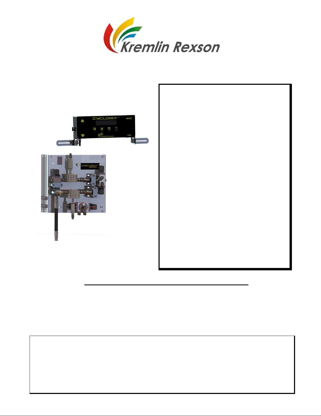
CYCLOMIXTM MICRO, MICRO + & MICRO + PH
MIXING MACHINE
TABLE OF CONTENTS
1. GENERAL SAFETY INSTRUCTIONS ......................................................................................................... 3
INSTALLATION REQUIREMENTS ............................................................................................ 3
EQUIPMENT REQUIREMENTS................................................................................................. 3
MAINTENANCE REQUIREMENTS............................................................................................ 4
ENVIRONMENT.......................................................................................................................... 5
2. DESCRIPTION ............................................................................................................................................. 5
3. OPERATING PRINCIPLE ............................................................................................................................ 7
4. TECHNICAL FEATURES............................................................................................................................. 8
5. INSTALLATION ......................................................................................................................................... 10
DESCRIPTION OF THE LABEL MARKINGS........................................................................... 10
INSTALLATION DIAGRAM....................................................................................................... 11
IMPLANTATION ....................................................................................................................... 12
CONNECTION OF THE CONTROL BAY AND OF THE FLUID PART.................................... 14
6. OPERATING .............................................................................................................................................. 15
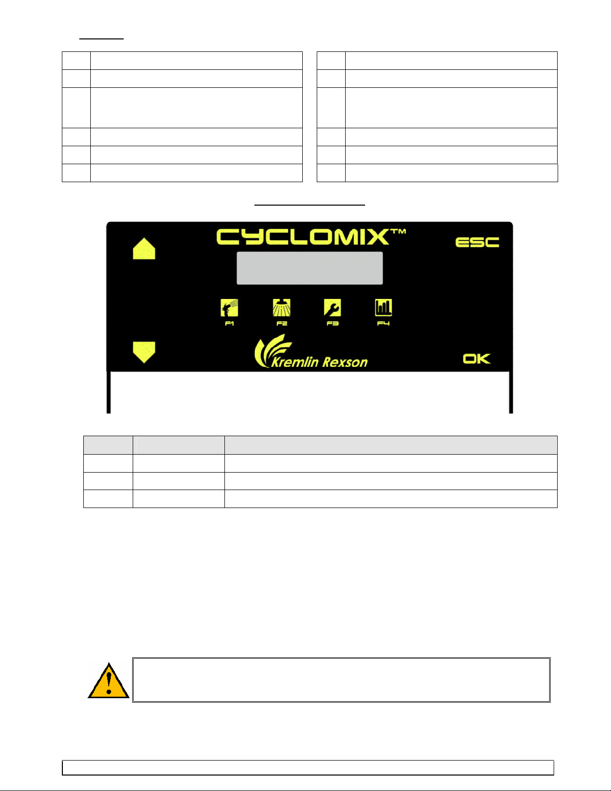
DRIVING FROM THE MACHINE.............................................................................................. 15
SWITCHING ON THE MACHINE ............................................................................................. 15
7. FIRST SWITCHING ON ............................................................................................................................. 16
8. FIRST PLACING INTO OPERATION......................................................................................................... 18
FLUSHING OF THE PUMPS AND OF THE MACHINE INTO SOLVENT................................ 18
START-UP OF THE MACHINE ................................................................................................ 18
9. APPLICATION PROGRAMMING (F3)....................................................................................................... 19
PASSWORD ............................................................................................................................. 19
PROCEDURE TO GET THE VERSION NUMBER OF THE ELECTRONIC CARD................. 19
PARAMETERS FOR MACHINE WITHOUT CATALYST FLUSHING ...................................... 20
PARAMETERS FOR MACHINE WITH CATALYST FLUSHING.............................................. 21
10. PRODUCTION (F1).................................................................................................................................... 23
PROPORTIONING TEST ......................................................................................................... 24
11. FLUSHING (F2).......................................................................................................................................... 24
12. CONSUMPTIONS / PRINT (F4) ................................................................................................................. 26
13. DOWNLOADING DATA FROM CYCLOMIX MICRO TO A COMPUTER.................................................. 27
14. INDICATIONS GIVEN BY THE LEDS........................................................................................................ 31
15. MAINTENANCE ......................................................................................................................................... 31
TROUBLESHOOTING.............................................................................................................. 33
DIAGNOSTICS ......................................................................................................................... 34
16. DISASSEMBLY - REASSEMBLY.............................................................................................................. 36
MIXER....................................................................................................................................... 36
FLOWMETER ........................................................................................................................... 36
PILOTED VALVES (FLUID VALVES AND TEST VALVES) ..................................................... 37

KREMLIN REXSON Page 2 Manual : 573.191.112
ADDITIONAL DOCUMENTATIONS :
Declaration EC declaration of conformity Doc. 578.034.130-UK
Annexes Pneumatic & electric diagrams
Mixing ratio chart
Doc. 573.191.120
Spare parts CyclomixTM micro Doc. 573.359.050
Color changer Doc. 573.186.112 + 573.187.050 + 573.188.050
CyclomixTM : Flowmeters and sensors
replacement
Doc. 573.705.070

KREMLIN REXSON Page 3 Manual : 573.191.112
Dear Customer, You are the owner of our new CYCLOMIXTM MICRO mixing machine and we would
like to take this opportunity to thank you.
To make sure your investment will provide full satisfaction, special care has been taken by KREMLIN
during all designing and manufacturing processes. To obtain the best result, safe and efficient
operation of your equipment, we advice you to read and make yourself familiar with this instruction
and service manual.
1. GENERAL SAFETY INSTRUCTIONS
The CYCLOMIXTM MICRO mixing machine shall be installed outside the explosive
area. It shall be installed in a safe area (non-explosive area according to the ATEX
directive - refer to § 6).
The display unit must be moved 1 m / 3.3 ft away from the fluid module and not be
installed above that one.
WARNING : Any misuse of the equipment or accessories can damage them, result in serious body
injury, fire or explosion hazard and reduce the equipment working life. Read carefully the safety
instructions hereafter.
The personnel involved in operating and servicing this equipment must be aware of all safety requirements
stated in this manual. The workshop supervisor must be certain that the personnel has perfectly
understood the safety instructions and complies with them.
Read all instruction manuals as well as the tags of the equipments before operating the equipment.
Read local safety instructions and comply with them.
INSTALLATION REQUIREMENTS
Ground the equipments.
Use the equipment only in a well-ventilated area to prevent from serious body injuries, fire and
explosion hazards. Do not smoke in the spray area.
Never stock paints and solvents in the spray area. Always close the pots and the tins.
Keep the spray area clean and free from debris (solvent, rags,…).
Read paint and solvent manufacturer's technical instructions.
Spraying of some materials may result in hazardous working conditions. To protect the operator,
respirator mask, hand cream and glasses are required (Refer to chapter "Safety equipment" of
KREMLIN selection guide).
EQUIPMENT REQUIREMENTS
The operating pressure of these equipments is particularly high. Consequently, some precautions must
be taken in order to prevent from accidents and from unsafe working conditions.
Never exceed the components maximum working pressure of the equipment.
HOSES
Do not use hoses with a maximum burst-proof pressure less than four times the maximum service
pressure of the pump (see data sheet).
Be certain hoses are not crimped, leaking and not unrolled.
Be certain hoses are in good conditions and showing no evidence of damage.
Use only air hose with static conductor to connect the pump with the spray gun.
All fittings must be tight and in good condition.
PUMP
Ground the equipment (use the connection on the pump).
Do not use any product or solvent incompatible with the pump components.
Use the appropriate solvent for the material being sprayed to increase the equipment working life.

KREMLIN REXSON Page 4 Manual : 573.191.112
GUN
Never wipe the end of the tip with the fingers.
Always depressurize air and fluid hoses before carrying out any servicing on the gun.
Never point the spray gun at anyone or at any part of the body.
CYCLOMIXTM MICRO
Do not install the machine in an explosive area. It shall be in a safe area (non explosive
area).
The display unit must be moved 1 m / 3.3 ft away from the fluid module and not be installed
above that one.
Connect the control box to the mains supply fitted with a ground.
The fluid module is fitted with a ground. Connect the ground cable to earth.
Do not use any product or solvent incompatible with the machine components.
Use the appropriate solvent for the material being sprayed to increase the equipment
working life.
Wear protective glasses to protect the operator from possible discharges during the
handling of the CYCLOMIX TM MICRO machine test valves.
Do not use electrostatic spraying for water-based paints with a resistivity lower than 5 M.
MAINTENANCE REQUIREMENTS
Guards (air motor cover, coupling shields, connectors,…) have been designed for
safe use of the equipment.
The manufacturer will not be held responsible for bodily injury or failure and / or
damage to property due to removal or partial removal of the guards.
Never modify these equipments.
Check them daily, keep them in a good condition and replace the worn parts only with KREMLIN
parts.
Before cleaning or removing components of the equipment, it is compulsory :
1 - to stop the air supply,
2 - to open the gun fluid circuit to depressurize the hoses,
3 - to shut off the machine electrical supply,
4 - to open the drain valves.

KREMLIN REXSON Page 5 Manual : 573.191.112
ENVIRONMENT
The equipment consists of a label plate with the name of the manufacturer, the
equipment part number, the interesting informations to use correctly the
equipment (pressure, voltage…) and the above pictogram.
The equipment is designed with and consists of high quality materials and
components which can be re-used.
The 2012/19/UE European Directive covers all equipments with a crossed-out bin
pictogram. Please inform yourself about the collection systems for electric and
electronic equipments.
Please act according to local rules and do not throw the old equipments with
household wastes. A correct disposal of the old equipment will help prevent
negative consequences for the environment and health.
2. DESCRIPTION
The CYCLOMIXTM MICRO mixing machine is designed for applying two-component paints and varnishes
(water-based or solvanted).
It is available for 2 technologies of application : pneumatic spraying, AIRMIX spraying
(maximum pressure : 172 bar / 2500 psi).
It comes in an independent form. It is only supplied with compressed air (maximum 6 bar / 87 psi) and a
mains supply (115V / 230V).
It consists of :
- a control bay (2) with automaton and electromagnetic control components,
- a fluid module (1) that receives the volumetric meters, the automatic valves for materials and solvents
and electropneumatic control components.
Material
outlet
Material
inlet
1
8
7
6
2
3
10
5
11
4
9a
12
9b

KREMLIN REXSON Page 6 Manual : 573.191.112
Captions :
1 Fluid module 7 Electrovalves
2 Control bay 8 Air flow switch
3 Display unit 9 Color changer
9a : base CTM
9b : cata CTM
4 Volumeters 10 Protective housing
5 Automatic valve 11 Three-way valve
6 Mixer 12 Non-return valve
CABINET FRONT PART
Ind. Description Function
- Red LED Fault
- Orange LED Operating (except production)
- Green LED Production
The machine is totally programmable via a man/machine interface. The screen indicates continuously by a
simple identification, the statuses of the machine and enables to have access to the essential
functionalities: ON / OFF - FLUSHING -PRODUCTION
The informations relating to the operating of the machine (real-time display of the ratio, of the
consumption…) can be read on the LCD screen.
The CYCLOMIXTM MICRO saves continuously the instantaneous consumptions of base, catalyst and
solvent as well as the total consumptions and the emissions of Volatile Organic Compounds (VOC) during
the operating of the machine.
On the machine bay, there is a cord grip. It enables to supply electricity to the machine via a safety
isolating switch (115V / 230V).
Do not use electrostatic spraying for water-based paints or paints with a
resistivity lower than 5 M.

KREMLIN REXSON Page 7 Manual : 573.191.112
3. OPERATING PRINCIPLE
The 2 BASE and CATALYST materials are sent to the mixing machine from 2 pumps or pressure tanks.
The base crosses a piloted valve (A1) and a meter (CA), the catalyst is directly sent to the meter (CB). The
cycle begins with the opening of the BASE valve (A1). The 2 meters send their informations to the
computer that shuts off the catalyst valve (VP6) when the computerized mixing ratio is reached.
The mixing process is based on a base constant flow. The catalyst flow is injected low under high
frequency. The injection is made directly into the base flux at the mixer level.
The automaton checks continuously the mixing ratio and if it notices a fault that it cannot correct, an alarm
is activated. The machine goes on safety mode.
TA
vp6
A1 SA
CB
CA
AR2
AR1
IN
ASA
MEL A2 A3
AA
B1 SB
BSB
A1 Base piloted valve (A) IN Three way-valve to mixer
SA Base solvent piloted valve(SA) TA Sampling outlet for the base
A2 Base piloted valve (depending upon version) CA Base meter
A3 Base piloted valve (depending upon version) CB Cata meter
B Catalyst piloted valve (depending upon
version)
VP6 Injection piloted valve
SB Cata solvent piloted valve (depending upon
version)
MEL Mixer

KREMLIN REXSON Page 8 Manual : 573.191.112
4. TECHNICAL FEATURES
Number of colors : 1 or 3
Number of catalyst : 1
Solvent paints compatibility
Piloting via magnet on the control bay
Print kit (connection to a printer)
Voltage : 230V / 115V - 10W
Minimum air pressure : 4 bar / 58 psi
Fluid pressure: from 2 to 175 bar / from 29 to 2538 psi
Weight : 25 kg / 55 lb
Dimensions :
- control bay : 370 mm x 172.5 mm x 110 mm
/ 14.6" x 6.8" x 4.3"
-fluidmodule:370mm x460mmx110mm
/ 14.6" x 18.1" x 4.3"
Fluid circuits (base and cata) made of stainless steel for
the CyclomixTM Micro and Micro+.
CATALYST circuit made of 316 L stainless steel Circuit
for the CyclomixTM Micro+ PH.
Adjustable mixing ratio : 1/0 and from 0,6/1 to 20/1 (BASE
volume / CATALYST volume) (0% and from 166% to 5%)
Measure precision : 1 %
Mixed fluid flow : from 100 to 2000 cm3/mn
Solvent flow : 7000 cm3/mn
Fluid viscosity : from 30 to 5000 cps
Mixing permanent check
Adjustable threshold alarm
Adjustable pot-life indicator
Automatic mixing control cycle
Automatic flushing cycle (time)
VOC display
Total indicator for base, catalyst and solvent
consumption
OPTION :
*Auto-wash (gun support)
You cannot go to production with the auto-wash, no
connection to the machine.
* Connecting cable (5 m).
* Pickit 2 (Electronic programming kit) : the kit allows you
to update the program on the electronic cards.
Connections :
-Air :
Inlet : F 1/4 BSP / Outlet : F 1/4 BSP
- Material : :
Inlet : M 1/2 JIC / Outlet : M 1/2 JIC

KREMLIN REXSON Page 9 Manual : 573.191.112
NOTA : The version 2.82 is only compatible on electronic boards with version higher than V.2.32. Here after
an overview of major versions :
Kinf of
processor
- Electronic
card
Manufacturing
date first units
Soft
version
Presence of error 6 Soft compatibility
with 2.82 latest
version
PIC 18F4520 - 2.31 - -
PIC 18F4620
09 Y 1001 2.32 - Yes
10 Y 1133 2.6 Yes Yes
14 Y 1152 2.82 Yes
- Can be setup with P12
Yes
Different versions of the CYCLOMIXTM MICRO :
Configurations BASE CATALYST
CYCLOMIXTM MICRO 1 base + 1 solvent 1 cata
3 bases + 1 solvent 1 cata
CYCLOMIXTM MICRO + 1 base + 1 solvent 1 cata + 1 solvent
3 bases + 1 solvent 1 cata + 1 solvent
CYCLOMIXTM MICRO+ PH 1 base + 1 solvent 1 cata + 1 solvent
3 bases + 1 solvent 1 cata + 1 solvent
The control bay is the same for all the versions of the CYCLOMIXTM MICRO.
You can change the configuration displacing the shunt located on the µ card (J7 terminal)
- (refer to"Annexes" - electric diagram, folio 2).

KREMLIN REXSON Page 10 Manual : 573.191.112
5. INSTALLATION
DESCRIPTION OF THE LABEL MARKINGS
The CYCLOMIXTM MICRO machine is fitted with 2 label markings : a label marking on the control bay and the
other one on the fluid module.
Marking label on the control bay
(bay located outside the spray booth)
Marking label on the fluid module
(fluid module located outside the spray booth
marking in accordance with the ATEX directive)
Marking in accordance with the ATEX directive
KREMLIN REXSON
STAINS FRANCE Name and address of the manufacturer
CE II 3 G II : group II 3:class3
Surface equipment meant to area where explosive atmospheres due to gas,
vapours, mists are not liable to appear from time to time in usual operating or
if they appear nevertheless, it is for a short duration.
G:gas
Tension CYCLOMIXTM MICRO machine voltage
P air : 6 bar / 87 psi Maximum air pressure
Pprod:175bar/2536psi Maximum fluid pressure
Série / Serial Number given by KREMLIN REXSON. The two first numbers indicate the
manufacturing year.
Ref CYCLOMIXTM MICRO machine part number
Environmental Indication
(refer to § 2 - Environment)
Phase Single phase
Fréquence 50-60Hz / Mains frequency
Ampérage Maximum current used

KREMLIN REXSON Page 11 Manual : 573.191.112
Caution!
The CYCLOMIXTM MICRO mixing machine must be installed outside the explosive area.
It must be installed in a safe area (non explosive area according to the ATEX directive).
The display unit must be moved 1 m / 3.3 ft away from the fluid module and not be
installed above that one.
The control bay must be connected to a mains supply fitted with a ground.
The ground of the fluid module must be grounded.
INSTALLATION DIAGRAM
AExplosivearea:area1(Z1)orarea2(Z2)
(spray booth)
B Non explosive area (safe area)
1A CYCLOMIXTM MICRO control bay
1B CYCLOMIXTM MICRO fluid module
2Pumps+Accessories
The 1 m distance indicated in the diagram is given for your information only and
KREMLIN REXSON shall not be liable for it. The user is liable for the exact
delimitation of the zones which depends on the materials used, the material
environment and the use conditions (refer to EN 60079 -10 standard).
The 1 m distance can be adapted if the analysis the user carries out calls for it.

KREMLIN REXSON Page 12 Manual : 573.191.112
IMPLANTATION
There are different ways to install the CYCLOMIXTM MICRO to answer to the majority of installations.
Nevertheless, some installations are forbidden because dangerous.
The display unit must be moved 1 m / 3.3 ft away from the fluid module and not be installed
above that one.
Fixing the display unit on the fluid module is forbidden.
Correct installation :
the display unit is not fixed to the fluid module.
Incorrect installation :
the display unit is fixed to the fluid module.
Correct installation :
The display unit is installed in a safe area.
The fluid module is in a safe area or Z2.
Incorrect installation :
the display unit and/or the fluid module are installed in the spraybooth.

KREMLIN REXSON Page 13 Manual : 573.191.112
Assembly for piloting outside the booth :
The machine gets two parts to enable the
mismatch of the control part (5 m / 196.85 ft
cable between the 2 components).
Assembly for piloting in the booth :
There is a control kit in booth (available in
option).
That kit enables to fix the control box on
the spray booth by means of a glass sheet
and to pilot that one inside. The piloting is
carried out thanks to a magnet provided
with the machine. The distance between
the control box and the fluid part is of 5 m
/ 196.85 ft (cable provided with the
machine).

KREMLIN REXSON Page 14 Manual : 573.191.112
CONNECTION OF THE CONTROL BAY AND OF THE FLUID PART
The CYCLOMIXTM MICRO must be
connected to a dry and clean
compressed air (minimum 4 bar / 58 psi)
and to a single phase electric supply
(115 V / 230V) connected to an isolating
switch. The network ground will be
connected in the control bay on a contact
provided.
Before connecting the
CYCLOMIXTM MICRO, be certain the
mains voltage is the same than the
one of the machine (230 V).
If no, open the electric box removing the
protective housing (10) and shift the
staple (230V 115V).
The air connection of the machine is
Female 1/4 G (air inlet = R1 and air outlet
= R2).
The connection between the control bay
and the fluid module is carried out via the
provided cable, length 5 m / 196.85 ft. For
lengths up to 5 m / 196.85 ft connect the
cables between them (male-female).
The connection between the two
cables must not be in the explosive area.
A valve fitted with fittings is supplied with
the machine. It will be mounted on the
gun air inlet : it enables to shut off quickly
the fan air (priming, flushing stage).
Fuse 160 mA
for machine with serial number < to 09Y1080
Fuse 315 Ma
for machine with serial number >to 09Y1080
Connection of the fluid inlets :
The fluid inlets are M 1/2 JIC.
We advice you to install AIRMIX
filters on the fluid inlets (catalyst and
base).
The base(s) and the base solvent are
connected on the color changer installed
on the machine.
The catalyst is connected :
- directly on the elbow installed before the
non-return valve,
- or on the color changer (cata and cata
solvent) installed in the machine.
It depends upon the configuration of the
machine.
The air connection is made on the two
G 1/4 connecting parts.
Air
inlet /
outlet
Base(s) and solvent base
Catalyst

KREMLIN REXSON Page 15 Manual : 573.191.112
Assemble filters at the outlet of the BASE and CATA pumps.
Assemble pressure regulators at the outlet of the BASE and CATA pumps.
Install the fluid and air hoses between the pumps and the CYCLOMIXTM MICRO, and between the
CYCLOMIXTM MICRO and the gun. When choosing the fluid hoses, comply with the pressures delivered
by the pumps. For the air hoses, install non-static hoses.
Unscrew the regulators before supplying air to the installation.
Check that the three way-valve is in the IN fluid circuit sense and not in the TA circuit sense.
Nota : To connect the SOLVENT pump (CATA) to the CYCLOMIX MICRO machine :
- choose a machine set up with 1 catalyst and one cata solvent,
- or disconnect the CATA hose at non-return valve level (CATA) of the machine and replace it connecting
the SOLVENT hose (CATA).
6. OPERATING
DRIVING FROM THE MACHINE
SCREEN
The different menus and the informations relating to the machine are displayed on the alphanumeric
screen.
KEYBOARD
ESC That key enables to quit the menus or the different modes (production, flushing,
parameters).
That key enables to enter in the different menus or to validate a value of parameter.
▲ That key enables to shift from a menu to another and to increase the value of a
parameter during modifications of value.
▼ That key enables to shift from a menu to another and to decrease the value of a
parameter during modifications of value.
The keyboard is used thanks to a magnet provided with the machine. That piloting mode enables to drive
the machine inside the booth if the box is installed behind the booth glass. That technology enables the
operator to save time and to carry out his work from the application place.
SWITCHING ON THE MACHINE
The placing of the system into operation requires that the BASE, CATALYST and
SOLVENT drums are full enough to ensure the production.
Connect the gun before placing the system into operation.
Supply air to the CYCLOMIXTM MICRO (minimum 4 bar / 58 psi).
Supply air to the air regulators of the pumps (BASE, CATALYST, SOLVENT).
Switch on the control bay (switch located on the side of the bay).
When switching on the control bay, a menu is displayed on the screen.
Nota : Parameters have been programmed in the factory before the delivery of the machine. You must
adapt the parameters to the use. They must be modified by an authorized person (refer to list of
parameters).

KREMLIN REXSON Page 16 Manual : 573.191.112
7. FIRST SWITCHING ON
STANDARD MENU
When switching on, the machine is waiting. The 'F-1' menu corresponds to the shift to the production mode.
There are 4 different menus : they enable to control the CYCLOMIXTM MICRO.
- F-1 : production
-F-2:flushing
- F-3 : parameters
- F-4 : consumptions
To surf from a menu to another, you must move placing the magnet on the sensors indicated with '▲/▼'.
The menus scroll as follows :
Countdown of the fluid life time.
(countdown from 9 to 0; 9 represents
90% of the remaining time before the
regeneration).
A line is visible when the CYCLOMIXTM
MICRO is flushed.
Function 1 Color 1
Consumptions
Production Flushing Parameters

KREMLIN REXSON Page 17 Manual : 573.191.112
Arborescence of the menus
Menu pending choice of
program
Menu of program change
ESC
ESC/
▲▼
▲▼
▲▼
▲▼
▲▼
▲▼
▲▼
▲▼
▲▼
▲
▼
▲▼
▲▼
▲▼
▲▼
ESC/
ESC/
ESC/
▲▼
▲▼
▲▼
ESC/
ESC
▲▼
▲▼
3 color's machine
ESC
ESC
With CATA flushing
Without CATA
flushing
▲▼
If CATA flushing
▲▼
ESC
▲▼
▲▼
▲▼
▲▼

KREMLIN REXSON Page 18 Manual : 573.191.112
8. FIRST PLACING INTO OPERATION
During that first placing into operation, it is compulsory to have all the pumps
into solvent as well as the machine to ensure the good quality of the fluid get
by the CYCLOMIXTM MICRO.
The fluid pressure must not exceed 20 bar / 290 psi.
We advice you to install the TB fitting (provided with the machine) instead of
the mixer.
FLUSHING OF THE PUMPS AND OF THE MACHINE INTO SOLVENT
Carry out the connections indicated at § 6 (INSTALLATION).
Check that the three way-valve is turned towards 'TA'.
Remove the static mixer to install, instead of it, the adapter fitting (marked TB, F 3/4 JIC - F 1/4 G).
Start the pumps with solvent and increase the fluid pressure to 1 bar / 14.5 psi.
On the page of the display main menu, input "PRODUCTION MODE" ( F-1 then ).
Do not change the factory parameters for the moment.
Make the machine mix until the solvent flows out clean. During that stage, the machine must be in
fault due to air presence into hoses. In case of alarm, acquit, then go to production mode.
CAUTION : shut off air turning the valve that has been mounted to the gun air inlet (Cf. § 6)
Quit the production mode passing to ESC.
Repeat the 4 stages previously indicated, when using a 3 shades' CYCLOMIXTM MICRO, with all
the shades (A2 and A3).
START-UP OF THE MACHINE
Check that the three way-valve is turned towards 'TA'.
Start the pumps.
Pass to production and let the fluid flow until it flows clean. In case of alarm, acquit then go to
production.
CAUTION : shut off air turning the valve that has been mounted to the gun air inlet (Cf. § 6)
Repeat the stages previously indicated, when using a 3 shades' CYCLOMIXTM MICRO, with all the
shades (A2 and A3).
Carry out a flushing before cleaning the 3 way-valve. As soon as the solvent is clean, pass to ESC.
From now on you can enter your parameters of application.
After that first placing into operation, you must carry out a flushing to clean the 3
way-valve. During the flushing, flush correctly the TA side of the valve, then turn
the 3 way-valve to IN to flush the fitting at the outlet of the injector.
Once the first placing into opeartion and the flushing carried out, install the mixer
and leave the 3 way-valve on IN.

KREMLIN REXSON Page 19 Manual : 573.191.112
9. APPLICATION PROGRAMMING (F3)
To alter the parameters of the CYCLOMIXTM MICRO, go to F3, then validate. To shift from a parameter to
another, use the arrows or .
Select the parameter to alter. Depress the key , then the arrows or to increase or decrease the
value. Activate to validate the new value or ESC to cancel.
To quit a parameter, activate ESC.
To quit the PARAMETERS menu, activate ESC.
When using a 3 shades' machine, you must select the shade and alter later on the parameters.
The parameters are pre-programmed in the factory. They must be modified (by an authorized person) to
adapt themselves to the material).
PASSWORD
When you start the machine for the first time the access code of the menu `Parameters' is deactivated,
everyone is able to modify the machine’s parameters.
To activate this access code you have to :
- enter in the parameter 0 of the menu F3 : «key» «key». The code
‘’appears, it’s the code present by default in the machine.
- change the code by using the arrows or and the «key » for each digit which compose this
code.
Once the access code was validated, the access is protected by the password. Only the people who
know this password and those which know the administrator code ‘’will be able to reach the
menu `Parameters'.
Each time a user wants to enter in the menu 'Parameters' the password will be required: .
The user shall enter the password by using the arrows or and the «key »foreachdigit
which compose this code :
- If the entered code is correct, the following fonts appear.
- If the entered code is incorrect, the word ‘appears and the machine allows you to enter the
password again (Press 'Esc' to return to the principal menu).
If you want to desactivate the password, you just have to parameterise the code ‘’again as
access code.
PROCEDURE TO GET THE VERSION NUMBER OF THE ELECTRONIC CARD
- Install the magnet on the OK key,
- Start the machine.
This manual suits for next models
2
Table of contents