Kremlin AIRMIX 17 A User manual

SPECIFICATIONS
AIRMIX PUMP
model 17 A
Manual : 0302 573.024.212
Date : 10/02/03
ADDITIONAL DOCUMENTATIONS FOR PUMP, MODEL 17 A
SPARE PARTS : Wall mounted unit (Doc. 573.259.050)
Fluid section (Doc. 573.663.040)
Air motor (Doc. 573.005.050)
Reversing block (Doc. 573.087.040)
Air supply (Doc. 573.256.050)
KREMLIN REXSON – Site de Stains : 150, avenue de Stalingrad
93 245 - STAINS CEDEX - FRANCE
Téléphone : 33 (0)1 49 40 25 25 Fax : 33 (0)1 48 26 07 16

KREMLIN Page 1 Manual : 573.024.212
SPECIFICATIONS
FLOWMAX AIRMIX PUMP , model 17 A
1. TECHNICAL FEATURES
zBellows air pump
zUse without lubrification
zGT monolip seal
Recommanded for :
zSupplying one or several spray guns.
zSpraying water base or solvent base paints whose viscosity is lower than 500 mPa.s
Motor model
.....................................1000-2
Pump body model ............................ 30 S
Theorical pressure ratio ...................
17/1
Real pressure ratio ...........................
16.8
Dynamic tightness packings :
Bellows : polyethylene
GT packing polyethylene
Air motor stroke
Air motor section
Hydraulic section
Delivery per cycle
Number of cycle
Fluid delivery (30 cycles).
Maximum air operating pressure
Maximum discharge pressure
Noise level
Maximum operating temperature
50 mm
100 cm2
6 cm2
60 cm3
16
1,8 l
6 bar
100 bar
74 dBa
50°C
2 "
15.5 sq.in
0.9 sq.in
3.66 cu.inch
62 US gal
0.48 US gal
88 psi
1460 psi
74 dBa
122° F
Wetted parts :
Standard pump :
Hard chrome stainless steel, treated stainless steel,
nickel plated aluminium alloy, carbide.
Stainless steel pump :
Hard chrome stainless steel, stainless steel, treated stainless steel, carbide
Weight : Wall mounted pump with rod...................................… 20 kg / 48 lbs

KREMLIN Page 2 Manual : 573.024.212
FITTINGS
Bare pump Pump assembly
Air Inlet F 1/4 BSP F 3/8 BSP (valve)
Fluid Inlet F 1/2" BSP M 26 x 125
+ Suction rod (fitting F 26x125)
Outlet F 1/4 NPS # 5 JIC (M 1/2 JIC)(filter outlet)
HOSES WITH FITTINGS
Pump air supply hose (minimum ∅for a 5m / 16.5 ft length) : ∅10 mm / 3/8 dia.
Air hose (between "GUN AIR" regulator and gun) : 7 mm ID / 1/4 dia.
AIRMIX fluid hose (between pump fluid outlet and spray gun) : 4,8 mm ID / 3/16 dia.
CURVES
Flow rate / pressure curve
Fluid viscosity : 30 s CA4 - Temperature : 22° C
Captions :
Pa : Air supply
pressure (bar)
Pp : Fluid pressure
(pump outlet)
(bar)
Qa : Air flow rate
(m3/h)
Qp : Fluid flow rate
(l/mn)
C : number of cycles
/ mn
B xx : tip number

KREMLIN Page 3 Manual : 573.024.212
DIMENSIONS
Ind. mm " Ind. mm " Ind. mm " Ind. mm "
A 622 24.5 B 935 36.8 C 279 11 D 211 8.31
E 223 8.78 F 182 7.16 G 330 13 H 480 18.9
I 35 1.38 J 7x15 0.28 x 0.6 K 35 1.38 L 36,5 1.44
M 60 2.36 N 211,5 8.3 O
∅9 Ø 0.35 P ∅17 Ø 0.67
Q ∅9 Ø 0.35
A
DE
C
B
F
J
I
G
H
F
L
M
K
N
J
P
O
Q
==

KREMLIN Page 4 Manual : 573.024.212
2. MAINTENANCE
WARNING :
Before any action on the pump, shut off the compressed air supply and
depressurize the systems by triggering the spray gun.
EXHAUST VALVE (DOC. 573.663.040)
Disassemble the suction chamber (4) by removing the 6 fastening screws (15).
Unscrew the seat (12) from the cylinder (3) to gain access to the ball and to the exhaust valve cage. In
case of wear, change both the seat and the ball.
Reinstall the 6 screws (15) and gradually tighten them by screwing in criss-cross manner. Torque
screws.
NON-RETURN VALVE
Disassemble the cylinder (3) from the suction body (2) by removing the 6 fastening screws (15).
Unscrew the seat (12) from the suction body (2) to gain access to the ball and to the spring (17) of the
non-return valve.
In case of wear, change both the seat and the ball. Make sure that the thrust of the non-return valve
fastened into the suction body is no damaged.
Reinstall the screws (15) as explained previously.
GT SEAL
Lower seal (32)
Disassemble the pump as indicated in exhaust valve replacement.
Remove the seat-holder (31).
ÂMake sure the new seal is installed in proper direction.
In all cases, the 2 seals (33) must be changed.
Upper seal (42)
Disassemble the pump as indicated in lower seal replacement.
Remove the seat-holder (31).
Remove the piston (1). When disassembling :
- Unscrew nut (19) by holding rod (5) thanks to the 2 flat parts located above the nut.
- Remove shutter (7).
- Pull the piston (1) downwards.
Disassemble the cylinder (3) - refer to non-return valve replacement.
Remove the seat-holder (41).
ÂMake sure the new seal is installed in proper direction.
In all cases, the 2 seals (43 and 44) must be changed.
When reassembling, carefully insert the piston (1) into the seal (42) which is in reverse direction.
Screw the nut (19) by holding rod (5) as explained above.
PUMP PISTON (1)
Refer to chapter "Upper seal".

KREMLIN Page 5 Manual : 573.024.212
FILLING VALVE
Piston (1) removal : refer to chapter "PISTON".
Unscrew rod (5) from the motor shaft (25).
In case of wear, change the valve (8) and the seal (18).
ÂCaution !
When reinstalling, rod (5) must be glued into motor-shaft with loctite adhesive.
BELLOWS (20)
If material leaks under the base of the air motor, at the leakage indicators, bellows must be changed.
Proceed as previously indicated when filling valve is removed.
Remove the suction body (2) by unscrewing the 4 fastening screws (21).
The bellows is released when suction body is taken out.
To reinstall bellows, fit its lower part (small diameter) into skirt (9).
Slip bellows on shaft (25). Screw rod (5) - with its seal (18) and filling valve (8). (The whole must be
slightly glued with loctite adhesive).
Hold rod (5) by means of the flat-parts of motor-shaft (25).
Insert the suction body after pushing the motor-shaft upwards. Fit the 4 screws (21) and gradually
tighten them in criss-cross manner. Torque screws (21).
Reinstall the other parts as previously described.
AIR MOTOR REVERSING BLOCK (DOC. 573.174.050)
Disassemble the cover (51) by removing the 2 CHc screws (52).
Dissociate female yoke (54) from reversing block lever (55).
Dismount the reversing block by removing screws (50 and 43).
Reinstall the new reversing block in the reverse order of the disassembly
sequence.
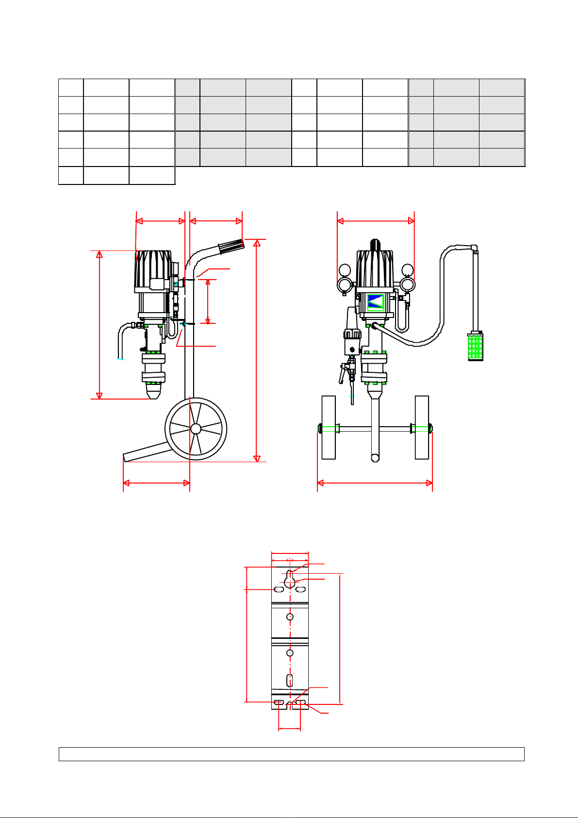
ÂCAUTION : The number of spirals must equally be distributed on
each fastening parts in order to get the above dimension.
Before reassembling the different components :
-Clean the parts with white spirit or with the appropriate cleaning solvent.
-Install new seals if necessary, after having lubricated them with PTFE grease.
-Lubricate the piston and the inside of the cylinder to prevent from damaging the seals.
-Install new parts if necessary.
DEGREES OF WEAR
The wetted parts in contact with the material are subject to wear with time. It depends, of course, on
the rates and duration of pump operating; also on the material handled.
Under normal operating and servicing conditions, with standard filled material not including foreign
matters of chemically agressive, the average working life can be estimated as :
-1 million strokes for the tightness seals.
-10 millions strokes for the bellows .
31.85 mm ±0.5

KREMLIN Page 6 Manual : 573.024.212
ASSEMBLY INSTRUCTIONS
A 1
A 2
A 1
A 1
S 1
A 1
A 1
A 1
S 1
A 2
C 2
A 1
A 1
A 1
Index Instructions Description Part number
PTFE grease "TECHNILUB" grease
(10 ml)
560.440.101
Graphite grease Graphite grease
(100 g)
560.420.005
Low strength - Aneorobic Adhesive
- (Simular as Loctite 222)
Screwing torque 40 Nm / 29.5 ft/ lbf
A 1
A 2
C 2
S 1
Table of contents
Other Kremlin Water Pump manuals
Popular Water Pump manuals by other brands

Graco
Graco Check-Mate P05LCS Instructions and parts

Zipper Mowers
Zipper Mowers ZI-GP1200 Operation manual

Impact Pumps
Impact Pumps SLX-40 user guide

Kessel
Kessel Aqualift F XL Duo Instructions for installation, operation and maintenance

GORMAN-RUPP
GORMAN-RUPP V3A60-B Installation, operation and maintenance manual

Oase
Oase AquaAir 250 operating instructions

Stübbe
Stübbe SP 820 Series operating manual

Pentair
Pentair HYDROMATIC SPX50 Installation and service manual

SurePoint
SurePoint PUMPRIGHT PR17 manual

SOLIDSVAC
SOLIDSVAC SV10-AIR FOX Operation manual

Grundfos
Grundfos AP80 Series Installation and operating instructions

Draper
Draper 87680 Original instructions