Krohn-Hite 1200A User manual

Model 1200A
Linear Sweep/Function Generator
0.2Hz to 3MHz
Serial No. _______________________
Operating Manual
Copyright 2004. All rights re served. Con tents of this pub li ca tion may not be re pro duced in
any form with out the writ ten per mis sion ofKrohn-HiteCorporation.Re vi sion 063004. Printed
in U.S.A.
15 Jonathan Drive, Unit 4, Brockton, MA 02301-5566
Tel: (508) 580-1660; Fax: (508) 583-8989
info@Krohn-hite.com; www.krohn-hite.com


Table of Contents
1.0 GENERAL DESCRIPTION ·························1-1
1.1 INTRODUCTION ································1-1
1.2 SPECIFICATIONS ·······························1-1
1.2.1 Waveforms ...............................1-1
1.2.2 Frequency Range ...........................1-1
1.2.3 Frequency Control ..........................1-2
1.2.4 Frequency Accuracy .........................1-2
1.2.5 Main Output ..............................1-2
1.2.6 Operational Modes ..........................1-3
1.2.7 Sweep Characteristics ........................1-3
1.2.8 External Frequency Control (VC) ................1-3
1.2.9 Variable DC Offset ..........................1-3
1.2.10 TTL Output...............................1-4
1.2.11 Control Voltage (CV) Output ...................1-4
1.2.12 Operating Ambient Temperature Range .............1-4
1.2.13 Controls.................................1-4
1.2.14 Terminals ................................1-4
1.2.15 Power Requirements .........................1-4
1.2.16 Dimensions and Weights . . . . . . . . . . . . . . . .......1-5
1.2.17 Optional Rack Mounting Kit (see Figure 2) ..........1-5
2.0 OPERATION···································2-1
2.1 POWER REQUIREMENTS ··························2-1
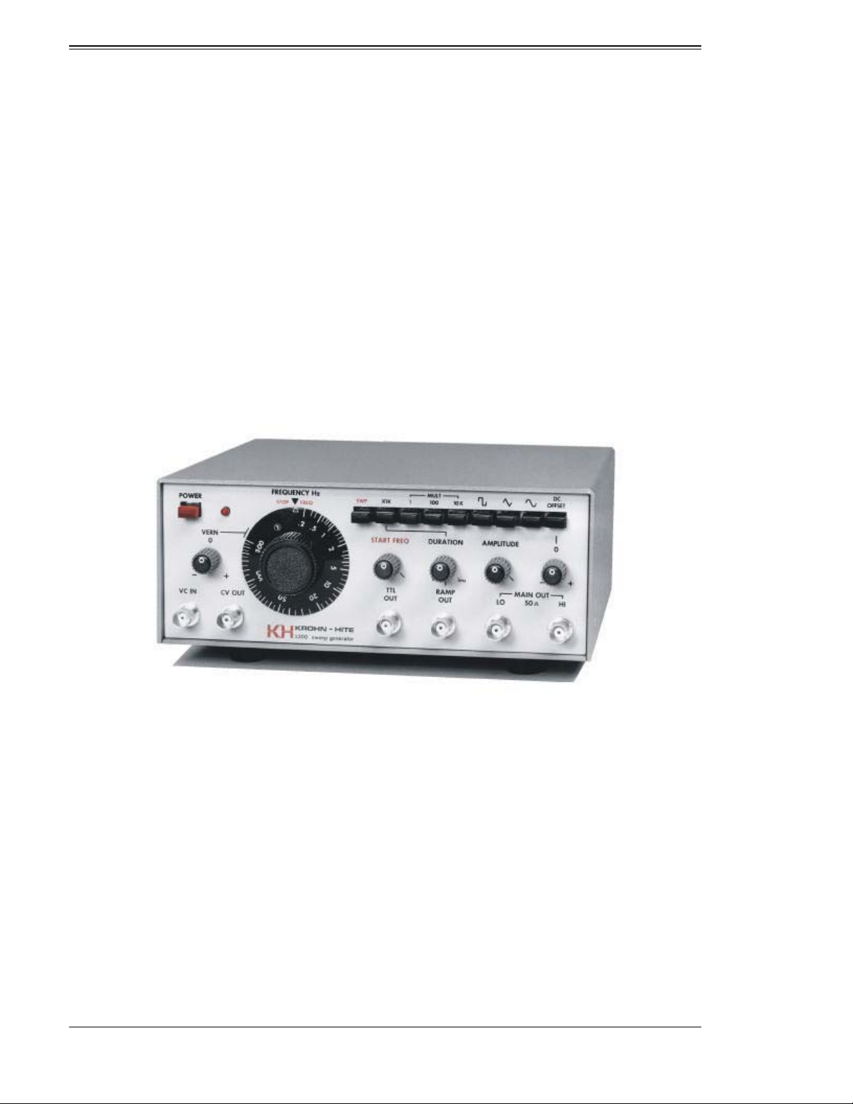
2.2 OPERATING CONTROLS AND CONNECTORS (see Figure 3) · · · 2-3
2.2.1 Front Panel ...............................2-3
2.2.2 Rear Panel ...............................2-4
2.3 OPERATION · · · · · · · · · · · · · · · · · · · · · · · · · · · · · · · · · · · 2-5
2.3.1 Frequency Hz/Stop Freq Dial and Multiplier .........2-5
2.3.2 Internal Sweep Operation. . . . . . . . . . . . . . . .......2-5
2.3.3 External Frequency Control (VC) ................2-6
2.3.4 Variable DC Offset ..........................2-6
2.3.5 Calibrated CV (Control Voltage) Output ............2-6
2.3.6 Waveguard Circuit ..........................2-7
i
Table of Contents

3.0 INCOMING INSPECTION AND CHECKOUT ·············3-1
3.1 INTRODUCTION ································3-1
3.2 EQUIPMENT REQUIRED ··························3-1
3.3 PROCEDURE ··································3-2
3.3.1 Waveforms ...............................3-2
3.3.2 Amplitude Control ..........................3-2
3.3.3 DC Offset................................3-2
3.3.4 Frequency Controls and Accuracy ................3-2
3.3.5 External Voltage Control (VC) ..................3-2
3.3.6 CV Output ...............................3-3
3.3.7 Sweep Operation ...........................3-3
3.3.8 Frequency Response .........................3-3
3.3.9 Sinewave Distortion .........................3-3
3.3.10 TTL Output...............................3-4
ii
Table of Contents

Notes
iii
Notes

iv
Mdeol 1200A Photo
Figure 1. Model 1200A Linear Sweep/Function Generator

Section 1
GENERAL DESCRIPTION
1.1 INTRODUCTION
The Krohn-Hite Model 1200A, il lus trated in Fig ure 1, com bines a func tion gen er a tor and ramp gener-
a tor in one in stru ment. An ex clu sive fea ture of the 1200A is WAVEGUARDä, a unique out put protec-
tion cir cuit that pro tects the gen er a tor’s MAIN (HI) OUT PUT from dam age, if a volt age is acciden-
tally placed across the output termi nals. The WAVEGUARDcir cuitre cov ersau tomat i callywhen the
external voltage isre moved.
The main gen er a tor pro vides sine, tri an gle and square wave forms from 0.2Hz to 3MHz. Fre quency is
con trolled by the tun ing dial, cal i brated in Hertz from .2 to 30 (1500:1) plus a 3 band, de cade multi-
plier. A fine-tune vernier provides ±2.5% adjustment of the dial setting. Frequency may be also con-
trolled externally by an AC or DC voltage ap plied to the ex ter nal volt age con trol (VC) in put.
The aux il iary ramp gen er a tor am pli tude is con tin u ously ad just able from 5mV p-p to 20 volts p-p,
open-circuit. Out put im ped ance is a con stant 50 ohms. A si mul ta neous LO (-20dB) out put is also
provided.
Ad di tional fea tures in clude: ±10V vari able DC off set, aux il iary TTL out put and a cal i brated CV (con-
trol volt age) out put, pro por tional to the main gen er a tor fre quency.
A Rack-Mounting Kit, part No. RK-39, is also available.
The gen er a tor is care fully in spected, aged and ad justed be fore ship ment, and should ready for opera-
tion when it is unpacked. If it appears to have been damaged in ship ment, file a claim with the freight
car rier, and no tify Krohn-Hite or its near est sales of fice im me di ately.
1.2 SPECIFICATIONS
1.2.1 Waveforms
Sine, tri an gle, TTL, ramp.
1.2.2 Frequency Range
0.2Hz to 3MHz.
1-1
Section 1 - General Description

1.2.3 Frequency Control
Single turn dial calibrated logarithmically from 0.2 to 300 in Hertz, and a 3 positionmultiplier pro vid-
ing a 1500:1 coverage in each multiplier position. Sep a rate fine-tune ver nier pro vides 5% adjustment.
BAND MULTIPLIER FREQUENCY RANGE (Hz)
1 1 0.2 – 300
2 100 20 – 30k
3 10K 2k – 3M
1.2.4 Frequency Accuracy
±5% at three dial cal i bra tion set tings of 10, 100 and 300; ±20% max i mum at other set tings.
1.2.5 Main Output
1.2.5.1 Waveforms
Sine, square, triangle.
1.2.5.2 Output
HI LEVEL (0dB): 20 volts p-p open-circuit, 10 volts p-p across 50 ohms.
LO LEVEL (-20dB): 20 volts p-p open-circuit, 1 volt p-p across 50 ohms.
1.2.5.3 Isolation
Can be floated up to ±200 volts peak be tween out put and in stru ment case.
1.2.5.4 Amplitude Stability (Maximum Amplitude)
10 min utes, 0.02%; 24 hours, 0.1%
1.2.5.5 Amplitude Control
Infinite resolution vernier. Minimum output less than 5 millivolts.
1.2.5.6 Frequency Response
Sine wave, less than 0.1dB from 0.2Hz to 300kHz; 1.0dB to 3MHz.
1.2.5.7 Sine Wave Distortion
Less than 0.5% from 2Hz to 300kHz; 3% to 3MHz.
1.2.5.8 Square Wave
Rise and fall time, less than 40ns; to tal abberations less than 5% with 50 ohm ter mi na tion.
1-2
Section 1 - General Description

1.2.5.9 DC Components
All waveforms are normally symmetrical about ground with nom i nal zero DC volts. At max i mum
out put, drift is less than 5 mil li volts per de gree C.
1.2.5.10 Triangle Linearity
Greater than 99% from 0.2Hz to 300kHz; 95% to 3MHz.
1.2.5.11 Time Symmetry
Sine, square, tirangle 99% from 0.2Hz to 300kHz.
1.2.6 Operational Modes
Continu ous orlinear sweep.
1.2.7 Sweep Characteristics
1.2.7.1 Sweep Range:
Maximum 1500:1 up or down; upper and lower limits set by tun ing dial and START FRE QUENCY
control.
1.2.7.2 Sweep Duration
1000s – 1ms in two ranges; 1000s – 1s, 1s – 1ms.
1.2.7.3 Ramp Output
+5V peak sawtooth, frequency adjustable with DURATION control, .002Hz – 1kHz. Ramp retrace,
less than 75ms. Output impedance, constant 600 ohms.
1.2.8 External Frequency Control (VC)
1.2.8.1 Range
1500:1.
1.2.8.2 Voltage Control Range
Zero to ±3volts. (A max i mum of ±25 volts may be ap plied to the VC in put with out dam age to the cir
-
cuitry).
1.2.8.3 Input Impedance
10k ohms.
1.2.9 Variable DC Offset
±10 volts open-cir cuit, ±5 volts across 50 ohms. Push-but ton ON-OFF Con trol with sep a rate vernier.
(Reduced by –20dB on LO output).
1-3
Section 1 - General Description

1.2.10 TTL Output
TTL pulse at generator fre quency, drives up to 10 TTL loads; rise and fall times less than 15ns.
1.2.11 Control Voltage (CV) Output
+2mV to 3 volts, proportional generatorfrequency.
Ac cu racy, better than 5%. Out put im ped ance, 600 ohms.
1.2.12 Operating Ambient Temperature Range
-10°C to 45°C.
1.2.13 Controls
Front panel contains FREQUENCY dial, frequency VERNier, STARTFRE Quency,DU RATION,
AM PLI TUDE, DC OFF SET and push-but ton con trols for fre quency range MUL Ti plier, MAIN OUT-
put wave form se lec tor, SWP on, sweep range mul ti plier, and POWER switch. Rear panel con tains
LINE switches, SYMmetry ADJust, DC LEVEL AD Just ment and GROUND switch.
1.2.14 Terminals
Front panel only, BNC con nec tors for HI and LO out puts, TTL out put, CV out put, RAMP out put, and
VC input.
1.2.15 Power Requirements
Switch selectable, 90-110, 108-132, 180-220, or 216-264 volts, sin gle phase, 50-400Hz, 13 watts.
1-4
Section 1 - General Description

1.2.16 Dimensions and Weights
Cabinet Size/Weight H W D Net Gross
U.S. 3-1/2” 9” 8-1/2” 5 lb. 7 lb.
Metric 9cm 23cm 21.7cm 2.3kg 3.2kg
1.2.17 Optional Rack Mounting Kit (see Figure 2)
Part No. RK-39; permits in stal la tion of the Model 1200A into a stan dard, 19” rack spac ing.
Figure 2. Optional Rack Mounting Kit
Specifications ap ply at 25°C, ±5°C at max i mum out put volt age, and dial set be tween 2 and 300, unless
otherwise noted.
Specifications sub ject to change with out no tice.
1-5
Section 1 - General Description

This page intentionally left blank.
1-6
Section 1 - General Description

Section 2
OPERATION
2.1 POWER REQUIREMENTS
The Model 1200A is de signed to op er ate from a sin gle phase, 50-400Hz AC power source of 90-110,
108-132, 180-220 or 216-264 volts. Complementary LINE switches on the rear panel allow the
1200A to be pow ered from one of the above 4 voltage ranges. The AC power receptacle located on
the rear panel, is a stan dard 3-pin con nec tor. A de tach able 3 wire line cord is pro vided with the instru-
ment.
The fuse re cep ta cle con tains ei ther a 1/8 am pere slow blow fuse (90-132 volt op er a tion) or a 1/16 am-
pere slow blow fuse (180-264 volt operation).
To turn the instrument on; a) set the LINE switches for the correct AC line voltage range; b) check for
or in sert the prop erly rated fuse into the fuse re cep ta cle and se cure; c) make sure the front panel
POWER switch is off (out) before you connect the line cord to the AC power source; d) depress the
POWER switch and allow the generator to warm up for several minutes.
2-1
Section 2 - Operation

Figure 3. Operating Controls and Connectors
2-2
Section 2 - Operation

CAUTION!
The cover of this in stru ment should not be re moved when the in stru ment is con nected to an AC
power source, be cause of the po ten tially dan ger ous volt ages that ex ist within the unit.
2.2 OPERATING CONTROLS AND CONNECTORS (see Figure 3)
2.2.1 Front Panel
2.2.1.1 Power:
Push-button ON-OFF switch and power ON indicator light.
2.2.1.2 Frequency:
Hz/STOP FREQ: Single turn dial, calibrated in Hertz from .2 to 300, with a separate, fine-tune VER-
Nier, plus a 3 po si tion, push-but ton MUL Ti plier switch, X1, X100 and X10K. Ef fec tive dial turning
range 1500:1. The out put fre quency is the dial set ting, in Hz, times the MUL Ti plier set ting, with the
VERNier in its (0) position. In the sweep mode of op er a tion the DIAL and MUL Ti plier de termine the
sweep fre quency STOP limit, while the START FREQ con trol de ter mines the start of the sweep fre-
quency.
2.2.1.3 SWP:
Push-button switch that converts the generator to con tin u ous sweep op er a tion. When the SWPbut ton
is depressed the frequency sweep will al ways be gin at the START FREQ set ting.
2.2.1.4 Start Freq:
Single turn po ten ti om e ter for ad just ing the start of the fre quency sweep.
2.2.1.5 Duration:
Single turn potentiometerthat de ter mines the weep du ra tion (rate). Sweep du ra tion is continuously ad-
justable from 1000 seconds to 1 second, or 1 secondto1milli sec ond.
2.2.1.6 X1K:
Push-button con trol that se lects a sweep du ra tion range of (du ra tion) 1000s – 1s (de pressed) or 1s –
1ms (out).
2.2.1.7 Waveform:
3 posi tion, push-but ton switch for se lect ing sine, square and tri an gle out put wave forms.
2.2.1.8 Amplitude:
Single turn, in fi nite res o lu tion con trol for ad just ment of he out put am pli tude from 5mV p-p to 20 volts
p-p, open circuit.
2-3
Section 2 - Operation

2.2.1.9 DC Offset:
Push-button ON-OFF switch, plus sep a rate sin gle turn ver nier, for off set ting the DC level of the out-
put wave form be tween ±10 volts, open-cir cuit. The com bined DC off set plus AC sig nal should not
exceed ±10 volts, open-circuit, or clip ping of the wave form may oc cur.
2.2.1.10 Main Out:
HI - The se lected wave form ap pears at this out put.
Impedance, 50 ohms.
LO - The selected wave form ap pears at this out put, at ten u ated by –20dB with re spect to the HI out put.
Impedance, 50 ohms.
2.2.1.11 VC In:
Provides for external volt age con trol of fre quency. A max i mum con trol volt age of zero to 3 volts will
vary the gen er a tor fre quency to the max i mum range of 1500:1. In put im ped ance, 10k ohms.
2.2.1.12 CV Out:
DC volt age, pro por tional to the dial fre quency set ting, +2mV to +3 volts. In SWP mode, used in con
-
junction with START FREQ con trol to set the start ing point of the fre quency sweep. Out put imped-
ance, 600 ohms.
2.2.1.13 TTL Out:
TTL pulse, coincident with generator fre quency, in phase with the main out put square wave. Will
drive up to 10 TTL loads. Rise and fall times, less than 15ns.
2.2.1.14 Ramp Out:
Fixed zero to +5 volt lin ear ramp, rate co in ci dent with sweep DU RA TION con trol. Ramp re trace, less
than 75ms. Out put im ped ance, 600 ohms.
2.2.2 Rear Panel
2.2.2.1 Line:
Complimentary slide switches for selecting 120 or 240 volt operation, and NORMal or Low line con-
di tions. The 120/240V LINE switch de ter mine the proper volt age range (90-132V or 180-264V)
while the NORM/LO LINE switch selects NORMal (108-132, 216-264) or Low (90-110, 180-220)
linevolt age.
2.2.2.2 SYM ADJ:
Potentiometerfor periodicadjustmentofthewaveformsymmetry.
2.2.2.3 DC Output Level:
Potentiometerfor pe ri odic ad just ment of the MAIN OUT PUT DC.
2-4
Section 2 - Operation

2.3 OPERATION
2.3.1 Frequency Hz/Stop Freq Dial and Multiplier
The gen er a tor fre quency is con trolled by the main tun ing (FRE QUENCY Hz/STOP FREQ) dial and
MULTiplier. The tun ing dial is cal i brated in Hertz, from 0.2 to 300, for an over all tun ing rage of
1:1500. The 3 position, push-button MUL Ti plier mul ti plies the dial set ting by a fac tor of 1, 100, or
10K (10,000). A separate, sin gle-turn VER Nier pro vides ad di tional fine ad just ment of ±2.5% of the
dial set ting. With the VER Nier in the cal i brated (0) po si tion, the gen er a tor fre quency is the dial set-
ting, in Hertz times the MULTiplier.
When the gen er a tor is used in the SWP mode, the FRE QUENCY dial de ter mines the stop ping point of
the frequency sweep.
2.3.2 Internal Sweep Operation
When the front panel SWP button is de pressedthegen er ator fre quencywill contin u ouslysweep be-
tween the lim its set by the START FREQ control and the FREQUENCY Hz/STOP FREQ dial, at a
rate de ter mined by the SWP DU RA TION con trol. The gen er a tor fre quency may be ei ther swept up or
down, up to a max i mum of 1500:1, over the cal i brated por tion of the tun ing dial. To op er ate the
Model 1200A as a sweep generatorproceed as follows:
1) Depress the SWP-on button.
2) Se lect the fre quency range within which you wish to sweep by se lect ing the ap pro pri ate frequency
MULTiplier range.
SWEEP RANGE MULTiplier
0.2Hz-300Hz X1
20Hz-30kHz X100
2kHz-3MHz X10k
3) Set the FREQUENCY Hz/STOP FREQ dial to the beginning (start) fre quency of the de sired
sweep range.
4) Connect an os cil lo scope to the MAIN OUT con nec tor and ad just the START FREQ con trol un til
the fre quency stops sweep ing. This sets the start fre quency at the dial set ting.
5) Tune the FREQUENCY Hz/STOP FREQ dial to where you want the fre quency sweep to stop.
Once the start fre quency is set by the START FREQ con trol, the stop fre quency can be var ied over
any por tion of the FRE QUENCY dial, with out af fect ing the start fre quency. The gen er a tor frequency
will sweep lin early over the lim its set by the START FREQ con trol and STOP FREQ dial.
To set the sweep duration, con nect a coun ter to the RAMP OUT and ad just the DU RA TION con trol to
the desired sweep rate. The DURATION con trol is a sin gle turn po ten ti om e ter that will adjust the
sweep du ra tion con tin u ously from 1 sec ond to 1 mil li sec ond. When the DU RA TION X1K mul tiplier
is in the re cessed po si tion, the sweep du ra tion range will be mul ti plied by a fac tor of 1,000 (1k). The
sweep du ra tion will then cover a range of 1000 sec onds to 1 sec ond.
When the gen er a tor is used in the non-sweep mode, the RAMP OUT, con sist ing of a fixed, zero to
+5V lin ear ramp, may be used in de pend ently of the main gen er a tor, with fre quency con trolled by the
DURATIONcontrol.
2-5
Section 2 - Operation

2.3.3 External Frequency Control (VC)
The gen er a tor fre quency may also be con trolled by an ex ter nal volt age ap plied to the VC (voltage
control) input. A maximum control volt age of zero to 3 volts will vary the gen er a tor frequency up to a
ra tio of 1500:1 within the range of the tuning dial. The VC voltage will vary the frequency as the ra-
tio of:
ΔFHz
Volt MULTiplier VC Voltage=× ×−
100
The VC con trol is used as fol lows:
1) With the FRE QUENCY dial set to it low (.2) end, a zero to pos i tive-go ing ramp volt age ap plied to the
VC input will sweep the generator fre quency up wards, by as much as 1:1500.
2) If the dial is set to its high (300) end, and a zero to neg a tive-go ing ramp volt age is ap plied,thegenerator
fre quency will be swept down by 1500:1.
3) A sinusoidalwaveform ap plied to the VC in put will mod u late (FM) the main out put fre quency about
the dial setting.
Asafurtherexampleof(3)above,sup pose you wish tomodulatethegeneratorfrequency± 20% of the dial
setting. Let us select arbitrary numbers, e.g., dial set at 10kHz (100 x 100), frequency of modulation,
10Hz. From the frequency to VC voltage expression,
Given: ΔFHz
Volts MULTiplier VCVoltage=× ×
100
Where: ΔFkHzkHz=± × =±20 10 2%
Therefore, VC Voltage = ΔF
MULTipleir
Volt
Hz
Hz Volt
Hz
×
=±× ×
×
=
1
100
0 2 103 1
100 100
.
±02.Volts
A sinusoidal voltage of ±.2 volts at a rate of 10Hz is required.
2-6
Section 2 - Operation

2.3.4 Variable DC Offset
The vari able DC OFF SET Con trol con sist of a push-but ton ON-OFF switch plus a sin gle turn po tenti-
ometer. It is used to vary the DC level of the output wave-form. The OFFSET potentiometer will
vary this level from mi nus (-) 0 volts to plus (+) 10 volts. The combined peak AC plus DC offset
should not ex ceed ±10 volts peak, oth er wise clip ping of the wave form may oc cur.
2.3.5 Calibrated CV (Control Voltage) Output
The cal i brated, CV out put is a DC volt age pro por tional to the FRE QUENCY dial set ting, and covers a
range of +2 mil li volts to +3 volts. The CV out put volt age is ac cu rate to
within 5% of the generator’s out put fre quency, over the cal i brated range of the dial. It may be con-
nected to a dig i tal volt me ter for mon i tor ing of fre quency, or it may be used to drive an x-y plotter.
Output impedance is 600 ohms.
It may also be used as an independent ramp out put in the SWP mode; its start level and peak ampli-
tude are con trolled by the gen er a tor’s START FREQ and FRE QUENCY Hz/STOP FREQ con trols, re-
spectively.
2.3.6 Waveguard Circuit
The ex clu sive WAVEGUARD out put pro tec tion cir cuit is con nected across the gen er a tor’s HI output
ter mi nals. The cir cuit pre vents dam age to the gen er a tor’s out put am pli fier stage, if a volt agegreater
than ±12 volts is accidentally placed across the HI outputterminal.
WARNING!
When the WAVEGUARD cir cuit is ac ti vated, it will short-cir cuit the ap plied volt age to ground.
A low-ohm resistor is in ter ested in se ries with the WAVEGUARD cir cuit and the HI out put terminal, to
protecttheWAVEGUARDcircuitfromexceedingitsmaximum,continuous,continuouscurrentrating.
Alow frequencies, thecircuit willrecover automat icallywhen theexter nalvoltage isre moved; at higher
fre quen cies, it may be nec es sary to turn the am pli tude down or shut the power off mo men tarily to re set the
cir cuit af ter the ex ter nal volt age is re moved.
2-7
Section 2 - Operation

This page intentionally left blank.
2-8
Section 2 - Operation
Table of contents
Other Krohn-Hite Portable Generator manuals
Popular Portable Generator manuals by other brands

Parker
Parker N2-120 Installation, operation & maintenance manual

Danfoss
Danfoss EM-PMI540-T4000 user guide

Escort
Escort EGC-3236A user manual

Krüger Technology
Krüger Technology KGVG4001 instruction manual

Abestorm
Abestorm OZ-G1000 user manual

Generac Power Systems
Generac Power Systems 45kW owner's manual