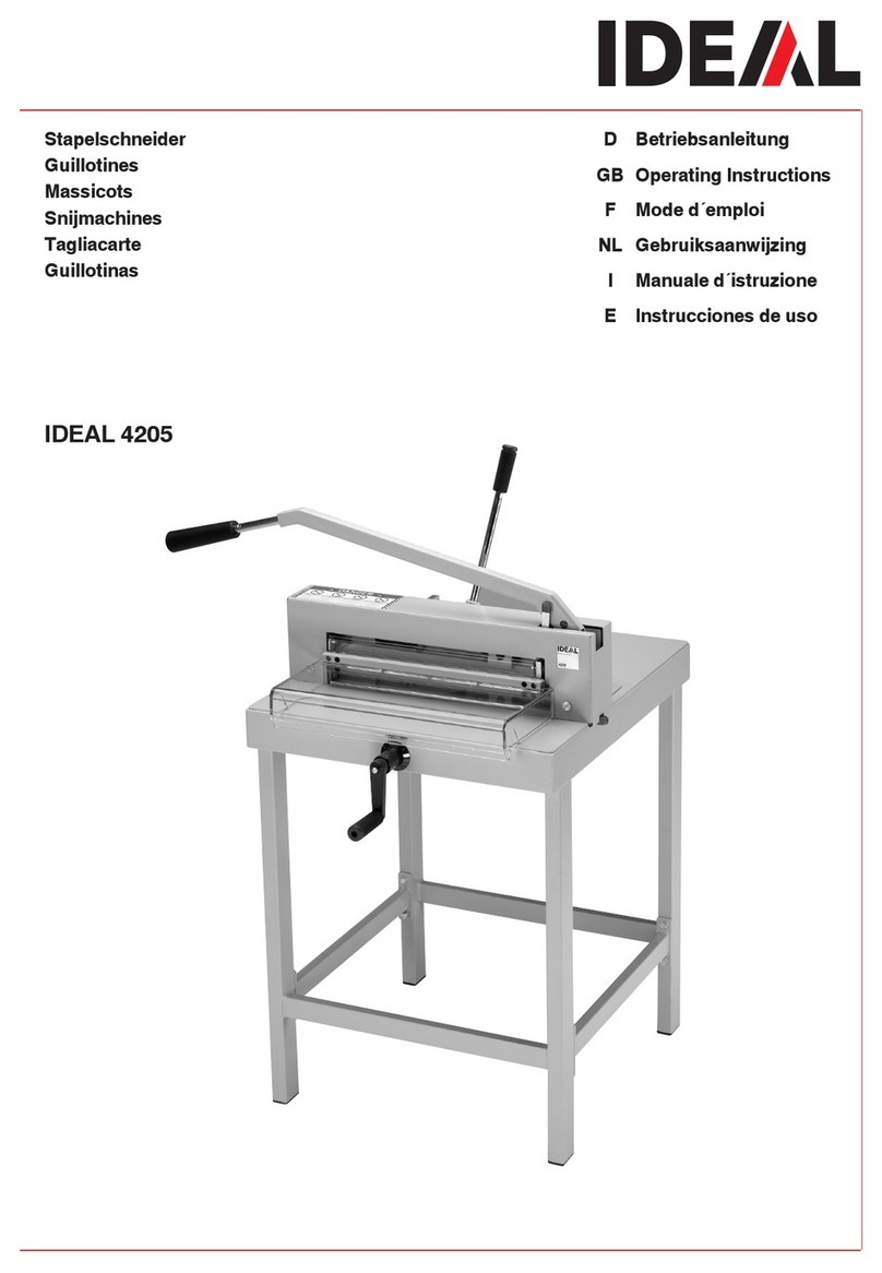
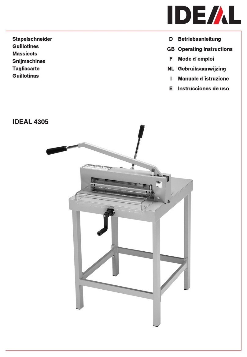
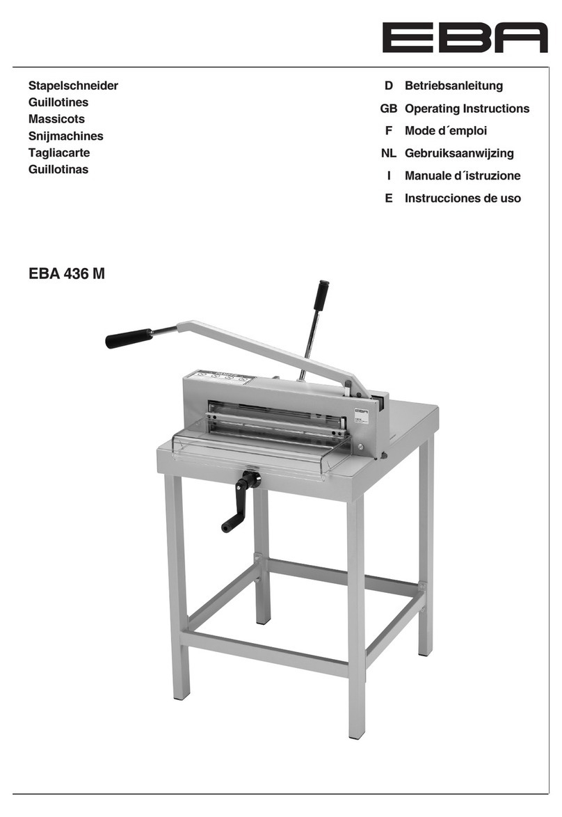
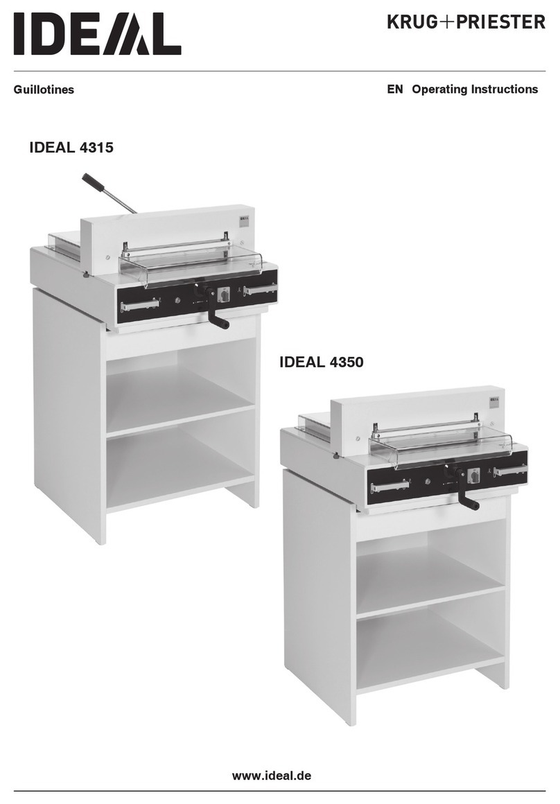
Krug & Priester EBA 4315 User manual

EN Operating Instructions
Guillotines
www.eba.de
EBA 4350
EBA 4315

- 2 -
Table of Contents
Safety precautions 3
Intended use 4
Installation 10
Startup 12
Operation 14
Operating elements 19
Blade and cutting stick replacement 22
Maintenance and cleaning 31
Annual inspection / Safety test 31
Possible malfunctions 33
Accessories 37
Technical data 38
EC-declaration of conformity 41

- 3 -
Safety precautions
Please read these operating instructions before putting the machine into
operation and observe the safety precautions.
The operating instructions must always be available.
Children must not operate the machine!
Do not reach beneath the blade!
Never leave the blade unattended!
Do not extract or transport the blade without
protection! (See page 24 and 26).
Danger! Risk of injury!
Do not cut hard materials or materials which
may splinter!

- 4 -
Intended use
The machine is designed for cutting stacks of
paper to a specied size.
This machine is constructed for "one-man
operation" only!
Warning! Clips or similar damage the
cutting blade.
Safety precautions / Intended use
Do not use any spray cans with flammable
content near to the cutting machine!
Do not use any flammable cleaning agents.

- 5 -
Disconnect from the mains before starting any
service work or before removing the panels!
Replacement of blade and cutting stick may
be performed only when the main switch is
switched off!
Safety precautions

- 6 -
A
A
A
B
C
A
C
All components which could endanger the
operator are covered by a guard!
Operating the machine without safety device is
forbidden!
•Movable front safety guard (A)
•rear screwed safety guard (B)
•and cover (C)
Safety precautions

- 7 -
B
C
A
The dangerous cutting movement is
safeguarded by a movable guard (A), rear
screwed safety guard (B) and a safety
two-handed control system! (C)
Before working with the machine and after
every blade replacement the automatic cut-off
function of safety guard (A),(correct if distance
between cover and table is < 15 mm) main
switch (B) and control panel (C) must be
checked.
Safety precautions

- 8 -
230 V / 10A min
120 V / 15A min
Protect mains cable against heat, oil and
sharp edges!
Connect the power cord to a single phase
socket.
Ensure free access to mains
Safety precautions

- 9 -
When not in use for a longer period switch
off (Main switch to "0").
Clamping Blade
OK
OK
Danger!
Do not turn main switch to position "0"
whilst blade is moving upwards or
downwards!
Risk of injury!
Danger! Blade must always be covered
by the pressing bar.
Safety precautions

- 10 -
B
A
A
B
Unpack the cabinet (A), (accessories) or
stand (B), (accessories) and assemble
according to the enclosed separate
instructions.
2 strong people are required to lift the
machine onto the cabinet. Beware of ngers!
Do not hold onto the actuators (B) when
lifting the machine out of the packaging!
The operating side of the machine must
align with the cabinet (A)!
Risk of injury!
Installation

- 11 -
Assembly of stand:
2 strong people are required to lift the
machine out of the packaging.
• Lay the machine on the oor side
wards (1.).
•Remove the lower cover (2.)
•Place the cutter correctly onto the machine
stand. Fit the 4 washers and tighten the
4 hexagon nuts with a spanner (3.).
•Screw on the lower cover (4.)
•Install the machine.
Installation

- 12 -
Startup
Plug into socket.
Screw on the backgauge crank (A).
Screw on the handle (B) (only 4315)
found in the tool set (C).
Installation / Startup

- 13 -
B
B
A
A
A
It is forbidden to operate the machine if the
operating and safety instructions have not been
understood. Please check the safety devices
are functioning and complete before use.
•All covers have to be mounted (A).
•The release for cutting is allowed only if
the cover is closed and the two-hand
safety device is operated at the same time (B).
•The front cover should not close by
itself. Tighten the hexagonal recess
screw right (C).
We recommend you keep a record of your test
results.
Startup

- 14 -
B
A
C
Position the main switch "I" (A) Insert
the key the control system and move
it to the right (B). Open the safety guard (C).
The machine is now ready for use.
Operation

- 15 -
A
B
C
D
E
The measurement is set with the backgauge
crank.(A) The symbol – rotary direction –
moves to the right on the display (B)
(see picture C). The rotary direction of the
backgauge crank (A) is indicated on the right.
Keep turning the backgauge crank to the right
until a measurement appears (see picture E).
The reference position is reached.
The cutting size can now be set with the
handle (A).
If the backgauge is right at the front the
symbol – rotary direction – will move to the
left (see picture D). Turn the backgauge crank
to the left until the rotary direction appears on
the right in the display (see picture C).
Afterwards turn the backgauge crank to the
right until a measurements appears (see
picture E). The reference position is reached.
The cutting size can now be set with the
handle (A). Proceed to position from the
rear.
Measurement is shown on the display in inches
or cm (B).
Information:
When the machine is only switched off by the
Key switch G(main switch Eis still ON) it is
not necessary to advance to the reference
point when a new measurement is inserted.
Operation

- 16 -
Optical cutting red line (A). Blade cuts on the
front edge (B) of the light beam.
(Only use when no exact cut is required).
Pull out the handle to avoid the measurement
being wrongly adjusted.
Operation

- 17 -
BC
A
Position the paper on the backgauge (A) and
the side lay (B). To move paper stacks,
please use the paper knock-up block (C).
Run backgauge to the front for turning the
paper stack.
Close the safety guard.
Operation

- 18 -
A
A
Cutting activation:
Press both buttons of the two-handed control
system (A) simultaneously and keep them
pressed until the paper is completely cut.
To interrupt or stop cutting:
To interrupt or stop cutting, release
both buttons (A) of the two-hand control.
4315
Before every cut the lever must be moved to
the left and tightened with light pressure.
4350
The clamp moves automatically when cutting
is activated.
Operation

- 19 -
Operating elements
A- Front safety guard
B- Safety two-handed control system
C- Overload switch blade drive
D- Clamping
E- Main switch
F- Crank handle for backgauge setting
G- Key switch
H- Backgauge
I- Side lay left
J - Display cutting size (cm or inch)
K- Changeover cm/inch
L - Measuring unit (cm or inch)
Operation / Operating elements

- 20 -
A
B
C
D
E
Start machine
•Main switch Eto position "I", insert the key
G for the control panel and turn it to the right.
Open the front safety guard A.
Warning!
Before cutting a measurement please check if
the correct scale (cm or inch) is set.
Display in cm or inch
•Press qKDisplay changes between cm
and inch. For information on how to store see
page 19, picture below left.
•The measurement is set with the backgauge
crank.(A) The symbol – rotary direction –
moves to the right on the display (B) (see
picture C). The rotary direction of the
backgauge crank (A) is indicated on the right.
Keep turning the backgauge crank to the right
until a measurement appears (see picture E).
The reference position is reached. The
cutting size can now be set with the
handle (A).
If the backgauge is right at the front the
symbol – rotary direction – will move to
the left (see picture D). Turn the backgauge
crank to the left until the rotary direction ap-
pears on the right in the display (see
picture C). Afterwards turn the backgauge
crank to the right until a measurements
appears (see picture E). The reference
position is reached. The cutting size can now
be set with the handle (A). Proceed to
position from the rear.
The measurement scale in cm or inch has a
LED display L.
For information on how to store see page 19,
picture below left.
Operation
This manual suits for next models
1
Table of contents
Other Krug & Priester Cutter manuals