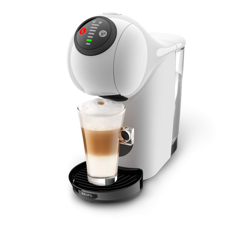
Krups Nescafe Dolce Gusto Lumio KP130110 User manual

SERVICE MANUAL
BEVERAGE CENTER
LUMIO
1/ Version 1.1 en
28.09.2017

Lumio service manual
2
CONTENTS
Main components.................................................................................................. 6
Overview of external parts............................................................................................ 6
Overview of internal parts............................................................................................. 7
Overview of extraction head parts................................................................................ 9
Rating plate ................................................................................................................. 11
Breville rating plate (example)................................................................................ 12
Water circuit................................................................................................................ 13
Schematic diagram................................................................................................. 13
Circulation model.................................................................................................... 14
Technical data ............................................................................................................ 15
Operating................................................................................................................ 19
Machine status ........................................................................................................... 19
HMI module ................................................................................................................ 20
Basic operation........................................................................................................... 20
Switch on coffee machine ...................................................................................... 20
Eco mode ............................................................................................................... 21
Preparation for first use .............................................................................................. 22
Preparing a beverage................................................................................................. 24
Special precaution to prevent water splashes............................................................ 25
Empty fluid system for shipping.................................................................................. 26
Troubleshooting................................................................................................... 27
Read error code ......................................................................................................... 27
Error code list ............................................................................................................. 28
Troubleshooting checklist ........................................................................................... 29
Repair....................................................................................................................... 34
General....................................................................................................................... 34
Safety information ...................................................................................................... 34
Basic repair instructions ............................................................................................. 34
Tools and repair accessories...................................................................................... 35
Screw tightening torques............................................................................................ 36
Simple repair work...................................................................................................... 37
Disassembly preparations .......................................................................................... 38
Remove and replace bottom parts ............................................................................. 39
Remove base cover ............................................................................................... 39
Assembly tips ......................................................................................................... 40
Remove bottom part............................................................................................... 41
Replace flow meter................................................................................................. 42
Assembly tips ......................................................................................................... 44
Replace pump ........................................................................................................ 45
Assembly tips ......................................................................................................... 48
Replace NTC temperature sensor.......................................................................... 49
Assembly tip ........................................................................................................... 49
Replace building block ........................................................................................... 50
Assembly tips ......................................................................................................... 51

Lumio service manual 3
Replace power cord ................................................................................................53
Assembly tips..........................................................................................................54
Replace water tank connector with filter .................................................................55
Assembly tip............................................................................................................56
Remove and replace top parts .................................................................................... 57
Remove HMI module ..............................................................................................57
Remove housing back ............................................................................................58
Assembly tips..........................................................................................................58
Remove housing left and right ................................................................................59
Assembly tip............................................................................................................61
Replace HMI module ..............................................................................................62
Assembly tips..........................................................................................................63
Replace head magnet.............................................................................................64
Replace clamp handle ............................................................................................65
Assembly tip............................................................................................................65
Replace extraction head .........................................................................................66
Assembly instructions and tips................................................................................67
Wiring diagram (EU/USA/Japan)....................................................................69
Final tests................................................................................................................70
Test equipment............................................................................................................ 70
Heating up time........................................................................................................... 71
Priming of fluid system ................................................................................................ 71
Pressure test / flow rate (at 8 bar) / water temperature............................................... 72
Leakage check............................................................................................................ 76
Leakage check for extraction head .........................................................................76
Leakage check for bottom part ...............................................................................79
Final inspections..................................................................................................82
General ....................................................................................................................... 82
Safety instructions....................................................................................................... 83
Protective earthing (PE) resistance test...................................................................... 83
Insulation resistance test............................................................................................. 84
Earth leakage current test ........................................................................................... 86
Maintenance...........................................................................................................87
Cleaning ...................................................................................................................... 87
Clean capsule holder ..............................................................................................87
Deblock injector ......................................................................................................88
Descaling .................................................................................................................... 89
Descaling procedure ...............................................................................................90
Clean machine ........................................................................................................93
Packing instructions .................................................................................................... 95
Spare parts .............................................................................................................97
Spare parts drawing .................................................................................................... 97
Spare parts list .......................................................................................................... 101
Annex......................................................................................................................103
HMI assembly (part no. 9110431700) ....................................................................... 103
Extraction head assembly (part no. 9110431600)..................................................... 104
Lumio service manual
4
Capsule holder assembly (part no. 9110420000)..................................................... 105
Housing right (part no. 3011449200/red, 3011440200/white, 3011449100/black) ... 106
Housing left (part no. 3011449400/red, 3011440300/white, 301144933/black)........ 107
Housing back (part no. 3011440400) ....................................................................... 108
Support frame (part no. 3011440000) ...................................................................... 109
Main frame (part no. 3011447400) ............................................................................ 110
Component frame (part no. 3011447700) ................................................................. 111
Bottom part (part no. 3011447500) ........................................................................... 112
Base cover (part no. 3011450200/red, 3011447600/white, 3011450100/white)........ 113
Drip grid (part no. 3011447900 + 301147640079)..................................................... 114
Drip tray (part no. 3011447800) ................................................................................ 115
Water tank (part no. 9110419400)............................................................................. 116
Building block assembly (part no. 9110434600/110V, 9110420600/220V)................ 117
Locking handle (part no. 3011449700)...................................................................... 118
Pump assembly (part no. 9110434800/110V, 9110429900/220V)............................. 119
Water tank connector tube (part no. 5040127700)................................................... 120
Silicone elbow (part no. 5040127800)...................................................................... 121
Flow meter assembly (part no. 9110420400) ........................................................... 122
Metal sheet (part no. 4030126500) .......................................................................... 123
Flow measurement capsule for final tests ................................................................ 124
Notes ...................................................................................................................... 125

Lumio service manual 5
PREFACE
The purpose of this Service Manual is to provide the service personnel with all neces-
sary information with regards to correct handling, maintenance and repair of the Lumio
beverage center.
This Service Manual should be used by the technicians as a valuable aid to guarantee
the permanent readiness for use of the machine. In order to take full advantage of all the
functions, it is absolutely necessary to follow the instructions in this manual.
If you have any questions, please contact your country’s Nestlé hot line, listed in the user
manual.
For a quick information access, this service manual is also available in the internet as a
PDF or HTML file.
Service manual updates
Version 0.1
• Preliminary service manual version for proofreading.
Version 1.0
• First released service manual version.
Please keep this
manual together
with the corresponding
service documentation.
This way you are assured
to have the necessary
information.
If you display the
service manual on a
computer you can click
on the contents or on
page references to jump
to the required informa-
tion immediately.

Lumio service manual
6
MAIN COMPONENTS
MAIN COMPONENTS
Overview of external parts
The numbers are
not consistent with
the position numbers of
the spare parts list.
1. Water tank
2. Locking handle
3. Selection lever
4. Cold water position
5. Stop position
6. Hot water position
7. Selector wheel for volume
8. Indicator light
9. XL volume function
10. Bar display for filling quantity
11. Capsule holder
12. Injector
13. Rinsing tool
14. Drip grid
15. Drip tray
16. Cleaning needle (not assembled in
Japan)
1
16 15 14
378 10 12 13
911
456
STOP
2

Lumio service manual 7
MAIN COMPONENTS
Overview of internal parts
Sectional view from
the back.
3
1
2
11
4
5
10
6
9 8 7
The numbers are
not consistent with
the position numbers of
the spare parts list.
1. Valve switch
2. Cold water pressure hose
3. Water tank connector
4. Pump
5. Silicone elbow
6. Ferrite core for power cord
7. Power PCB
8. NTC temperature sensor
9. Thermoblock
10. Flow meter
11. Hot water pressure hose

Lumio service manual
8
MAIN COMPONENTS
Building block
Thermoblock (2) and building block PCB (5) are soldered together and cannot be
replaced separately.
1. Building block support
2. Thermoblock
3. Protective ground terminal
4. Thermofuses (2x) with fuse sheet
5. Building block PCB
6. NTC temperature sensor
7. Building block PCB cover
8. Hot water outlet
9. NTC connector
10. Building block connector 2
11. Building block connector 1
12. Flow meter connector
13. Cold water inlet
14. Pump terminal (N)
14
13
8
12 11 10 9
1
2
3
5
7
4
6

Lumio service manual 9
MAIN COMPONENTS
Overview of extraction head parts
The head magnet (5) holds the selection lever in position during the beverage prepara-
tion.
The reed sensor (4) detects if the capsule holder is inserted in the extraction head.
The HMI (Human Machine Interface) module (8) has the following operating and display
elements:
• Selector wheel
• Indicator light
• Bar display
The numbers are
not consistent with
the position numbers of
the spare parts list.
1. Connection hose to water outlet on
extraction head
2. F connector
3. Handle lock lever
4. Reed sensor
5. Head magnet
6. Magnet sheet
7. Left clamp handle
8. HMI PCB / module
8
1
3
7
6
5
2
4

Lumio service manual
10
MAIN COMPONENTS
Capsule holder
The enclosed capsule holder system is designed to
- withstand the maximal pump pressure
- prevent the capsule from delaminating
- protect the user in case of a capsule failure or misuse (hot fluid splashes)
- prevent water from flowing back into the machine
- protect the underside of the extraction head from pollution.
The overflow basin (5) in the capsule holder (4) collects liquid in case of a capsule failure
(blocked capsule) or residual fluid after an extraction.
1. Lid
2. Sealing rubber (bonded to lid)
3. Steel needle
4. Capsule holder
5. Overflow basin
6. Lid lever
7. Spring for lid lever
8. Steel axis
9. Spring right
10. Steel axis left / right
11. Magnet
12. Needle piston
13. Needle valve ball (check valve)
4
6
5
7
8
9
11
2
13 3
10
12
1

Lumio service manual 11
MAIN COMPONENTS
Rating plate
The two-part rating plate is laser engraved on the bottom of the coffee machine.
View from below.
REF: KP130110 /7Z0- WWYY
www.krups.com
MADE IN CHINA
TYPE KP130
220-240V~ 50/60Hz
1340-1600W
Do not immerse in water
xxxxxxxxx
Groupe SEB –53104 Mayenne
France
Explanation of the
rating plate - left
part.
Trade reference
XX = Commercial variant/plug version
CH = SEV plug / 10 = VDE plug / 40 = UK plug
Trade reference
WWYY = Fabrication date
WW = Week / YY = Year
Technical variant
Fabrication origin code
Internet presence
Origin variant
REF: KP130110 /7Z0- WWYY
www.krups.com
MADE IN CHINA
220-240V~ 50/60Hz
1340-1600W
Do not immerse in water
Voltage range, mains frequency, power rating
Warning
Place of manufacture
Only if RoHS (Restriction of Hazardous
Substances) compliant

Lumio service manual
12
MAIN COMPONENTS
Breville rating plate (example)
Explanation of the
rating plate - right
part.
Trade reference
Company address
Eurasian conformity mark
Data matrix code
Special disposal icon (do not dispose with
ordinary waste)
TYPE KP130
Groupe SEB –53104 Mayenne
France
Bar code reference
CCCCCC = Serial number: 0 - 999999
X = Colour code: 1 = white & black,
5 = metal red & black, B = dark silver & black
Y = Country: 0 = EU, 1 = CH / SEV, 2 = UK,
3 = US, 4 = Brazil, 5 = Chile, 6 = Argentina,
7 = HK, 8 = Korea, J = Japan, M = Mexico,
T = Taiwan, S = Singapore & Malaysia,
P = Philippines
Z = Pump type: D = Defond, U = Ulka
CCCCCCXYZ
Approval sign for European Union

Lumio service manual 13
MAIN COMPONENTS
Water circuit
Schematic diagram
The numbers are
not consistent with
the position numbers of
the spare parts list.
1. Water tank
2. Water tank connector with valve
3. Flow meter
4. Pump
5. Thermoblock
6. Selection lever
7. Cold water valve
8. Hot water valve
9. Capsule holder
10. Water connector
11. Check valve
12. Injector
1
2
3
5
7
12
10
9
4
8
6
11

Lumio service manual
14
MAIN COMPONENTS
Circulation model
The numbers are
consistent with the
schematic diagram.
1. Water tank
2. Water tank connector with valve
3. Flow meter
4. Pump
5. Thermoblock
6. Selection lever
7. Cold water pressure tube
8. Hot water pressure tube
9. Capsule holder
10. Water connector
11. Check valve (not visible)
12. Injector (not visible)
10
4
9
5
3
2
1
6
8
7
11, 12

Lumio service manual 15
MAIN COMPONENTS
Technical data
Mains voltages
Europe (LT, EE, LV, RU, NO, SE, FI, DK, ES, IT, CH, UK, DE, AUS, ZA) ..... 230 V, 50 Hz
US / CA ...................................................................................................... 120 V, 60 Hz
Mexico................................................................................................... 127 V, 50/60 Hz
Brazil .......................................................................................................... 127 V, 60 Hz
Costa Rica, Guatemala, El Salvador, Ecuador, Nicaragua ........................ 120 V, 60 Hz
Colombia.................................................................................................... 110 V, 60 Hz
Australia / New Zealand ................................................................. 220-240 V, 50/60 Hz
China................................................................................................... 220-240 V, 50 Hz
Hong Kong .......................................................................................... 220-240 V, 50 Hz
Taiwan ........................................................................................................ 110 V, 60 Hz
South Korea ............................................................................................... 220 V, 50 Hz
Japan .................................................................................................... 100 V, 50/60 Hz
Approvals.................................................................................... depending on country
Power consumption
Thermoblock ............................................................................ 1’400 W (+ 5 %, - 10 %)
Pump............................................................................................................. max. 55 W
Electronics.............................................................................................................. 15 W
Power consumption range (depending on mains voltage) .................... 1’340 - 1’600 W
Energy consumption
Daily energy consumption................................................................................. 0.12 Wh
Annual energy consumption............................................................................... 44 kWh
Energy efficiency class level ...................................................................................... A+
Ratings (approx.)
Preheating ........................................................................................................ 10.0 Wh
1 small cup (40 ml, Espresso) ............................................................................ 4.6 Wh
1 large cup (110 ml, Lungo) ............................................................................. 12.0 Wh
1 travel mug (350 ml) ....................................................................................... 30.0 Wh
Economy mode .................................................................................................... 0.1 W
Flow rates (± 50 ml/min)
R&G / Espresso ...............................................................210 ml/min at approx. 8.0 bar
R&G / Lungo ....................................................................230 ml/min at approx. 7.5 bar
R&G / Cappuccino ...........................................................210 ml/min at approx. 8.5 bar
R&G / Latte Macchiato .....................................................210 ml/min at approx. 7.5 bar
Powder / Milk....................................................................320 ml/min at approx. 3.5 bar

Lumio service manual
16
MAIN COMPONENTS
Capacities
Water tank ................................................................................................................0.9 l
Drip tray....................................................................................................... max. 110 ml
Environmental conditions
Operating temperature range ............................................ 5 °C - 45 °C (41 °F - 113 °F)
Storage temperature range ................................ - 20 °C till + 70 °C (- 4 °F till + 158 °F)
Operating humidity range .................................................30 % - 90 % relative humidity
Operating altitude ......................................................................................up to 3’400 m
Operating and safety temperatures
First coffee temperature (in plastic cup) ........................ 70 °C - 90 °C (158 °F - 194 °F)
Coffee temperature after 10 coffees in a row ................ 80 °C - 90 °C (176 °F - 194 °F)
- for Japan ................................................................ 82 °C - 92 °C (179.6 °F - 197.6 °F
Hot water temperature at outlet.................................................... max. 98 °C (208.4°F)
Thermoblock temperatures
- during beverage preparation ...................................................... max. 120 °C (248 °F)
- ready ..................................................................................................... 90 °C (194 °F)
- stand-by ................................................................ 88 °C - 93 °C (190.4 °F - 199.4 °F)
- descaling ............................................................................................... 60 °C (140 °F)
Safety temperature for thermoblock (thermal cut-off)............................ 133 °C (271 °F)
Safety temperature for pump (thermal cut-off) ....................................113 °C (235.4 °F)
Various data
Heat-up time................................................................ usually 20 - 30 sec, max. 40 sec
Waiting time after extraction
- for beverages > 110 ml.........................................................................................5 sec
- for beverages < 110 ml.........................................................................................8 sec
Pump priming time ...................................................................................... max. 15 sec
Pump working pressure................................................................................... 6 - 10 bar
Pump pressure max. ............................................................................................ 15 bar
Noise ....................................................................................................... max. 65 dB(A)

Lumio service manual 17
MAIN COMPONENTS
Dimensions and weight
Maximum dimensions (width × depth × height)............................. 176 × 222 × 368 mm
Power cord length ..................................................................................................0.8 m
Weight of machine (without water).......................................................... approx. 2.5 kg
Dimensions in mm.
222176
368

Lumio service manual
18
MAIN COMPONENTS
Distances between bottom of extraction head and adjustable drip tray
Drip tray settings appropriate for:
Dimensions in mm.
Espresso cup ...............................................................max 70 mm high
Mug........................................................................... max. 117 mm high
Tall glass ...................................................................max. 136 mm high
162.8
128.3
100.3
1
2
3

Lumio service manual 19
OPERATING
OPERATING
Machine status
An automatic self-test is performed after switching on the machine.
Operating modes and detected failures are indicated by the indicator light as listed in the
following table:
The indicator light
is embedded in the
HMI cover at the front
of the selector wheel.
Operating modes Indicator light Light signals
Economy mode / Off —
Heating up / self-test red, blinking, duration max. 40 sec
Ready / beverage preparation green, steady
Water tank empty during
beverage preparation or fluid
line blocked
green/red, blinking alternately
After beverage preparation
(cool-down time)
red, blinking, duration:
- 5 sec for level 4 to level XL extrac-
tions
- 8 sec for level 1/2/3 extractions
Machine needs descaling orange, steady
Machine enters descaling
mode, waiting time during
descaling mode
green/orange, blinking alternately
Error mode red, rapid blinking

Lumio service manual
20
OPERATING
HMI module
The HMI module consists of
- selector wheel
- indicator light
- bar display, green illuminated.
Bar display
The bar display shows the selected volume. Each segment on the bar display corre-
sponds to a certain beverage volume in the cup.
For easy operation, the suggested filling quantity is printed as bar display symbol on the
capsule package and on the cover of each capsule.
The bar display shows also the remaining waiting time during heating up by flashing up
the bars from bottom to top.
Basic operation
Switch on coffee machine
The stated filling
quantities may vary
by ± 10 %.
300 ml
230 ml
173 ml
146 ml
130 ml
94 ml
68 ml
53 ml
Some of the
suggested filling
quantities may not
correspond to the values
in millilitres exactly.
Regard the correct
mains voltage.
1. Connect power plug to mains power
socket.
2. Choose one out of the three following
options to switch on the machine.
• Turn selector wheel.
Table of contents
Other Krups Coffee Maker manuals

Krups
Krups XP46 User manual

Krups
Krups CRYSTAL AROME User manual

Krups
Krups XP320840 User manual

Krups
Krups INFINISSIMA KP170 User manual

Krups
Krups ESSENZA XN2003 User manual

Krups
Krups Duothek KT8501 User manual

Krups
Krups FME214 User manual

Krups
Krups XP2240 User manual

Krups
Krups EA8050 User manual

Krups
Krups EA826E User manual

Krups
Krups MINI ME Specification sheet

Krups
Krups XP344010 User manual

Krups
Krups XP52 AUTOMATIC User manual

Krups
Krups Pump espresso User manual

Krups
Krups XP 4000 User manual

Krups
Krups KP1A3B User manual

Krups
Krups DROP Specification sheet

Krups
Krups Orchestro 889 User manual

Krups
Krups Coffee Machine User manual

Krups
Krups nescafe dolce gusto lumio Specification sheet