KSolare KSY 4KW-1Ph User manual

User Manual
5G PRO INVERTER
KSY:- 4KW- 6.2KW- 2 MPPT
Single-Phase Grid-tied Solar Inverter

2
1 Notes on this Manual
General Notes
The KSY series is a transformerless solar inverter with indenpendent MPP tracker.
It converts the direct current (DC) from a photovoltaic (PV) array to grid-compliant
altent (AC) and feeds it into the ulity grid.
1.1 Area of validity
This manual describes mounng, installaon, commissioning and maintenance of the following
inverters:
-
1.2 Target group
This manual is for qualielectricians only, who must perform the tasks exactly as
described.
All persons installing inverters must be trained and experienced in general safety which must
be observed when working on electrical equipments. Installaon personnel should also be
familiar with local requirements, rules and regulaons.
KSY 4KW-6.2KW -1Ph

3
1.3 Symbols used in this manual
The safety precauons and general informaon are used in this manual as follows:
DANGER indicates a hazardous si which, if not avoided, will result in
death or serious injury.
WARNING indicates a hazardon which, if not avoided, can result in
death or serious injury.
CAUTION indicates a hazardon which, if not avoided, can result in
minor or moderate injury.
NOTICE indicates a sion which, if not avoided, can result in property
damage.
INFORMATION provides which are valuable for the opmal install
and oon of the inverter.

8
Danger to life due to high voltages of the PV array
When exposed to sunlight, the PV array generates dangerous DC voltage
which is present in the DC conductors and the live components of the
inverter. Touching the DC conductors or the live components can lead to
lethal electric shocks. If you disconnect the DC connectors from the inverter
under load, an electric arc may occur leading to electric shock and burns.
• Do not touch non-insulated cable ends.
• Do not touch the DC conductors.
• Do not touch any live components of the inverter.
• Have the inverter mounted, installed, commissioned and maintained only
by qualied persons with the appropriate skills.
• Prior to performing any work on the inverter, disconnect it from all voltage
sources as described in this document then wait 5 minutes at least.
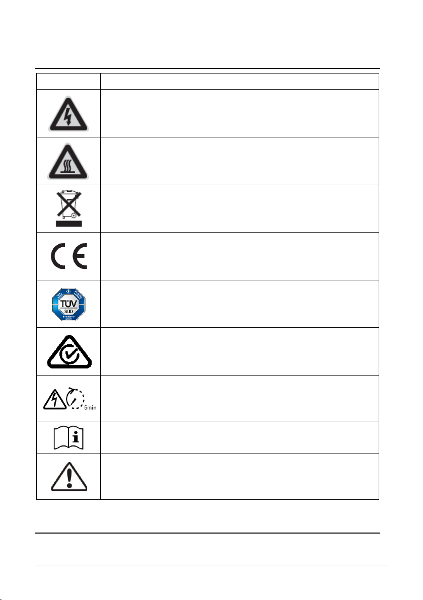
Risk of injury due to electric shock and re caused by high leakage current
• The inverter must be reliably grounded in order to protect property and
personal safety.
Risk of injury due to hot heat sink
• The heat sink may get hot during operon. Do not touch!

9
Possible damage to health as a result of the eects of electromagnetic
radiation
• Please maintain a distance of at least 20cm from the inverter when it is in
Grounding the PV array
• Comply with local regons for grounding the PV array. We suggest the
frames of PV modules must be reliably grounded.
• Do not ground any of the terminals of the strings.
Damage to the seal of the cover in sub-zero conditions
• If you open the cover in sub-zero condion,the sealing of the cover can be
damaged.This can lead moisture entering the inverter.
• Do not open the cover at ambient temperatures lower than -5 .
• If a layer of ice has formed on the seal of the cover in sub-zero
comdions,remove it prior to opening the inverter(e.g. by mel the ice
with warm air). Observe the applicable safety regulaon.

10
Damage to the inverter due to electrostatic discharge
•Touching electronic components can cause damage to or destroy the
inverter through electrostac discharge.
• Ground yourself before touching any component.

11
2.4 Symbols on the label
Symbol Explanation
Danger of life due to electric shock
Risk of burns due to hot surface.
Do not dispose of this inverter with household waste.
CE mark.
Cersafety
The product is TUV-tested and complies with the requirements of the
EU Equipment and Product Safety Act.
RCM Mark
The product complies with the requirements of the applicable
Australian
Danger of high voltage and electric shock, wait at least 5 munites to
allinverter has been disconnected from the grid and PV
array.
Refer to the manual accompanying the inverter.
Risk of danger, warning and cauon
Safety informaon important for human safety. Failure to observe the safety
informaon in this manual may result in injury or death.

13
3 Unpacking
3.1 Scope of delivery
Object Descripon Quanty
A PV Inverter 1 piece
B Wall-mounng bracket 1 piece
C
Mounng accessory kit:
Wall anchors and hexagon bolts (2×)
M5×12 mm pan head screw (1×)
1 set
D DC connector 1 pair / 2 pairs(*)
E AC Plug connector 1 piece
F WiFi sck(oponal) 1 piece ( oponal )
HDocumentaon 1 set
*2 pairs for KSY -4KW-6.2KW-1Ph-2MPPT
A B C D
E F H
Carefully check all of the components in the carton. If anything is missing, contact your
dealer.
3.2 Checking for transport damage
Thoroughly inspect the packaging upon delivery. If you detect any damage to the packaging
which indicates the inverter may have been damaged, inform the responsible shipping
company immediately. We will be glad to assist you if required.

14
4 Mounting
4.1 Ambien
1. Be sure the inverter is installed out of the reach of children.
2. Mount the inverter in areas where it cannot be touched inadvertently.
3. Ensure good access to the inverter for installaon and possible service.
4. To make sure that heat can dissipate, observe the following minimum clearance to
walls, other inverters, or objects:
C
5. The ambient temperature should be below 40°C to ensure opmal operaon.
6. Recommend to mount the inverter under the shaded site of the building or mount an
awning above the inverter.
7. Avoid exposing the inverter to direct sunlight, rain and snow to ensure opmal
operaon and extend service life.
8. The mounng method, locaon and surface must be suitable for the inverter's weight
and dimensions.
Direcon Min. clearance
Upward 300 mm
Sides 200 mm
Downawrd 500 mm
Front 500 mm

15
9. If mounted in a residenal area, we recommend mounng the inverter on a solid
surface. Plasterboard and similar materials are not recommended due to audible
vibraons when in use.
10. Do not put any objects on the inverter.
11. Do not cover the inverter.

16
4.2 Selecng the moung l
1. Mount the inverter verally or ted backward by a maximum of 15°.
2. Never mount the inverter lted forward or sideways.
3. Never mount the inverter horizontally.
4. Mount the inverter at eye level to make it easy to operate and to read the display.
5. The electrical connecon area must point downwards.
Danger to life due to re or explosion
• Do not mount the inverter on mmable construcmaterials.
• Do not mount the inverter in areas where mmable materials are stored.
• Do not mount the inverter in areas where there is a risk of explosion.

17
4.3 ng the inverter with the wall bracket
Mounting procedures:
1. Use the wall bracket as a drilling template and mark the posions of the drill holes. Drill 2
holes required using a drill with 10 mm bit. The holes must be about 70 mm deep. Keep the
drill vecal to the wall, and hold the drill steady to avoid lted holes.
2. er drilling holes in the wall, place two screw anchors into the holes, thench the wall
mounng bracket to the wall using the self-tapping screws and washers delivered with the
inverter.
3. Holding the inverter and aach it lted slightly downwards to the wall bracket.
3. Check both sides of the heat sink to ensure that it is securely in place.

18
4. Push the inverter as far as possible and ch it to both sides of the wall bracket using the
M5 screws.Install an anhelock (oponal), the lock is prepared by customer.
Dismante the inverter in reverse order.

19
5 Electrical Connection
5.1 System layout of units without integrated DC switch
Local standards or codes may require that PV systems are ed with an external DC switch
on the DC side. The DC switch must be able to safely disconnect the open-circuit voltage of
the PV array plus a safety reserve of 20%.
Install a DC switch to each PV string to isolate the DC side of the inverter. We recommend
the following electrical connecon:
5.2 Overview of the conneon area
Object Descripon
A DC SWITCH: switch onfor PV-load.
B DC input: plug-in connector to connect the strings.
C WIFI/GPRS (oponal): transmit and receive Wi-Fi or GPRS signal.
D METER/DRM: connect the monitoring device with network cable.
E AC OUTPUT: plug-in connector, connect the grid.

20
5.3 AC connec
5.3.1 Conditions for the AC connection
Cable Requirements
The grid connecon is established using three
conductors (L, N, and PE).
We recommend the following specicaons for stranded copper wire.
KSY- 1KW-4.2KW- 1Ph - 1MPPT
Object Descripon Value
A External diameter 9 to 14 mm
B Conductor cross-secon 2.5 to 6 mm²
C Stripping length of the insulated conductors approx. 12 mm
D Stripping length of the outer sheath of AC cable approx. 50 mm
The PE conductor must be 8mm longer than the L and N conductors
Larger cross-secons should be used for longer cables.
KSY 4KW-6.2KW -1Ph - 2MPPT
Object Descripon Value
A External diameter 9 to 14 mm
B Conductor cross-secon 4 to 6 mm²
C Stripping length of the insulated conductors approx. 12 mm
D Stripping length of the outer sheath of AC cable approx. 50 mm
The PE conductor must be 8mm longer than the L and N conductors
Informaon on grounding components:
Object Descripon
1 Housing
2 M5 terminal lug with protecve conductor
3 M5×12 pan head screw

25
5.4 DC Connec
5.4.1 Requirements for the DC Conne
Requirements for the PV modules of a string:
• PV modules of the connected strings must be of: the same type,cal alignment and
idenal t.
• The thresholds for the input voltage and the input current of the inverter must be adhered to
• On the coldest day based on stacal records, the open
-
circuit voltage of the PV array must
never exceed the maximum input voltage of the inverter.
• The connecon cables of the PV modules must be equipped with the connectors included in
the scope of delivery.
Danger to life due to high voltages in the inverter
• Before connng the PV array, ensure that the DC switch is switched o
and that it cannot be reaed.
• Do not disconnect the DC connectors under load.
Use of Y adapters for parallel connection of strings
The Y adapters must not be used to interrupt the DC circuit.
• Do not use the Y adapters in the immediate vicinity of the inverter.
The adapters must not be visible or freely accessible.
• In order to interrupt the DC circuit, always disconnect the inverter as
described in this document "Disconnecng the Inverter from
Voltage Sources").
• The posive connecon cables of the PV modules must be equipped with the posive DC
connectors. The negave connecon cables of the PV modules must be equipped with the
negave DC connectors.

26
5.4.2 Assembling the DC connectors
Assemble the DC connectors as described below. Be sure to observe the correct polarity.
Cable requirements:
External diameter: 5 mm to 8 mm
Conductor cross-secon: 2.5 mm² to 6 mm²
Number of conductors: at least 7
Nominal voltage: at least 600V
Proceed as follows to assemble each DC connector.
1. Switch oe DC-switch and secure against being inadvertently switched back on.
Eliminate any exiground faults or short circuits in the strings.
2. Strip the cable as follows:
3. Put the contact barrel with stripped cable in the corresponding crimping notch, ensure
all conductor strands are captured in the contact barrel, and then crimp the contact.

Installaon and Operang Instrucons V00 27
4. Insert contact cable assembly into back of the MC4 plug connector unl it audibly locks
into place.
5. Screw the cap nut by using the torque of 2.6~2.9Nm.
6. er screw the cap nut ghtly, connect the fault-free strings of the PV generator into
DC input connectors on the inverter un it audibly locks into place.
7. When you want to separate the DC connectors, please use the specil to do it.
Please make sure the wedge side of the gers face the MC4 plug connector and push
the tool down, as follows.
8. Please use sealing caps for ght sealing of unplugged DC input connectors.
If using H4 connector, the operang procedures are similar as that of MC4
connector.

28
5.4.3 Conneg the PV array
1. Ensure that the individual miniature circuit-breaker is switched oand ensure that it
cannot be accidentally reconnected.
2. Ensure that the DC switch is switched oand ensure that it cannot be accidentally
reconnected.
3. Ensure that there is no ground fault in the PV array.
4. Check whether the DC connector has the correct polarity.
If the DC connector is equipped with a DC cable having the wrong polarity, the DC
connector must be reassembled. The DC cable must always have the same polarity as the
DC connector.
5. Ensure that the open-circuit voltage of the PV array does not exceed the maximum DC
input voltage of the inverter.
6. Connect the assembled DC connectors to the inverter unl they audibly snap into place.
7. Ensure that all DC connectors are securely in place.
The inverter can be destroyed by overvoltage
If the voltage of the strings exceeds the maximum DC input voltage of the
inverter, it can be destroyed due to overvoltage. All warranty claims become
void.
• Do not connect strings with an open-circuit voltage greater than the
maximum DC input voltage of the inverter.
• Check the design of the PV system.

34
7 Commissioning
7.1 Electrical checks
Carry out the main electrical tests as follows:
Check the PE connecon with a mulmeter: make sure that the inverter’s exposed metal
surface has a ground connecon.
Check the DC voltage values: check that the DC voltage of the strings does not exceed the
permied limits. Refer to the Secon 2.1 "Intended use" about designing the PV system for
the maximum allowed DC voltage.
Check the polarity of the DC voltage: make sure the DC voltage has the correct polarity.
Check the PV array’s insuln to ground with a mulmeter: make sure that the insulaon
resistance to ground is greater than 1 MOhm.
Check the grid voltage: check that the grid voltage at the point of connecon of the
inverter complies with the permied value.
7.2 Mechanical checks
Carry out the main mechanical checks to ensure the inverter is waterproof:
Make sure the inverter has been correctly mounted with wall bracket.
Make sure the cover has been correctly mounted.
Make sure the communicaon and AC cable gland has been mounted properly and
adequately locked.
Risk of injury due to incorrect installation
• We strongly recommend carrying out preliminary checks before
commissioning to avoid possible damage to the device caused by faulty
installaon.
This manual suits for next models
1
Table of contents
Other KSolare Inverter manuals
Popular Inverter manuals by other brands

Generac Power Systems
Generac Power Systems SD275 instruction manual

Dressler
Dressler CESAR 1312 user manual

NSM
NSM TR 132 Use and maintenance manual

UNIRAC
UNIRAC SOLARMOUNT ASCENDER 2-ROW ELEVATED installation guide

Allen-Bradley
Allen-Bradley PowerFlex 700H installation instructions

Wacker Neuson
Wacker Neuson G 3.3AE Operator's manual

Magnum Energy
Magnum Energy MS-PAE Series owner's manual

GÜDE
GÜDE UNI MIG 125 SYN Translation of the original instructions

CPS
CPS SCA Series Installation and operation manual

GENERGY
GENERGY LIMITED 1500I Instructions for use

Westerbeke
Westerbeke BCGA-60HZ Service manual

Toshiba
Toshiba TOSVERT VF-S15 series Function manual