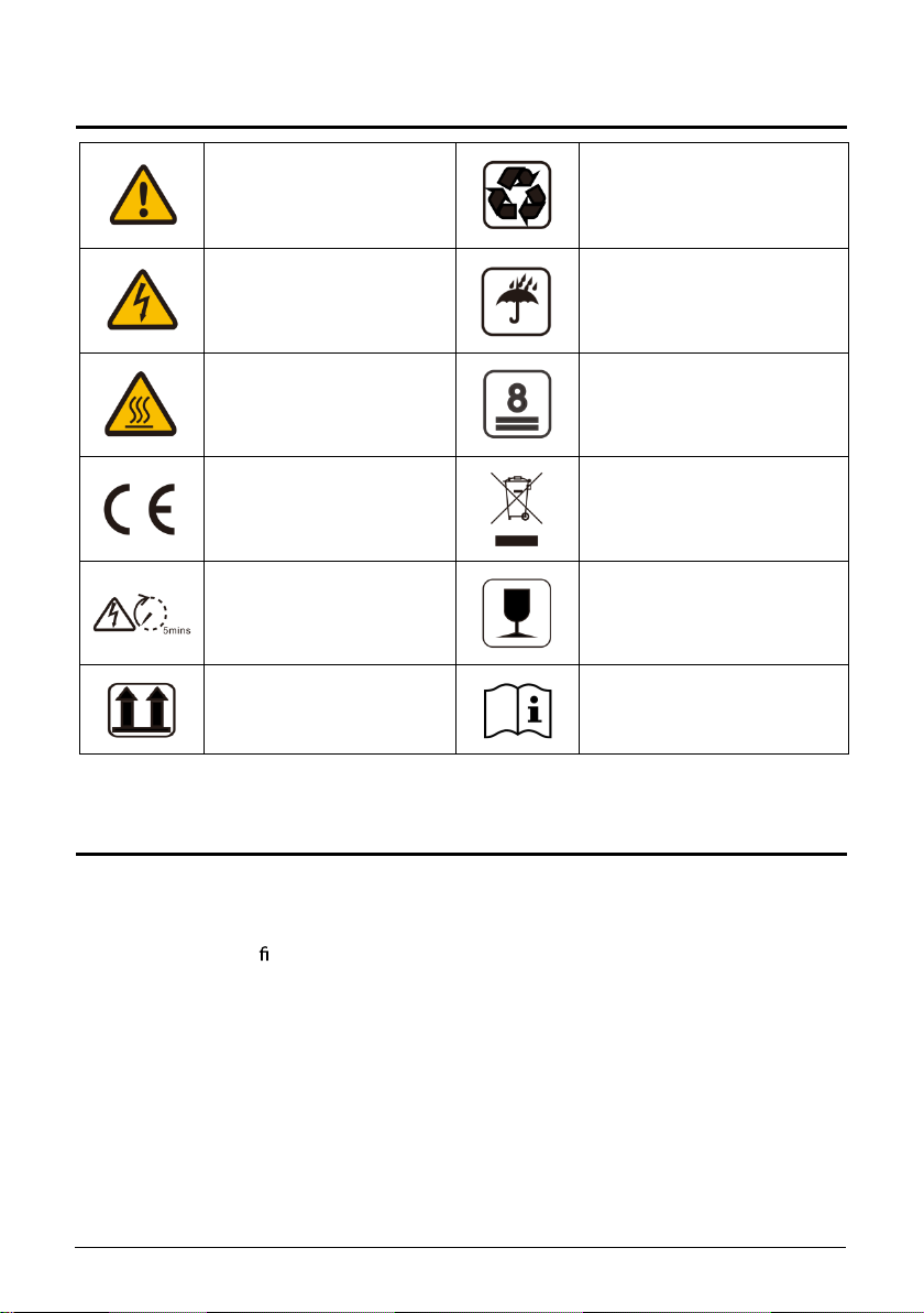
1. SYMBOLS ON THE LABEL
2. SAFETY AND WARNINGS
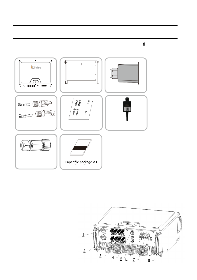
3. 3UNPACKING
3. 1 Scope of Delivery .......................................... .................................................... 5
3. 2 Product Overview ................................................................................... ......... 5
4. 4INSTALLING
4.1 Installation Requirement ............................................................................. 6
4. 2 Mo unting Location ........................................................................................ 7
4. 3 Mounting ................................................................................... ....................... 7
4. 4 Installing the secondary PE cable ........................................................ 8
5. 5COMMISSIONING
5.1 Safety Instructions ........................................................................................... 10
5.2 AC Wire Assembly and Connection ....................................................... 10
5.2.1 AC Commissioning ........................................................................................ 10
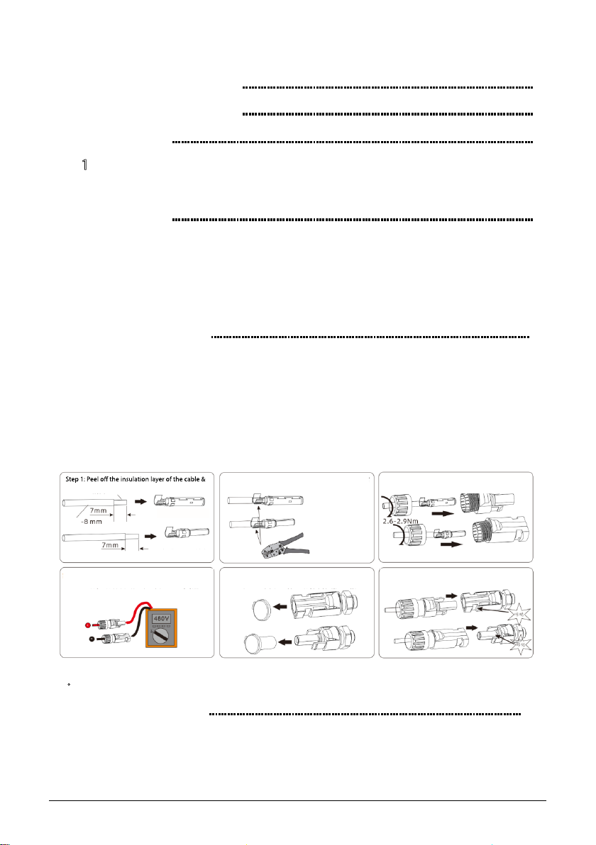
5. 3 DC Wire Assembly and Connection ...................................................... 13
DC Commissioning :
insert it into the corresponding terminal
Positive cold-pressed
terminal
Negative cold-press
terminal
Diameter
Step 2 : Use a suitable crimping pliers to crimp the
corresponding wire
Step 3: Insert the crimped terminal into the corresponding
plastic shell
Step 6: Connect the wired client and machine
Step 4: Check whether the polarity of the connecting cables of the PV string is
correct, and ensure that the open circuit voltage does not exceed the upper
limit of the inverter input
Step 5: Pull out the dustproof cap on the DC terminal of the machine
Note: Please keep the dustproof cap of the unused terminal
5. 4 Residual Current Protection ................................................................ 13
6. 6 COMMUNICATION
6.1 System monitoring via Datalogger -RS485/Wi-Fi/GPRS (Optional) .... 14
1
Table Of Content
3
3
5
14
6