KSolare KSY-3000 User manual

User Manual
5G PRO INVERTER
KSY:- 3KW -12KW-3Ph
Three-Phase Grid-tied Solar Inverter

CATALOGUE
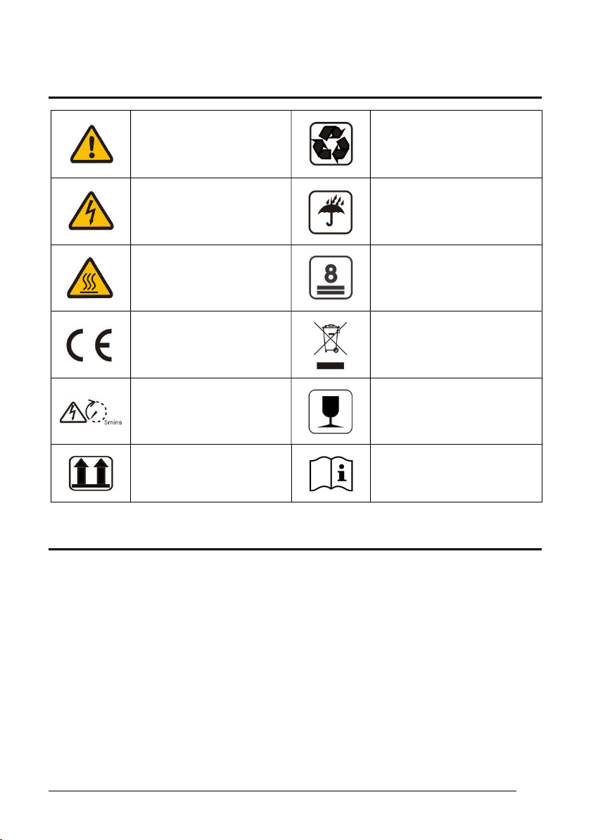
1. SYMBOLS ON THE LABEL ..................................................................................3
2. SAFETY AND WARNINGS ..................................................................................3
3. UNPACKING .........................................................................................................4
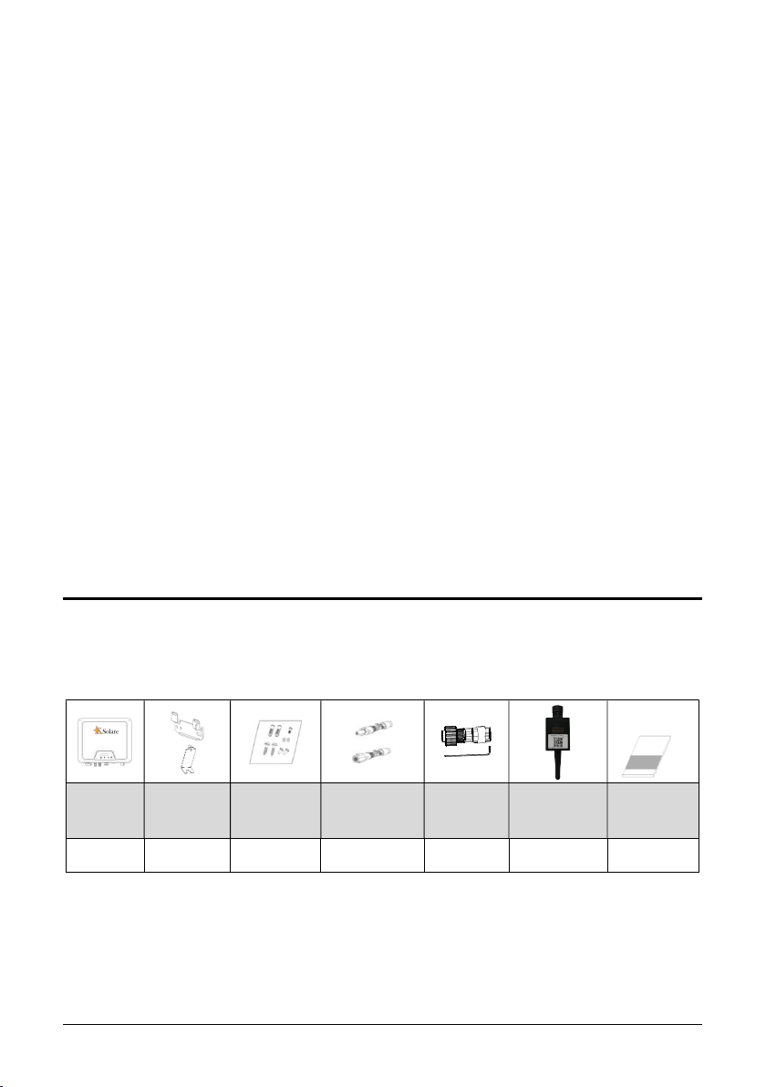
3.1 Scope of Delivery ..............................................................................................................5
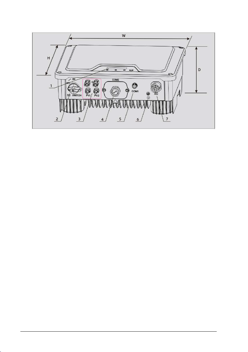
3.2 Product Overview .............................................................................................................5
4. INSTALLING .........................................................................................................6
4.1 Installation Requirement ..................................................................................................6
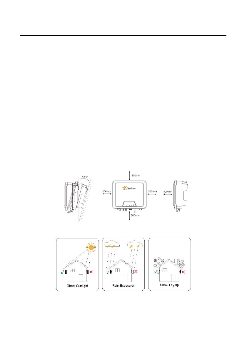
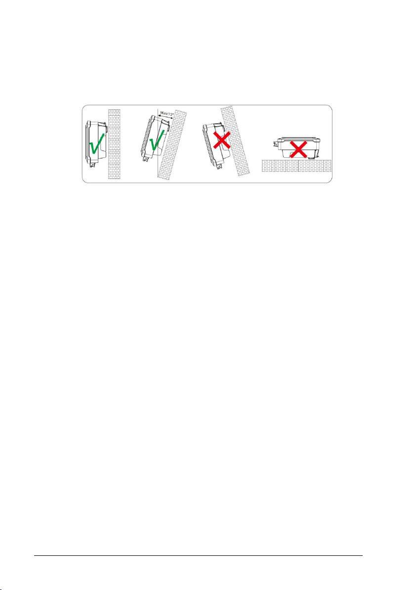
4.2 Mounting Location...........................................................................................................7
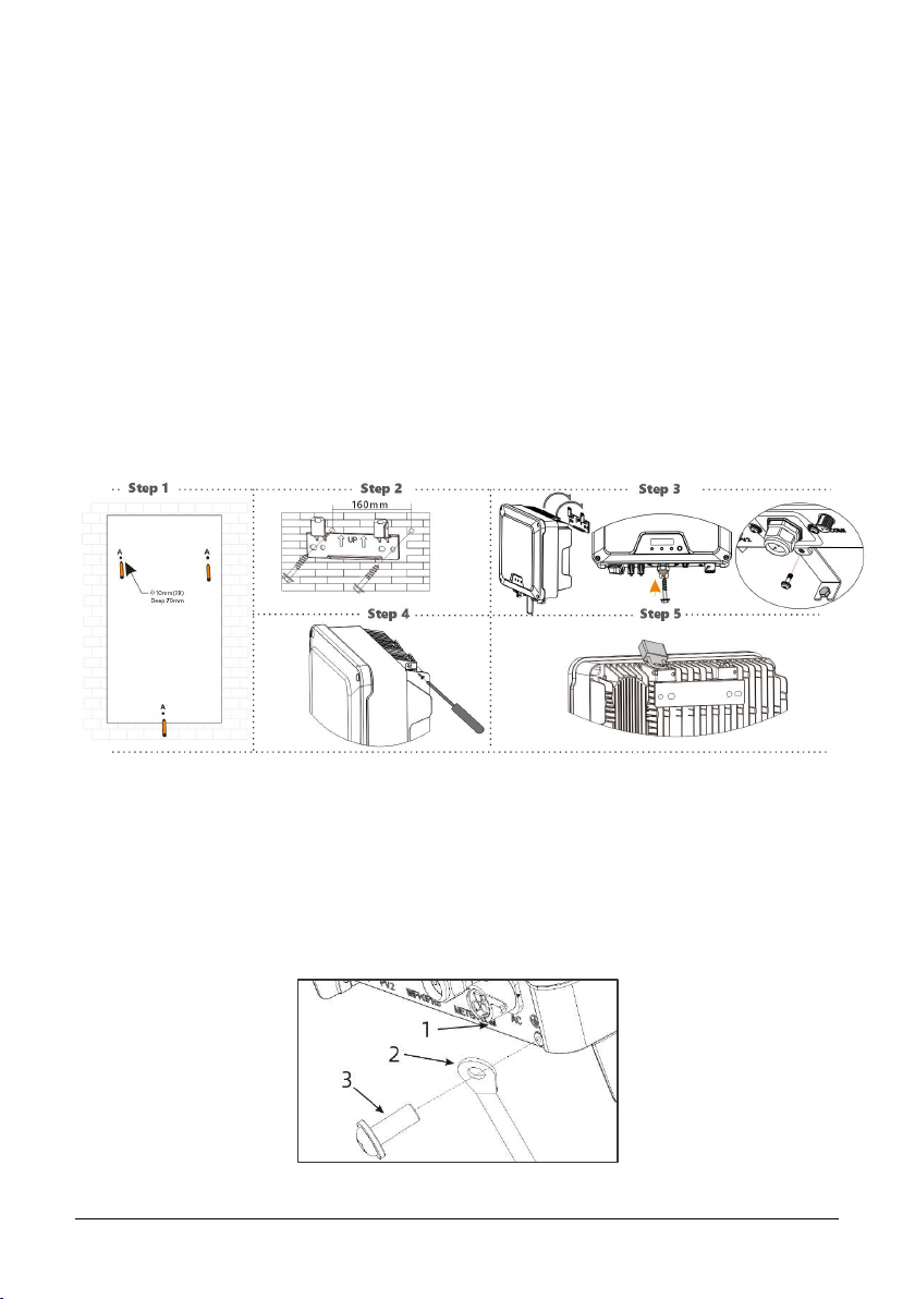
4.3 Mounting ...........................................................................................................................8
4.4 Installing the PE cable ......................................................................................................8
5. COMMISSIONING .............................................................................................9
5.1 Safety Instructions ..........................................................................................................9
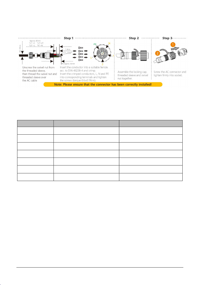
5.2 AC Wire Assembly and Connection ..............................................................................10
5.3 DC Wire Assembly and Connection ..............................................................................11
5.4 Residual Current Protection ...........................................................................................11
6. COMMUNICATION ...........................................................................................12
6.1 System monitoring via Datalogger - RS485/Wi-Fi /GPRS (Optional) ........................12
7. START UP AND OPERATION ...........................................................................14
7.1 Safety Check Before Start Up .........................................................................................14
7.2 Inverter LED Indicators ...................................................................................................15
8. DISCONNECTING FROM VOLTAGE RESOURCES .........................................16
10.
SYSTEM MAINTENANCE ..............................................................................19
9. Fault Finding ..............................................................................17

3
1. SYMBOLS ON THE LABEL
DANGER, WARNING AND
CAUTION
RECYCLABLE AND REUSABLE
HIGH VOLTAGE
AVOID CONTACT
AVOID DAMP AND MOISTURE
HIGH TEMPERATURE
AVOID CONTACT
SHIPMENT STACK LIMIT: 8
CE MARKS
DO NOT DISPOSE WITH
HOUSEHOLD WASTE
PROCEED OPERATIONS
AFTER 5 MINUTES
DISCHARGE
BREAKABLE ITEM
PLACE UPWARDS
USER MANUAL IN PACK
2. SAFETY AND WARNINGS
1. All persons who are responsible for mounting, installation, commissioning,
maintenance, tests, and service of KSOLARE inverter products must be suitably
trained and qualied for corresponding operations. They MUST beexperienced and
have knowledge of operation safety and professional methods. All installation
personnel must have knowledge of all applicable safety information, standards,
directives, and regulations.
2. The product must ONLY be connected and operated with PV arrays of protection
class II, in accordance with IEC 61730, application class A. The PV modules must also

4
be compatible with this product. Power resources other than compatible PV arrays
MUST not be connected and operate with the product.
3. When designing or constructing a PV system, all components MUST remain in their
permitted operating ranges, and their installation requirements MUST always be
fullled.
4. Under exposure to sunlight, the PV array may generate dangerous output in DC
voltage. Contacts with the DC wires, conductors and live components in the inverter
may result in lethal shocks.
5. High voltages ininverter could cause lethal electrical shocks. Before proceeding any
work, including maintenance and/or service, on the inverter, fully disconnect it from
all DC input, AC grid and other voltage sources. There MUST be a 5-minute waiting
time after the full disconnection.
6. The DC input voltage of the PV array MUST never exceed the maximum input
voltage of the inverter.
7. DO NOT touch parts of the inverter during operation as heat will beinduced and
these parts willexceed 60.
3. UNPACKING
3.1 Scope of Delivery
Please inspect and check for completeness in the scope of delivery. Conrm with
purchase order.
INVERTER MOUNTING
BRACKET
MOUNTING
ACCESSORIES
DCPLUGS
(SEALED)
AC
CONNECTOR
COMMUNICATIO
NDATALOGGER
(OPTIONAL)
DOCUMENTS
1 1 1 2 1 1 1

5
3.2 Product Overview
1LED&LCD or LED
2DC Switch
3PV Terminal (s)
4COM1: Wi-Fi/GPRS (Optional)
5COM2: RS485/METER/DRED
6Secondary PE Terminal
7AC Terminal

6
4. INSTALLING
4.1 Installation Requirement
1. Please install the inverter(s) in places that can avoid inadvertent contact.
2. Installation method, location and surface must be tting for the inverter’s weight and
dimensions.
3. Please install the inverter in an accessible location for operation, future maintenance
and service.
4. The inverter performance peaks at ambient temperature lower than 45.
5. When installing in residential or domestic environment, it is recommended to install
and mount the inverter on a solid, concrete wall surface. Mounting the inverter on
composite or plaster boards or walls with similar materials would induce noise during
its operation and is therefore not recommended.
6. DO NOT cover the inverter NOR place any objects on top of the inverter.
7. To ensure sucient room for heat dissipation and maintenance, the clearing space
betweeninverter(s) and other surroundings is indicated below for reference:
8. Avoid direct exposure to sunlight and rain and snow layup.

7
4.2 Mounting Location
1. DO NOT mount the inverter near any inammable materials.
2. DO NOT mount the inverter near any explosive materials.
3. DO NOT mount the inverter on tilting surface over 15° backwards. Please mount the
inverter on a vertical wall surface.
4. DO NOT mount the inverter on any surfaces tilting forward or to either sides.
5. DO NOT mount the inverter on a horizontal surface.
6. For easy installation and operation, please mount the inverter on a height that the
display could match eye level.
7. The bottom side where all commissioning terminals are equipped MUST always point
downwards.

8
4.3 Mounting
1. Use the mounting paper guide as a template and drill holes of 10mm diameter and
70mm depth.
2. Fix the mounting bracket with the screws and expansion bolts packed in mounting
accessories.
3. Hold up the inverter and tilt it slightly forward. Hang up the inverter and attach it to
the mounting bracket. Check both sides of the heat sink to ensure its stably attached.
4. Use M5 screws (T25 screwdriver, torque 2.5 Nm) to attach the heat sink ns to the
mounting bracket.
5. It is recommended to attach the anti-theft lock to the inverter. Lock diameter φ4-
5.5mm recommended.
4.4 Installing the PE cable
1. Insert the grounding conductor into the suitable terminal lug and crimp the contact.
2. Align the terminal lug with the grounding conductor and the ground washer on the
screw. The teeth of the ground washer must be facing the housing.
3. Tighten it rmly into the housing (screwdriver type: T25, torque: 2.5Nm).

9
Information on grounding components:
Object Description
1 Housing
2 M5 terminal lug with protective conductor
3 M5×12 pan head screw
5. COMMISSIONING
5.1 Safety Instructions
1. Measure the frequency and voltage of grid connection and make sure they follow the
inverter’s grid connection specications.
2. An external circuit-breaker on the AC side (or a fuse) at 1.25*AC rated current is
strongly recommended.
3. Reliability of all earth connections must be tested and valid.
4. Before commissioning, disconnect the inverter and the circuit-breaker or fuse, and
prevent accidental reconnection.

10
5.2 AC Wire Assembly and Connection
5.2.1 AC Commissioning
5.2.2 AC Switch Types
Please install an individual 2-stage miniature circuit breaker according to the following
specications.
Model Maximum output current(A)AC Breaker Rated current(A)
6150003-KSY
615.60004-KSY
615.80005-KSY
6190006-KSY
52310008-KSY
522.5100001-KSY
528100021-KSY

11
5.3 DC Wire Assembly and Connection
1. PV modulesof the connected strings must be of: the same time, identical alignment
and tilting angle.
2. Before commissioning and connecting the PV arrays, the DC switch MUST be open.
3. Parallel strings must have the same number of modules.
4. It is mandatory to use the DC connectors within package for the connection of PV
arrays.
5. The polarity of the PV arrays MUST be compatible to the DC connectors of the
inverter.
6. The DC input voltage AND DC input current of the PV array MUST never exceed the
maximum input allowance of the inverter.
DC Commissioning:
5.4 Residual Current Protection
This product is equipped with residual current protection device internally, in accordance
with IEC 60364-7-714. An external residual current protection device is not needed.
If the local regulation demands otherwise, it is recommended to install a 30mA Type B
residual current protection device.
1000V
1000V

12
6. COMMUNICATION
6.1 System monitoring via Datalogger - RS485/Wi-Fi /GPRS (Optional)
6.1.1 Wi-Fi /GPRS Datalogger Installation
1. Unpack the Datalogger from package.
2. Unscrew the cap in COM1 port and plug
the Datalogger in and tighten.
3. For user guidance and conguration of
Datalogger, please refer to the
corresponding KSOLARE Wi-Fi Stick Guide manual, which is available in
printed form inside Documents pack, or an online manual on KSOLARE
website at .
6.1.2 RS485 Installation
If the communication module is connected via RS485:
Step 1: Unscrew with T25 screwdriver and remove the COM sealing plate. The terminals of
DRED/Meter/RS485 is exposed as indicated.
13
www.ksolare.com

Step 2: Unscrew the nut of cable gland and take out the rubber cylinders. Please seal the
cable gland properly if there is an unused hole to prevent moisture and dust.
Step 3: Connect the crimped cables to RS485 / Meter terminals and secure by (blade
0.4x2.5) screwdriver.
Step 4: Tighten the nut to prevent the cable from wobbling.
Step 5: Put on the COM sealing plate and rmly tighten the screws to prevent moisture and
dust. (Screwdriver type: T25; Torque: 2.5 Nm)
When installing RS485, the COM sealing plate needs to be removed. All operation MUST
NOT proceed until AC and DC power is securely disconnected and discharged to
prevent electric shocks.

14
7. START UP AND OPERATION
7.1 Safety Check Before Start Up
Please check before switching on any voltage resources connected to the inverter and
closing inverter’s DC switch:
1. Grid Voltage: Check the grid voltage at point of connection at the inverter complies
with permitted range of the inverter.
2. Mounting Bracket: Check if the mounting bracket is properly and securely installed.
3. Mounting of the inverter: Check if the inverter is properly mounted and attached to
the mounting bracket.
4. DC Connectors: Check if the DC connectors are installed correctly on terminals.
5. AC Connectors and Wire Assembly: Check if wires are assembled correctly on the AC
side and if the AC connector is properly and securely installed. Check if the AC
connector is rmly plugged into AC terminal.
6. Cables: Check if all cables are reliably connected. Check if the connections are
eective, while the insulations are undamaged.
7. Groundings: Check all groundings using multimeter and if all exposed metal parts of
the inverter are properly grounded.
8. DC Voltage: Check if the largestopen-circuit voltage of PV arrays complies with the
permitted range.
9. DC Polarity: Check if the wires from DC voltage resource are connected to terminals
with correct polarity.
10. Grounding Resistance: Check if the grounding resistance of PV strings >1MOhm using
a multimeter.
After all installation and checks, close the AC circuit-breaker, then the DC switch. The
inverter will start to operate when DC input voltage and grid conditions meet the
requirements of inverter startup.

15
7.2 Inverter LED Indicators
When the inverter operates, LED symbols on display have the following meanings:

16
8. DISCONNECTING FROM VOLTAGE RESOURCES
Before proceeding any operations on inverter, please disconnect the inverter from all
voltage resources as described in this manual.
Following these steps in described sequence are mandatory.
1. Disconnect miniature circuit-breaker and prevent from unintentional reconnections.
2. Open the DC switch and prevent the switch from closing unintentionally.
3. Use clamps to ensure there is no electrical current in DC wires.
4. Disconnect all DC connections and resources. Unplug the DC connectors, and DO
NOT pull the cables.
5. Use multimeter to ensure the voltage on DC terminals of inverter is 0.
6. Unscrew and remove the AC connector.
Danger to life due to high voltages.
Inverter capacitors need 10 minutes to be completely de-energized. Please
wait for 10 minutes to remove the cover.
When an error occurs, DO NOT remove the cover of the inverter onsite. Improper
operations and attempts may induce electric shock.

17
Fault Finding
Classifications of Fault Information
Fault
Location
Fault Type
Error Message
DC Side Fault
Failures caused by PV side wiring
F5
- PV voltage too high
F6
- Surface insulation resistance
error
F7
- GFCI exceeds the permissible
range
AC Side Fault
Various faults caused by abnormal
power grid or AC side wiring
F0
- 10min average voltage over
the protection range
F9 - No gird
F10
- The grid voltage is out of
range
F11
- The grid frequency exceeds
the range
F19
- The voltage of N-PE is too
high
Inverter Fault
Fault code caused by inverter itself
F1 - MCU fault
F2 - Current sensor fault
F3 - GFCI sensor fault
F4 - Relay fault
F12 - Dc component out of range
F13 - EEPROM fault
F14
- Master and slave DSP
communicationfailure
Others
It may be caused by external
installation environment, PV side
and inverter itself. Further
Diagnoses needed.
F8
- Temperature is out of range
F15 - BUS voltage is too high
F16 - BUS voltage is too low
F17
- DRM S9 fault
F18
- DRM S0 fault

18
Log complaint on h�ps://bit.ly/3eRZba9
Contact 8530111222 / 7888009282 / 7030955507 /01
Fault code
Fault
Solution
Fault 9 No Grid 1. Check Ac ( grid ) Voltage In connector
2. Phase to Neutral voltages
200V – 250V
3. Phase to Phase Voltage
400V – 450V
Fault 10
The grid voltage is out
of range
1. Check Grid voltages
2. Phase to Neutral voltages
200V – 250V
3. Phase to Phase Voltage
400V – 450V
Fault 19
The voltage of N-PE is
too high
1. Check Ac side Neutral to Ground
voltage less than 15V
Waiting
-
1. Check Connection in AC connector
2. Grid voltages ininverter
3. check version & make Online system
Fault code
Fault
Solution
Fault 5
PV voltage too high
1. Check DC side voltages
2. For single phase voltage under 500V
3. For Three phase voltage under 1000V
Fault 6
Surface insulation
resistance
error
1.Check DC side Positive to Ground voltage
& Negative to Ground voltage
Display Off
-
1.Checkstring polarity
2. Check DC voltage
For single phase 1kw -3.3kw start up
voltage 80V – 500V
For single phase 4kw -6.2kw start up
voltage 100V – 550V
For Three phase 3kw -60kw start up
voltage 200V – 1000V
For Three phase 60kw -110kw start
up voltage 250V – 1100V
3. Loose connection in string / loose
crimping
Faults & Troubleshooting
Grid (AC) Side faults
( Panel ) DC Side faults

11. SYSTEM MAINTENANCE
Content Maintenance Measures Cycle
System
Cleaning
• Check if the heat sink is covered and dusted
Annually OR Half a year
System Status
• Inspect the enclosure for damage/deformation
• Check if the parameters are normal during
operation
Half a year
Commissioning
• Check if the cables are loose
• Check if the cable insulations are damaged,
especially the parts in contact with metal surfaces
Half a year after rst
commissioning
Annually OR Half a year
Grounding • Check if the cables are securely grounded
Half a year after rst
commissioning
Annually OR Half a year
19

Poonam petrol pump, KSolare Technology Park, Sr.No. 62,
Hissa No.03, Mangdewadi, Pune, Maharashtra 411046
Enquiry Email:
Service Email:
Contact:
8530111222
Follow Us On
This manual suits for next models
6
Table of contents
Other KSolare Inverter manuals
Popular Inverter manuals by other brands

Samlexpower
Samlexpower PSE-12125A owner's manual

CPS
CPS SCA Series Installation and operation manual

Kaco
Kaco blueplanet 50.0 TL3 Basic operation instruction

Fuji Electric
Fuji Electric FRENIC 5000G11S/P11S instruction manual

Sigineer Power
Sigineer Power M6048D user manual

Carrier
Carrier 69GL15-114 Operation and service

Lincoln Electric
Lincoln Electric MOTOVAR MV 20 Safety instruction for use and maintenance

Connectland
Connectland G-180AF user guide

AIMS Power
AIMS Power PWRINV400W instruction manual

Tektronix
Tektronix MTS4SAV3 user manual

Replus
Replus Replus-250 user manual

Generac Power Systems
Generac Power Systems 00862-1 Installation and owner's manual