KSolare KSY-60KW Series User manual

5G MEGA INVERTER
KSY-60KW/70KW/75KW/80KW Series
Three-Phase Grid-Tie Solar Inverter

About this manual
For Readers
This manual is helpful for technicians who install, debug, operate and maintain string inverters of
KSOLARE. Please read this manual carefully before operates the product. Readers are required to
know the basic knowledge about electric components, wiring, signs and mechanical drawings.
Outlines
Chapter Contents
1 Safety Precautions This chapter describes the safety precautions when transporting, storing, installing,
running and maintaining the Inverter.
2 Product Description This chapter describes the basic principles, naming rules, product configuration and
data.
3 System Installation This chapter describes the unpacking inspection, installation tools, installation
environment, reserved space, fixing method, cable connection.
4 Commissioning
Guide
This chapter describes the inspection before startup, commissioning and startup of
string inverter.
5 Maintenance and
Troubleshooting
This chapter describes the daily maintenance methods, maintenance intervals and
troubleshooting of the product.
6 Inverter Handling
Guide
This chapter describes the basic requirements and precautions when disassembling,
replacing, and scrapping the inverter.
Warning Signs in This Manual
DANGER
Major potential danger (especially refer to high voltage danger). Failure to observe
the rules might cause severe personal injury or property loss.
WARNING
Ordinary potential danger. Failure to observe the rules might cause personal injury
or property loss.
CAUTION
Ordinary potential danger. Failure to observe the rules might cause malfunction of
the equipment or property loss.
Glossaries and Abbreviations
Glossaries/Abbreviations Description
MPPT Maximum power point tracking
Photovoltaic string Multiple solar cell arrays in parallel or series
EEPROM Electrically erasable programmable read-only memory

Contents
1 Safety Precautions ............................................................................................................................. 1
1.1 Transport.................................................................................................................................... 1
1.2 Storage....................................................................................................................................... 1
1.3 Installation .................................................................................................................................. 2
1.4 Operating ................................................................................................................................... 2
1.5 Maintenance............................................................................................................................... 3
2 Product Description ........................................................................................................................... 4
2.1 Product Introduction ................................................................................................................... 4
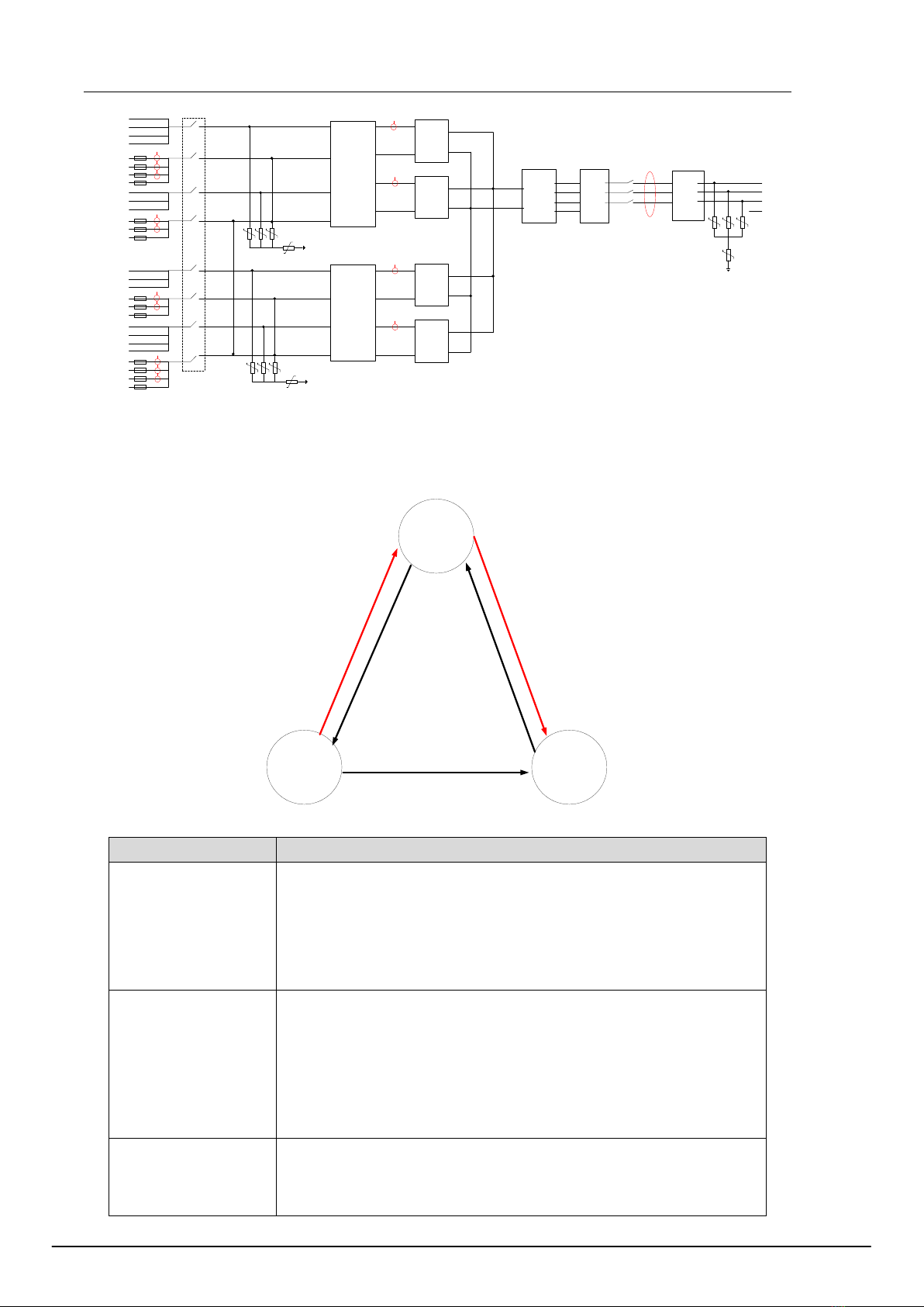
2.1.1 Schematic Diagram ........................................................................................................................ 4
2.1.2 Operating Mode.............................................................................................................................. 5
2.2 System Configuration and Application....................................................................................... 6
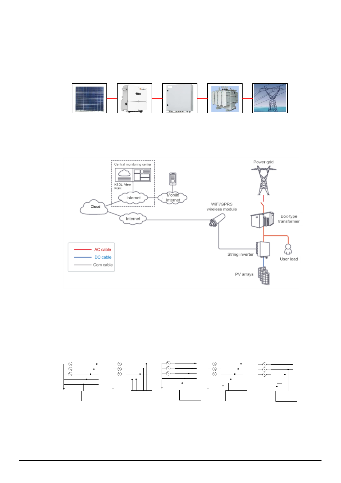
2.2.1 Application Description................................................................................................................... 6
2.2.2 Supported Grid Form...................................................................................................................... 6
2.3 Naming Rules............................................................................................................................. 7
2.4 Nameplate Label ........................................................................................................................ 7
2.5 Inverter Configuration ................................................................................................................ 7
2.6 Labels on the Package ............................................................................................................ 9
2.7 Warning Signs on the Inverter ................................................................................................. 9
3 System Installation ........................................................................................................................... 11
3.1 Unpack and Inspect ................................................................................................................. 11
3.2 Installation Tool Preparation .................................................................................................... 11
3.3 Installation Environment Requirements ................................................................................... 11
3.4 Reserved Space Requirement................................................................................................. 12
3.5 Installation Method ................................................................................................................... 13
3.5.1 Pole Mounting with Hoops............................................................................................................ 13
3.5.2 Pole Mounting with Screws .......................................................................................................... 13
3.5.3 Wall/Bracket Mounting ................................................................................................................. 13
3.6 Electrical Connections ............................................................................................................. 14
3.6.1 Cable Requirements..................................................................................................................... 14
3.6.2 Cable Selection ............................................................................................................................ 15
3.6.5 Connect the Ground Wire............................................................................................................. 15
3.6.6 Open the Lower Door Panel ......................................................................................................... 16
3.6.7 Connect the AC Output Cable ...................................................................................................... 16
3.6.8 Connect Communication Cable.................................................................................................... 17
3.6.9 Connect the DC Input Cable ........................................................................................................ 17
4 Commissioning Guide ..................................................................................................................... 20
4.1 Check before Power On........................................................................................................... 20
4.2 System Power On .................................................................................................................... 20
4.3 System Power Off .................................................................................................................... 20
5 Fault and Troubleshooting .......................................................................................................... 29
5.2 Troubleshooting ....................................................................................................................... 30

1
1 Safety Precautions
In this chapter, it describes the safety precautions that must be observed when installing, operating and
maintaining the inverter. Please read them carefully before operation and follow them in operation
process; otherwise it might cause damage to the inverter, the generator and related equipment’s or
cause serious injury or loss of life.
When you use and operate the inverter, please take special attention to:
DANGER
1. Only the qualified personnel are allowed to install, operate and maintain the inverters.
2. Do NOT incline or collide the product in transportation.
3. Do NOT make any liquid, sundries or rubbishes enter inside as they might cause short circuit inside the
inverter.
4. Inverter must be disconnected with AC grid before completion of installation and maintenance.
5. Related protective measures are required to avoid electric shock or fire accident.
WARNING
Please do not place inflammables and explosives around the inverter to ensure environmental safety.
1.1 Transport
WARNING
1. When transporting, it is necessary to ensure that the inverter is packaged properly and the cabinet is
fixed upwards to avoid strong vibration and collision.
2. In order to keep the inverter in good condition during transportation, it is important to use packaged
transport and operate according to the labels on the package. For the meaning of the logos, please
refer to 2.6 Signs on Package.
3. The transportation environment must meet the requirements. Please refer to 2.10 Ambient
Requirements.
1.2 Storage
WARNING
The storage environment of the string inverter must meet the corresponding requirements. Please refer to
2.10 Ambient Requirements.
About long-term storage:
Before or after the installation and commissioning, if the string inverter is in the no-power supply state for
more than three weeks, it is regarded as long-term storage. Long-term storage of string inverters requires
attention to the following issues:

User Manual
2
Put the desiccant into the cabinet and package the whole machine with packaging materials.
When storing equipment, pay attention to ventilation and moisture. Stagnant water is strictly forbidden
in the storage environment.
Pay attention to the harsh environment, such as quenching, sudden heat, collision, dust, etc., to avoid
damage to the string inverter.
Regular inspections are required, usually not less than once a week. Check whether the packaging is
intact to avoid pest bites. If it is damaged, it needs to be replaced immediately.
If the storage time exceeds half a year, the package should be opened for inspection, repackaged, and
desiccant replaced.
It is strictly forbidden to store the device without packaging.
1.3 Installation
DANGER
1. Before operating the internals of the string inverter, it must be confirmed that the input switch DC
Switch of the string inverter and the circuit breaker corresponding to the AC side of the inverter are in
the off state, and the housing of the inverter is reliably guaranteed.
2. The string inverter must be grounded according to the specifications. The size of the grounding
conductor must meet the requirements of safety regulations to ensure the safety of personnel.
WARNING
1. During installation, it is necessary to ensure that the string inverter’s installation environment is well
ventilated and heat-dissipating, and the device should not be directly exposed to sunlight.
2. The fixing of the string inverter is recommended by two people working together to avoid mechanical
damage. During the installation process, safety measures should be taken to prevent bruises.
3. During installation and maintenance, it is necessary to prevent liquid, dust or debris from entering the
inside of the string inverter. Conductive liquids and debris may cause internal short circuit of the string
inverter, resulting in equipment damage.
4. When connecting the wiring of the external cable to the string inverter, the installation torque of the
power cable must be ensured. Excessive torque may cause fatigue damage of the screw while too
small torque may cause the contact resistance to become large, resulting in overheating.
5. The power cable terminals connected to the string inverter must comply with national standards. If the
terminals are not in accordance with the standards, the power cable may be overheated. In severe
cases, a fire may occur.
6. The installation site must meet the requirements of the operating environment. Please refer to 2.10
Environmental Requirements.
1.4 Operating
DANGER
1. During the operation of the string inverter, it is necessary to ensure that the door panel of the string
inverter is locked to prevent personal injury such as electric shock, and to prevent salt, moisture, dust
or other conductive substances in the air from entering the string inverter.
2. When the string inverter is powered on, it is prohibited to touch the internal single boards, devices,
cables and terminals of the string inverter and to plug and unplug the external terminals.
3. In case of any fault, abnormal smell or sound of the string inverter, please immediately switch off the
DC Switch of the string inverter and the circuit breaker on the AC side of the inverter.

1 Safety Precautions
3
WARNING
1. Power on the string inverter only after all installation work is completed and cables are not connected
incorrectly.
2. It is prohibited to conduct any insulation resistance test or voltage withstand test on the string inverter.
Wrong voltage withstand test will damage the string inverter.
3. When conducting insulation withstand voltage test on external equipment of the string inverter, the
wiring between the string inverter and the external equipment must be disconnected.
1.5 Maintenance
DANGER
1. Before maintenance work, you must first disconnect the AC output side circuit breaker, then disconnect
the input switch DC Switch, and wait at least 5 minutes before operating the string inverter.
2. During the maintenance process, try to avoid irrelevant personnel from entering the maintenance site.
3. Please maintain the string inverter under the condition that you are familiar with and understand the
contents of this manual, and have suitable tools and test equipment.
4. For personal safety, please wear insulating gloves and anti-smashing shoes.
WARNING
The string inverter must be checked and maintained regularly. For details, refer to 5 Maintenance and
Troubleshooting.
--End of the chapter--

4
2 Product Description
2.1 Product Introduction
The KSY MEGA series string inverter is three-phase string-type grid-connected inverter independently
developed by Ksolare Energy Pvt. Ltd. Its main function is to convert the DC power generated by the
PV string into AC power and feed it into the power grid.
KSY MEGA 60KSY and KSY MEGA 70KSY have 12 input interfaces;
KSY MEGA 75KSY and KSY MEGA 80KSY-M have 14 input interfaces
Among them, KSY MEGA 80KSY-M is suitable for 500VAC/10kV (35KV) medium voltage grid-
connected scenarios, such as large-scale ground photovoltaic power stations and distributed
photovoltaic power plants above 400kW;
KSY MEGA 60KSY, KSY MEGA 70KSY and KSY MEGA 75KSY are suitable for 400VAC low-voltage
grid-connected scenarios, such as village-level photovoltaic power stations or industrial and commercial
rooftop photovoltaic power stations below 400kW.
2.1.1 Schematic Diagram
PV strings are connected to the inverter through branches. There are MPPT circuits inside the inverter
to track the MPPT of the strings, and then convert the DC power to three-phase AC power through the
inverter circuit. The schematic diagram is shown below.
1+
2+
1-
2-
3+
4+
3-
4-
5+
6+
PE
Input EMI
filter
DC switch
Input EMI
filter
PE
MPPT
circuit
1#
MPPT
circuit
2#
MPPT
circuit
3#
MPPT
circuit
4#
BUS+
BUS-
Three-
phase
inverter
circuit
LC
filter
RCD leakage
current
detection
Output
EMI
filter
N
A
B
C
fuse
Current hall
5-
6-
7+
8+
7-
8-
9+
10+
9-
10-
11+
12+
11-
12-
Figure 2-1 Schematic diagram of KSY MEGA 60KW /KSY MEGA 70KW
13+
1+
13-
1-
2+
4+
2-
4-
5+
6+
PE
Input EMI
filter
DC switch
Input EMI
filter
PE
MPPT
circuit
1#
MPPT
circuit
2#
MPPT
circuit
3#
MPPT
circuit
4#
BUS+
BUS-
Three-
phase
inverter
circuit
LC
filter
RCD leakage
current
detection
Output
EMI
filter
Fuse Current hall
5-
6-
7+
8+
7-
8-
9+
10+
9-
11-
11+
12+
12-
14-
3+
3-
14+
10-
N
A
B
C
Figure 2-2 Schematic diagram of KSY MEGA 75KW,KSY-80KW

User Manual
5
13+
1+
13-
1-
2+
4+
2-
4-
5+
6+
PE
Input EMI
filter
DC switch
Input EMI
filter
PE
MPPT
circuit
1#
MPPT
circuit
2#
MPPT
circuit
3#
MPPT
circuit
4#
BUS+
BUS-
Three-
phase
inverter
circuit
LC
filter
RCD leakage
current
detection
Output
EMI
filter
PE
A
B
C
Fuse Current hall
5-
6-
7+
8+
7-
8-
9+
10+
9-
11-
11+
12+
12-
14-
3+
3-
14+
10-
Figure 2-3 Schematic diagram of KSY MEGA 80KW -M
2.1.2 Operating Mode
KSY MEGA three-phase string inverter has three working modes: standby mode, running mode, and
shutdown mode. The switching conditions of the three modes are shown as follows.
Standby
Mode
Operation
Mode
Shutdown
Mode
Operation mode to standby mode:
Insufficient sunshine or DC switch is
disconnected
Standby mode to operation mode:
Abundant sunshine without
system faults
Fault or shutdown command is detected
Standby mode to
shutdown mode: fault or
shutdown command is
detected
Shutdown mode to standby
mode: fault is deleted or
startup command is detected
Figure 2-4 KSY MEGA string inverter operating mode
Operating mode Description
Standby
1
)Standby mode mainly means that the external environment does not meet
the operating conditions of the inverter such as insufficient light and the
disconnection of DC input switch. In this mode, the inverter continuously
self-tests and enters the operating mode once the operating conditions are
met.
2
)In the standby mode, if the inverter detects a shutdown command or finds
a fault after the power-on test, it enters the shutdown mode.
Running
I
n the running mode, the inverter converts the DC power of the PV string into
AC
power and feeds it into the grid.
T
he inverter performs MPPT operation to make the PV string output maximum
po
wer.
I
f the inverter detects a fault or a shutdown command, it enters the shutdown
m
ode.
I
f it is detected that the input power of the PV string is lower than the grid-
c
onnected power generation condition, it enters the standby mode.
Shutdown
I
f the inverter detects a fault or a shutdown command during standby or
ope
ration, it switches to the shutdown mode.
I
n the shutdown mode, if the inverter detects that the fault has been cleared or
a
power-on command, it enters the standby mode.

2 Product Description
6
2.2 System Configuration and Application
2.2.1 Application Description
Figure 2-5 shows the application of the string inverter, and Figure 2-6 shows the networking design
scheme of the distributed PV power station.
Photovoltaic
panels
String
inverter
AC power
distribution unit
Isolation
transformer
Grid
Figure 2-5 Application schematic diagram of string inverter
Figure 2-6 Networking scheme of distributed PV power station
2.2.2 Supported Grid Form
The power grid forms supported by KSY MEGA 60KW , KSY MEGA 70KW and KSY MEGA 75KW
include TN-S, TN-C, TN-C-S, TT, IT; KSY MEGA 80KW -M only supports the form grid of IT.
String
Inverter
L1
PE
L2
L3
N
PE
TN-S
L1
PE
L2
L3
PEN
TN-C
L1
PE
L2
L3
N
TN-C-S
PE PE
PE
PE
L1
PE
L2
L3
N
TT
PE
PE
L1
L2
L3
IT
PE
PE
String
Inverter
String
Inverter
String
Inverter
String
Inverter
Figure 2-7 Schematic diagram of various power grid forms

User Manual
7
2.3 Naming Rules
Figure 2-8 Naming rules
2.4 Nameplate Label
Note: The data is for reference only. For more details, please refer to the physical object or technical
agreement of the corresponding product.
2.5 Inverter Configuration
This section describes the internal components, back components and bottom interfaces of the string
inverter.
Note: KSY MEGA 60KW , KSY MEGA 70KW , KSY MEGA 75KW and KSY MEGA 80KW
share same
appearance, and there are 14 groups of PV terminals at the bottom (only 12 groups of terminals are used for
60KW and 70KW , and the other two groups which are not used should be sealed).
CAUTION
There are components on the board that are very sensitive to static electricity. Anti-static measures must be
taken before touching the board.
When touching the board, be careful not to scratch the electrical components.
1
3
2
No. Label Device name
1 Upper door
2 LED indicator
3 Lower door
Figure 2-9 Front view of the inverter
The LED indicators from left to right are described as follows:
Table 2-1 LED Indicator Description
Indicator light Meaning Status Description
PV and grid
connection
Blue light on The PV side and the grid are connected
normally
Blue light fast blinking The grid is connected normally but the PV side
is connected abnormally

2 Product Description
8
Blue light slow blinking The PV side is connected normally but the grid
is not connected
Blue light off Both the PV side and the grid are not
connected
Grid-connected
operation
Blue light on The inverter is in grid-connected power-on
state
Blue light off The inverter is neither grid–connected nor
powered on
Communication
indication
Blue light slow blinking Communication normal
Blue light off Communication abnormal
Alarm
indication
Red light slow blinking Prompt alarm: PID power supply operation
instruction
Red light fast blinking Abnormal alarm
Red light solid on Fault alarm
Remarks:
Slow blinking: 1 second on and 2 seconds off in cycles;
Fast blinking: 0.5 seconds on and 0.5 seconds off in cycles.
1
3
2
No. Label Device name
1 Handle
2 Mounting rack
3 Cooling fan
Figure 2-10 Back view of the inverter
1
2
34
6
5
60KTL,70KTL,75KTL and 80KTL-M
No Label Device name
1 DC SWITCH DC switch

User Manual
9
2 1+ ~ 12(14)+ PV+ terminal block
3 1+ ~ 12(14)- PV- terminal block
4 AC OUTPUT AC output terminal waterproof lock head
5 WiFi/GPRS communication interface
6 RS485 output terminal
Figure 2-11 Bottom view of the inverter
2.6 Labels on the Package
On the outer packaging of the product, there are some labels to guide the user to transport and store the product.
The meanings indicated by the logo are as follows:
No stacking
Handle with care. Avoid
damage to the converter
caused by intense collision and
friction in the process of
transportation and movement.
No stepping
Keep dry. Prevent the inverter
from getting wet or damp
Place vertically
and no tilting
No rollover
Front side
Back side
2.7 Warning Signs on the Inverter
In order to ensure the personal and property safety of users when using this product and avoid
accidents, the following warning labels may be placed inside and outside the string inverter to remind
users of safety precautions during operation.
Protective earthing: PE terminals need to be reliably grounded to ensure the
safety of both operation personnel and equipment.
General warning: This part may have other potential dangers except high voltage
danger. Please watch out!
High voltage danger: This part may have high voltage danger. Please watch out!
Hot surface: Pay attention to the hot surface to prevent burns.

2 Product Description
10
Refer to the user manual: Please refer to the corresponding instructions in the
user manual before operation.
Discharge identification: This equipment has an energy storage device. Before
maintenance, it is necessary to wait for the energy storage device to discharge to
prevent electric shock. The waiting time is not less than the indicated discharge
time.

11
3 System Installation
3.1 Unpack and Inspect
After confirming that the outer packaging is intact, please carry out the unpacking inspection. Unpack
the packaging box and check whether the appearance of the string inverter is in good condition. When
opening the package, be careful to use the tool to avoid scratching the string inverter.
Although the inverter has been strictly tested and inspected before leaving factory, accidental damage
might happen during transportation. Please inspect and check the product as soon as you receive it. If
there is any damage or omission, please contact us and we will help you as soon as possible.
3.2 Installation Tool Preparation
Tool or device Purpose Remarks
4#Inner hexagon spanner Disassemble and assemble of the
lower door panel of the inverter
Phillips screwdriver (PH2) Fasten the grounding screws and
pegboard screws Bolt specifications: M6 and M8
Tube type crimping pliers Crimp the communication cable
terminals
Socket wrench Wire the output cable Bolt specifications:M8
MC4 crimping pliers Crimp the MC4 terminals
The input cable needs to be crimped
into the MC4 terminal before it can be
connected to the PV+/PV- terminal on
the inverter
MC4 removal tool Remove MC4 terminal
Wire stripper Strip wire
Multimeter Measure voltage to ensure wiring
and installation safety
Safety equipment Necessary labor protection Insulating shoes, gloves, etc
3.3 Installation Environment Requirements
The environmental requirements for the installation of string inverter are shown in "1 Safety
Precautions".
The installation mode and position must be suitable for the weight and dimension of the string
inverter. See "2.9 Mechanical Parameters".
The string inverter should be installed in a well-ventilated environment to ensure good heat
dissipation. Avoiding inverter direct sunlight, rain and snow can prolong the life of inverter. It is
recommended to choose sheltered installation sites. If that cannot be satisfied, please set up a
sun shading shelter.
During the operation of the string inverter, the temperature of the chassis and the radiator will be
relatively high. Do not install the inverter in the position which will be touched unintentionally.

User Manual
12
3.4 Reserved Space Requirement
When installing the string inverter, the space around the string inverter must be reserved for heat
dissipation and maintenance.
≥500mm
≥300mm
≥500mm
≥200mm
≥1000mm
Figure 3-1 Reserved space requirements
When installing multiple string inverters in a same surface, the side by side installation is
recommended.
≥500mm ≥500mm
Figure 3-2 Side by side installation space
When installing multiple string inverters in two lines, the triangle installation is recommended.
≥100mm ≥300mm ≥100mm ≥300mm
Figure 3-3 Triangle installation space

3 System Installation
13
3.5 Installation Method
A hanging board is attached to the package of the string inverter. Fixed hanging board should be
installed before the inverter is mounted and fastened on the hanging board. According to the actual
installation environment, two installation modes can be selected, i.e. column-holding/rod-holding and
wall-hanging.
WARNING
1. Please refer to 1 Safety Precautions for precautions during inverter installation. For installation
environment requirements, please refer to 3.3 Installation Environment Requirements.
2. During installation, it must be confirmed that the site installation position can bear the total weight of
the inverter and accessories to avoid falling during installation or use.
3. It is recommended that two people work together to fix the inverter to avoid mechanical injury. During
installation, safety measures shall be taken to prevent injuries.
4. Please install it vertically or tilt it back 15 ° at most to facilitate heat dissipation of the machine. Do not
tilt the inverter (tilt forward, tilt back too much, roll), horizontally or upside down.
5. If it is impossible to avoid direct sunlight, please add a sunscreen.
3.5.1 Pole Mounting with Hoops
Installation steps
1. Take out the hanging plate in the package and confirm the front, back, and top of the
hanging plate;
2. Use at least 2PCS hoops on the back side of the slats through the ferrule mounting holes
(You need prepare the hoops by yourself);
3. Place the hanging plate in the installation position and fasten the band;
4. Before hanging the inverter, please confirm that the bearing range meets the requirements;
5. Hang the inverter on the hanging plate and fasten the connecting plate and inverter from
both sides with 4PCS M8 screws (supplied accessories);
6. The installation process ends and the actual effect is as shown below:
Figure 3-4 String inverter hoop mounting diagram
3.5.2 Pole Mounting with Screws
Installation steps
1. Take out the hanging plate in the package and confirm the front, back, and top of the
hanging plate;
2. Use the 3 PCS M8 screws (supplied accessories) to secure the hanging plate to the
mounting position;
3. Before hanging the inverter, please confirm that the bearing range meets the requirements;

User Manual
18
4. Hang the inverter on the hanging plate and fasten the plate and inverter from both sides with
4PCS M8 screws (supplied accessories);
5. The installation process ends and the actual effect is as shown below:
Figure 3-5 String inverter screw rod mounting diagram
3.5.3 Wall/Bracket Mounting
This type of mounting allows the inverter to be mounted on a load-bearing wall or bracket. If you need to
install the inverter on the wall, please purchase M8 expansion screws and punch holes on the wall for
installation according to the site installation environment, wall bearing and other factors.
Installation steps
1. Take out the hanging plate in the package and confirm the front, back, and top of the
hanging plate;
2. If necessary, punch holes in the wall or bracket according to the size of the mounting hole of
the hanging plate;
3. Wall mounting: Fasten the mounting plate to the wall using 4PCS M8 expansion screws;
4. Bracket mounting: Fasten the mounting plate to the bracket using 4PCS M8 screws
(supplied accessories);
5. Before mounting the inverter, please ensure that the installation surface is strong and meets
the load-bearing requirements;
6. Hang the inverter on the hanging plate and fasten the connecting plate and inverter from
both sides with M8 screws (supplied accessories);
7. The installation process ends and the actual effect is as shown below:
Figure 3-6 String inverter wall/bracket mounting diagram

3 System Installation
14
3.6 Electrical Connections
3.6.1 Cable Requirements
The choice of cable should comply with relevant national standards and meet the load requirements.
Power cable requirements
Refer to the electrical data in the product data, and then consider the ambient temperature, current,
margin and other factors to select the cable.
Communication cable requirements
Since weak communication signals are susceptible to external interference, the communication cable
requires a shielded cable with the shield grounded as shown in the following figure. Also refer to the
relevant document GB 50217-2007 Cable Design Specification.
(a)Double-shielded twisted pair
Twist the shielding layers into a
bunch and connect to PE
Signal cable
Connect to shielded PE
port
Twist the shielding layers into a
bunch and connect to PE
String inverter
Signal
cable
Master controller
When the cable is isolated and shielded with
double layers of insulation, both ends of the outer
shielding layer need to be grounded, and one end
of the inner shielding layer needs equipotential
grounding.
(b)Single-shielded multiple twisted pair
Twist the shield into a bundle and
connect to PE
Signal
cable Signal
cable
Master controller
String inverter
When the cable is isolated and shielded with a
single layer of insulation, one end of the shielding
layer needs equipotential grounding in order to
prevent the formation of potential difference.
Figure 3-7 Twisted pair with shielding layer
The RS485 communication cable generally has four thin wires (blue, brown, gray, and black,
respectively) and one shielded grounded copper wire. When wiring, cut off the gray line, use the blue
line, brown line and black line, as shown below, and wrap the shield grounding copper wire on the
black line (need to ensure that the copper wire is longer than the black line, To prevent the copper wire
from being pulled off, connect the RS485 PE terminal.
Figure 3-8 Schematic diagram of RS485 communication cable

User Manual
15
3.6.2 Cable Selection
Name Label Recommended Cable
Specifications
Note
PV branch input
cable
1+
~12(14)+
1- ~12(14)-
Industry general photovoltaic cable,
model: PV1-F.
It is recommended to use 4.0mm2-
6.0mm2 copper cable for each PV +
and PV branch.
--
AC output cable A、B、C、
N
4 core outdoor cable (A, B, C, N) or 3
core outdoor copper cable (A, B, C).
Recommended cross sectional area
of conductor: 35mm2-70mm2.
The AC output has only 1 waterproof
locks with a specification of
42mm~50mm.
The output is a Φ8 terminal. When
the screw is locked, use the sleeve
to correct the force.
RS485
communication
cable
X3-P2
X3-P3
It is recommended to use a special
communication cable or 4-core or 2-
core shielded twisted pair cable with a
cross-sectional area of not less than
0.75mm2.
The RS485 communication cable
has only one waterproof lock and the
size is 13mm~18mm.
PE cable PE If the cross-sectional area S of the AC
cable is greater than 35mm 2, the
cross-sectional area of the ground
wire is not less than S/2.
--
3.6.5 Connect the Ground Wire
Connect the inverter to the grounding bar through the protective earth wire to achieve the purpose of
grounding protection. The PE mark is affixed to the PE terminal. Use a fixed connection and the cross-
sectional area of the protective grounding conductor is not less than 16mm2(copper wire). The bolt
size is M6.
Figure 3-9 PE connection
For the grounding of multiple string inverters, use single-point grounding instead of winding the ground
wire into a ring shape as shown below.
(a)Correct grounding method for multiple string
inverters
(b)Wrong grounding method for multiple string
inverters
Figure 3-10 PE connection of multiple string inverters

User Manual
16
3.6.6 Open the Lower Door Panel
CAUTION
1) Do not open the chassis door on the top of the inverter.
2) Before the inverter opens the door, it must be ensured that the AC and DC are powered off.
3) Please keep the 6 screws on the chassis door. Do not leave unused screws inside the chassis.
Figure 3-11 Disassemble the lower door panel
3.6.7 Connect the AC Output Cable
Precautions
An independent three-phase circuit breaker is required outside the AC side of each inverter
to ensure reliable disconnection between the inverter and the power grid. And the circuit
breaker specifications meet the technical requirements.
It is forbidden to share one circuit breaker for multiple inverters
It is forbidden to connect the load between the inverter and the circuit breaker.
The user must prepare the OT terminal (model: M8) by himself, and the maximum cable is
95mm2.
Operations
1) Crimp the OT terminal and wrap the crimp with a heat shrink tubing or insulating tape.
2) Unscrew the locking cap on the “AC OUTPUT” waterproof lock on the bot tom of the inverter.
3) Pass the completed AC cable into the lock cap and the “AC OUTPUT” waterproof lock on the
bottom of the inverter.
4) Connect the AC cable to the tightening torque of 8N*m on A, B, C, and N of the AC terminal
block.
5) Lock the locking cap. Check for gaps in the waterproof lock. If there is a gap in the
waterproof lock, use a fireproof mud to block the gap.
NC B A
Figure 3-12 AC wiring terminals connection
This manual suits for next models
3
Table of contents
Other KSolare Inverter manuals
Popular Inverter manuals by other brands

Dometic
Dometic SINEPOWER MSI 412 Installation and operating manual

Microgreen
Microgreen Power Pak installation manual

SWH
SWH Solar Racking installation guide

Photonic Universe
Photonic Universe P series user manual

Generac Power Systems
Generac Power Systems Guardian 004988-1 owner's manual

Deye
Deye SUN-15K-G05-AU user manual