KTC GLK Series User manual

Thank you for purchasing our product.
This product is a driver-type digital torque tool to measure the tightening torque.
Please be familiar with this instruction manual for safe use.
The following symbols are used in this instruction manual.
● Please keep this instruction manual at hand.
GLK060
GLK250
GLK500
GLK Series Driver Type
Digital Ratchet
KYOTO TOOL
CO.,LTD.
Instruction Manual
Item that may cause expansion of the damage
Prohibited activity
MUST
Must not disassembled
After-sales service
○Inspection report list
This indicates the results of accuracy and performance
inspection of the product conducted before shipment based
on our internal standards.
○Calibration and adjustment
The torque accuracy check (calibration) and adjustment
services are available for a fee.
○Issuance of "calibration certificate"
The calibration certificate certifies that the value indicated by the
measuring instrument is calibrated by using inspection
equipment in conformity to the standard equipment traced
against the international standards. It independently and officially
certifies the accuracy and performance of the measuring
instrument.
Contents of the calibration certificate are as follows:
a. Inspection report
b. Inspection date
c. Declaration of tracing against the international standards
d. Identification of the calibrated article (management number,
item name, model number, manufacturer and manufacturing
number)
e. Item name, model, equipment capacity of the inspection
equipment used for the calibration, and last and next
calibration dates of the inspection equipment
* The inspection report indicates results of accuracy inspection
based on KTC's standards conducted at the time of shipment,
while the calibration certificate provides information of b.
through e. above besides the inspection report.
For other inquiries about repair, etc., please contact the distributor.
27
Symptom Possible causes Response
Reference
page
Measurement
is impossible
It is in the Peak Hold mode.
Press the +/c button to
cancel the measurement
value.
Wait for 3 seconds and
then it becomes ready for
measurement.
19
Error is not
eliminated
Refer to the error
indication list.
25
The custom
setting screen
cannot be
started
Refer to the custom
setting.
18
The power is
unintentionally
turned OFF
For energy saving, the
power is automatically
turned "OFF" after the
time set for the auto
power OFF setting.
21
It is in the Preset mode or Pass/Fail
mode.
19
Auto power OFF

Contents
Features and applications of the product....................... 2
Packed contents................................................................ 2
Product dimensions and names ...................................... 3
Before use.......................................................................... 5
Safety precautions ............................................................ 5
How to use the main unit.................................................. 6
Battery replacement ..................................................... 6
Power ON/OFF............................................................. 7
Mounting of a driver bit................................................. 8
Measurement ............................................................... 9
Torque measurement...................................................... 10
Overview of the torque measurement ........................ 10
How to use "Measurement mode".............................. 11
Torque value setting in "Preset mode" ....................... 12
How to use "Preset mode" ......................................... 13
Setting of "Pass/Fail mode"........................................ 14
How to use "Pass/Fail mode" ..................................... 16
Custom setting ................................................................ 18
Conversion of unit and input torque value ................... 23
Error indication................................................................ 25
Maintenance and care..................................................... 26
After-sales service .......................................................... 27

Dedicated resin case
Features and applicationsof the product
Packed contents
○Features
• The driver type digital ratchet is a preset type driver with
excellent workability combined with digital functions for
accurate indication.
• The torque value is indicated by light and sound.
• Full-scale torque measurement functions that satisfies
the international standard (ISO).
• Torque in both right and left directions can be measured.
• Up to 5 target torque values (preset values) can be
registered.
• Various settings can be customized to use indications
and alarm sound (ON/OFF) according to your needs.
• In the Auto Clear mode, indications are cleared after a
certain time has passed even during continuous works.
It is not needed to press the clear button each time.
• In the Pass/Fail mode that sets the upper and lower limits
of tightening torque, the number of passes can be
counted.
• In the Track mode, the real-time torque value is indicated.
When the load is eliminated, the indication becomes "0".
○Applications
• Measurement of tightening and loosening torque values
of right-hand and left-hand screws.
• Tightening work to the specified torque.
2
Adapter socket
with 6.3 sq. magnet
No.1 cross bit
Common supplies for GLK series
GLK060
GLK250
GLK500 1 copy
1 booklet
CalibrationCertificate
Instruction
Manual

Product dimensions and names
3
•digit = Minimum indication unit •The battery life above assumes that a new battery is used at 20°C.
•Batteries other than Panasonic may not be used.
•Measurement values out of the accuracy assurance range are only for reference.
L1
L2
L3
B1
T1
sp.
T2 T3
B2
M button
P button
+ (plus)/C (clear) button
- (minus) button
Display
Buzzer
Serial number plate
Battery cover mounting screw
Battery cover
30
6.3
6.3 6.322.5
φ11
φ12
Adapter socket with 6.3 sq. magnet No.1 cross bit
LED lamp
Part number
sq.
Measurement accuracy
Accuracy assurance range
Indication range
Minimum indication unit
Weight (approximate)
Operating ambient temperature
Storage ambient temperature
Use direction
Battery
Battery life
Dimensions
L1
L2
L3
B1
B2
T1
T2
T3
mm
mm
g
Left/Right
cN·m
GLK060
6.3 (1/4” sq.)
±3%+1digit
12 to 60
0.6 to 78
0.05
199
179
163
41
20
33
19
28.5
170
0 to 40°C
-20 to 60°C
Right-hand screw (turning the screw right)/Left-hand screw (turning the screw left)
Coin-type lithium battery CR2354 (use one) * Panasonic only
About one month (100 times/day): Auto power OFF setting 1 to 10 minutes

Product dimensions and names
4
L1
L2
L3
B1
T1
sp.
T2 T3
B2
M button
P button
+ (plus)/C (clear) button
- (minus) button
Display
Buzzer
Serial number plate
Battery cover mounting screw
Battery cover
30
6.3
6.3 6.322.5
φ11
φ12
Adapter socket with 6.3 sq. magnet No.1 cross bit
LED lamp
Dimensions
GLK250
50 to 250
2.5 to 325
0.1
GLK500
100 to 500
5 to 650
0.1
Right-hand screw (turning the screw right)/Left-hand screw (turning the screw left)
Coin-type lithium battery CR2354 (use one) * Panasonic only
About one month (100 times/day): Auto power OFF setting 1 to 10 minutes
6.3 (1/4” sq.)
±3%+1digit
199
179
163
41
32
33
31
34.5
190
0 to 40°C
-20 to 60°C
Part number
sq.
Measurement accuracy
Accuracy assurance range
Indication range
Minimum indication unit
Weight (approximate)
Operating ambient temperature
Storage ambient temperature
Use direction
Battery
Battery life
L1
L2
L3
B1
B2
T1
T2
T3
mm
mm
g
Left/Right
cN
•
m
•digit = Minimum indication unit •The battery life above assumes that a new battery is used at 20°C.
•Batteries other than Panasonic may not be used.
•Measurement values out of the accuracy assurance range are only for reference.

Before use
Safety precautions
The supplied battery is for
inspection checks. It is not
intended for the full-scale use of
the Digital Ratchet.
○
Removal of the insulation sheet
After unpacking the package, pull out
the "insulation sheet" attached to the
battery cover on the back of the main
unit before use.
Please read "Safety
precautions" carefully
before use for proper use of
this product.
Death or serious injury may be caused.
Injury and property damages may be caused.
The following symbols are used in this instruction manual.
5
Pull out
Check
Item that may cause expansion of
the damage
MUST
Prohibited
activity
Must not
disassembled
Warning
● Stop using in the event of
any battery fluid leakage
or abnormal odor.
There is a risk of fluid leakage,
heating and bursting. In the event
that battery fluid is attached to
skin or cloth, immediately wash it
out by a lot of clean water.
● Be sure to mount the
battery in the right direction.
Also be sure to remove
used-up battery without
delay.
There is a risk of fluid leakage,
heating and bursting.
● Do not disassemble or
alter.
Property damages may be
caused. If heated or processed,
the product cannot offer the
designed performance.
● Be sure to keep the product
out of the reach of infants.
Injury and property damages
may be caused.
● Wear safety equipment such
as protective glasses for your
own safety.
Injury may be caused.
●
Do not use the product for other
than the intended purposes
indicated in the instruction manual.
Injury and property damages
may be caused.
● Do not throw the main unit. The main unit or other properties
may be damaged.
Note
Picture
indication
Important items Harm and damage
Picture
indication
Important items Harm and damage
Pull out
Pull out

How to use the main unit
6
■Battery replacement
When the battery starts to run out, the
indicator blinks.
For accurate measurement, replace the
battery without delay.
Coin-type lithium battery CR2354
* Panasonic only
1. Turn the power of the main unit OFF.
2. Loosen the battery cover screw on
the main unit by using [+]
screwdriver (cross No.1).
• Batteries other than Panasonic may not be used.
Battery cover
Battery
● Do not use the product in
a humid place.
Damages may be caused.
●
Do not give strong shock on
the main unit, e.g. falling.
The main unit or other properties
may be damaged.
● Do not leave the product
at high temperature, e.g.
under direct sunshine or
near heating equipment.
Damages may be caused.
● Do not drop the product
into water or leave it under
water.
Damages may be caused.
● Do not leave the product
with any chemical,
seawater or moisture
attached to it.
Damages may be caused.
● Stop using in the event of
any battery fluid leakage
or abnormal odor.
There is a risk of fluid leakage,
heating and bursting. In the event
that battery fluid is attached to skin
or cloth, immediately wash it out
by a lot of clean water.
●
Be sure to mount the battery
in the right direction.
Also be sure to remove
used-up battery without
delay.
There is a risk of fluid leakage,
heating and bursting.
Death or serious injury may be caused.
Warning
Picture
indication
Important items Harm and damage
Picture
indication
Important items Harm and damage
Injury and property damages may be caused.
Note
Battery cover
screw

7
3. Remove the battery cover and replace the battery
with new one.
*Set the battery in the specified direction. Setting it in other than the
specified direction may cause a malfunction or accident.
4. After replacing the battery, install the battery cover.
*Securely tighten the battery cover screw.
Press the "P" button
Indications in Measurement mode
(No-load condition)
Starting up
Keep the main unit free from any force until "0 (zero)" value is
displayed on the display after turning the power ON. Turning the
power ON under any force may cause wrong torque indication.
After turning the power ON, make a torque measurement with the
ambient temperature stable. In places where the temperature
varies sharply, turn the power ON/OFF frequently.
Press the button gently.
If any error code is displayed,
refer to P. 25.
Check
■Power ON/OFF
1.Turn the power ON.
Press and release the "P" button.
Then the power is turned ON and
the product becomes ready for
measurement and setting.
Starting up screen
Pressing and releasing the "P"
button with no indication on the
display will turn the power ON and
"- - - -" appears on the display and
LED is turned ON together with a
short buzzer sound.
It enters into the Measurement
mode when the power is
turned ON.
2.Turn the power OFF.
Press and hold the "P" button to
turn the power OFF. (About 3
seconds)
Reference battery life
About one month or more with 100 uses per day (about 50 hours)
*The battery life above assumes that a new battery is used at 20°C. At
low temperature, the battery life may be shortened.
Blip!

8
Injury and property damages may be caused.
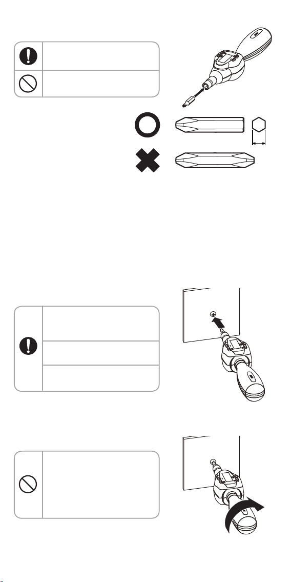
●Precautions for use of the driver type
■Mounting of a driver bit
For working procedures for disassembly and assembly of work objects and handling
of new parts, follow the maintenance instructions of each manufacturer, etc.
Injury and property damages may be caused.
Note
Note
● Do not extend the grip by
pipes, etc.
The main unit or other properties
may be damaged.
● Do not use the product for
any electrified work object.
Electric shock and property
damages may be caused.
●
For any high-place work, be sure to
implement safety measures.
Injury and property damages
may be caused.
●
Do not use the product out of the
specification range, e.g. overload.
Damages may be caused.
● Do not use any tip tool "at
an angle" or "with
insufficient engagement".
Injury and property damages
may be caused by slippage or
fall-off.
● Do not hit the main unit by
foot or strike it by a
hammer to give a shock.
Injury and damages of the main
unit or other properties may be
caused.
● Do not use the product in
an unstable place or at an
improper posture.
Injury and damages of the main
unit or other properties may be
caused.
● If any abnormal sound,
etc. occurs during work,
immediately stop working.
Injury and damages of the main
unit or other properties may be
caused.
● Do not use the product as
a chisel or lever.
Injury and damages of the main unit
or other properties may be caused.
Picture
indication
Important items Harm and damage
● Check for any crack or
damage on the tip tool.
Injury and damages of the main unit
or other properties may be caused.
● Do not swing around the
main unit
The main unit or other properties
may be damaged.
●
Use a driver bit appropriate
for respective conditions.
Damages may be caused.
Picture
indication
Important items Harm and damage

9
■Measurement
● Please use a driver bit
appropriate for the screw
size.
● Check the torque unit of the
work object.
● Insert the driver bit into the
screw to the end.
1. Set the product to the
object and work on it.
2. To measure the torque
value, grasp the grip and
apply a force slowly in the
working direction.
● Be sure to use a driver bit
with plane mounting surface.
● Double-head driver bit cannot
be used.
Attach a tip tool (driver bit, etc.) appropriate for the measurement object to
the dedicated adapter socket (magnetic attachment).
○ About tip tool
● Do not set the product to the
work object at an angle.
● Do not use ball point type tip
and universal joint.
● Do not joint multiple
extension bars.
Double-head bit
Single-head bit
6.3
Can be used
Cannot be used
Example: Measurement of
tightening torque
● Besides the supplied driver bit, our "bit for plate ratchet replacement
driver" (separately sold) may be attached.
● 6.3 sq. insert socket (KTC part number: B2) and bit socket (KTC part
number: BT2) may substitute the adapter socket with 6.3 sq. magnet.

10
Torque measurement
Injury and property damages may be caused.
■Overview of the torque measurement
○Measurement modes
There are three Measurement modes (measurement methods)
and three measurement value indication modes (indication
methods), which may be combined appropriately for usage.
If any work with a torque value within the specified range is
required, it is recommended to use the Preset mode or
Pass/Fail mode.
<Measurement modes>
1. Measurement mode (For details, refer to P. 11)
A mode to make a torque measurement without setting a
target torque value.
2. Preset mode (For details, refer to P. 12)
A mode convenient for continuous tightening works to a
target torque value.
• It is notified of by the light (LED lamp) and sound
(buzzer) that the target torque value is reached.
• Up to 5 target torque values can be set.
3. Pass/Fail mode (For details, refer to P. 15)
A mode to set lower and upper torque values and check
if the work is completed within the set torque value
range.
• The history (count) of accurate works can be logged.
<Measurement value indication modes>
1. Peak Hold Mode (For setting procedures, refer to P. 19)
Keep the maximum measurement value displayed.
● Do not apply any force out
of the indicated range.
Damages or malfunction may be
caused.
●
Do not apply any load on
the product when turning
the power ON.
Right torque measurement and
indication may be prevented.
●
Do not use the product with
any failure in indications of
torque measurement result
(damage on the display) not
eliminated.
The work object may be
damaged.
Picture
indication
Important items Harm and damage
Note

11
■How to use "Measurement mode"
The torque can be visually controlled without
setting a target torque. You may work on
while checking the tightening status.
Keep the main unit free from any force until "0" value is displayed on the
display after turning the power ON. Turning the power ON under any force
may cause wrong torque indication. After turning the power ON, make a
torque measurement with the ambient temperature stable. In places
where the temperature varies sharply, turn the power ON/OFF frequently.
When the Peak Hold mode is ON or no operation is on the way, a torque
value is kept indicated. However, the power is turned OFF after the time
set for the auto power OFF, which clears the measured torque value.
(Factory default: 2 minutes)
1. Turn the power ON.
Turn the power ON. Then the
starting-up indication
disappear and the
"Measurement mode" is
activated.
2. Check the display and
perform the work.
3. Once the measurement is
completed, a torque value
is indicated on the display.
The display indicates the
maximum measurement
value with the Peak Hold
mode.
(Default setting at the time of
shipment)
4. To clear the peak-hold
indication, press the
"+ (plus)/C (clear)" button.
5. Turn the power OFF.
Press and hold the "P" button
to turn the power OFF.
(About 3 seconds)
2. Auto Clear mode (For setting procedures, refer to P. 20)
A measurement value is displayed for the set time and
then the indication is reset to "0 (zero)".
(Adjustable between 1 to 10 seconds)
3. Track mode (For setting procedures, refer to P. 19)
A real-time torque value is indicated.
Press the "P" button
Indications in Measurement mode
(No-load condition)
Starting up
Blip!
Check

Display for target torque
value setting
When no set value is registered
Registration of target torque
Press and
hold
Set a target torque value
Blinking
Blip!
Memory number 2
Memory number 5
Memory number 1
Memory number 3
Memory number 4
Measurement Mode
Torque measurement
■Torque value setting in "Preset mode"
Preset torque values (settings) are convenient for frequent works and
repetitive works.
If "M" is blinking in the upper left
part of the display, the value
displayed in the memory number
and the value already registered
are not consistent.
○Recalling the set value
Recall the set value (memory number)
recorded in the Digital Ratchet main unit.
1. Turn the power ON.
2. Press the "M" button to
switch the memory
number display.
○
Registering a target torque value
A target torque value can be registered
with each memory number.
1. Display the memory
number.
Press the "M" button to
display a memory number to
be registered.
2. Display a target torque
value.
Press the "+ (plus/C (clear)"
and "- (minus)" buttons to
display a torque value to be
set.
3. Register.
Press and hold the "M"
button.
Registration is completed
with a short buzzer sound.
12
Display the memory number
Check

8
Display the memory number
13
Torque measurement
■How to use "Preset mode"
When the Peak Hold mode is ON or no operation is on the way, a
torque value is kept indicated. However, the power is turned OFF
after the time set for the auto power OFF, which clears the
measured torque value.
(Factory default: 2 minutes)
○Recalling the set value to
perform the work
Recall the set value (memory number)
recorded in the Digital Ratchet main unit to
perform the work.
1. Starting the "Preset mode"
Turn the power ON to enter
into the "Measurement
mode" and then press the
"M" button once.
Press the "M" button to
switch the Measurement
mode and memory numbers
1 through 5.
2. Checking the display
"M" lights in the upper left
part of the display and the
registered torque value is
indicated.
3. Measuring
It is ready for measurement
when "M" in the upper left
part of the display
disappears and "0 cN•m"
appears. When the value
approaches the set torque
value, the user is notified by
the buzzer and LED lighting.
4. Indicating the
measurement value
The display indicates the
maximum measurement
value with the Peak Hold
mode.
(Default setting at the time of shipment)
Lighting
pip pip pip
pip pip!
90% of the set torque value
Bleep!
Over the set torque value
Measurable
Check

14
Torque value
Time
Preset
upper limit
Preset
lower limit
Pass
Acceptance
range
Peak torque
Torque value
Time
Preset
upper limit
Preset
lower limit
Failure
Acceptance
range
Peak torque
■Setting of "Pass/Fail mode"
A function to check that the work is completed within the preset torque
range. The history (count) of whether a lot of bolts and nuts are accurately
worked on can be logged.
For custom settings, refer to P. 18
• For pass
It passes the criteria and counts as pass if the peak torque is within the set
torque value range.
• For failure
It fails the criteria and counts as failure if the peak torque is not within the set
torque value range.
○Enable the Pass/Fail mode
Enable the "Pass/Fail mode" in the
custom setting.
1. Turning the power OFF
2. Starting the custom
setting screen
Press and hold the "M"
button first and then press
the "P" button.
3. Checking that the setting
screen has been started
4. Pressing the "M" button to
switch the display
Set the mode indicator on
the display to "4".
Mode indicator
Setting screen
Setting screen
To use the Pass/Fail mode, it is necessary to enable the "Pass/Fail
mode" in the custom setting screen and set the "torque value acceptance
range (upper/lower limits)" and "measurement rotation direction
(right/left)".
Check

14
15
Pass/fail judgment clockwise rotation ON
Turn the power OFF
Pass/fail judgment
counterclockwise
rotation ON
Pass/fail judgment
Clockwise rotation ON
Pass/fail judgment
Counterclockwise rotation ON
Pass/fail judgment OFF
Mode indicator
Screen on start-up
Mode indicator
At the time of setting the lower limit value
Setting the torque value
Registering the
torque value
5.
Setting the "Pass/Fail mode"
Use the "+ (plus)/C (clear)"
and "- (minus)" buttons to
set the rotation direction for
the pass/fail judgment.
•Clockwise rotation ON : 4rOn
•Counterclockwise rotation ON : 4LOn
•No pass/fail judgment (OFF) : OFF
6. Setting completed
Press and hold the "P"
button (for about 3 seconds)
to turn the power OFF.
○
Setting the acceptance range
1. Turn the power ON.
2. Checking the display
Turning the power ON after
setting to the "Pass/Fail
mode" activates the
Pass/Fail mode and displays
"c" on the display.
"c" represents the count of
pass.
3. Setting the lower limit
value
Press the "M" button once
and check that "L" is
displayed in the mode
indicator on the display.
4. Displaying the lower limit
value
Use the "+ (plus)/C (clear)"
and "- (minus)" buttons to
display the specified lower
limit value.
5. Registering the lower limit
value
Press and hold the "M"
button (for about 2 seconds)
to register it.

16
○
Setting the acceptance range
6. Setting the upper limit
value
Press the "M" button twice
and check that "H" is
displayed in the mode
indicator on the display.
7. Displaying the upper limit
value
Use the "+ (plus)/C (clear)"
and "- (minus)" buttons to
display the specified upper
limit value.
8. Registering the upper limit
value
Press and hold the "M"
button (for about 2 seconds)
to register it.
■How to use "Pass/Fail mode"
1. Checking the display
After setting the upper and
lower limit values, check that
the mode indicator is "c".
2. Measurement
When torque measurement
starts, the mode indicator
part changes to "J" and the
torque value is indicated.
3. Pass/fail judgment
<Failure>
Lower limit value 90% to 99%
LED : Lighting
Buzzer sound : Intermittent
sound
Mode indicator
At the time of setting the upper limit value
Setting the torque value
Registering the
torque value
Target lower limit value
Target upper limit value
Pass counts of the pass/fail judgment
Mode indicator
In the Pass/Fail mode
Mode indicator
In the Pass/Fail mode measurement
Lower limit value 90% to 99%
pip pip pip
pip pip!

Bleep!
pip pip pip
pip pip!
Within the set torque range
Over 100% of the upper limit value
Mode indicator
3. Pass/fail judgment
<Pass>
Within the set torque range
LED : Lighting
Buzzer sound : Continuous
sound
<Failure>
Over 100% of the upper limit
value
LED : Lighting
Buzzer sound : Intermittent
sound
4. Indicating the
measurement value
The display indicates the
maximum measurement
value with the Peak Hold
mode.
(Default setting at the time of shipment)
5. To clear the peak-hold
indication, press the
"+ (plus)/C (clear)" button.
6. Indicating the pass count
The measurement value
disappears and the pass
count is indicated.
17

Press the "M" button.
Release the buttons at the
same time.
Press and hold the "M"
button and then press the
"P" button.
Press and hold at the
same time (for about 3
seconds)
18
Custom setting
By changing the Digital Ratchet settings, you can customize it for
your convenience.
○
Starting the custom setting screen
1. Press the "M" button
2. Pressing the "M" and "P"
buttons at the same time
Press the "M" button while
pressing and holding the "P"
button. (About 3 seconds)
3. Releasing the "M" and "P"
buttons
Release the buttons at the
same time.
4. Starting the setting screen
5. Changing the setting
Change the setting of each
item.
6. Turning the power OFF
After the setting, turn the
power OFF once with the
"P" button.
7. Turning the power ON
The setting change is
applied when the power is
back.
Item name
Setting at the
time of
shipment
Setting item Reference
page
Measurement
value
display method
P: Peak Hold mode
A: Auto Clear
t: Track mode
19
Auto clear time
(sec)
The measurement value is cleared
after the time set for the measurement
value indication method "A"
20
Buzzer sound
On: Buzzer is active
OFF: Mute 20
Pass/fail
judgment 21
Auto power OFF
time (min)
The power is turned OFF after the
specified period in an inactivity state
21
Measurement
unit
cN•m
N•m Switching of unit at the time of
measurement
22

Measurement value
indication methods
Press the "M" button
Peak Hold mode indication
(Setting at the time of shipment)
Auto clear time Buzzer sound
Pass/fail judgmentAuto power OFF timeMeasurement unit
Mode indicator
Auto Clear mode indication
Mode indicator
Track mode indication
Press and hold the "P" button
Mode indicator
19
○Navigation within the custom settings
Press the "M" button to navigate among setting items.
Settings can be changed in a row.
○Setting of the measurement
value indication method
1. Starting the custom
setting screen
(For startup procedures, refer to P. 18)
2. Navigating to the
measurement indication
method screen
Press the "M" button to
navigate to the mode
indicator "1".
3. Selecting an indication
method
Use the "+ (plus)/C (clear)"
and "- (minus)" buttons to
select a mode.
[P: Peak Hold mode]
Keep the maximum measurement
value to indicate it. The value is not
cleared until the "+ (plus)/C (clear)"
button is pressed.
[A: Auto Clear mode]
The measurement value is
displayed for the set time (second)
and automatically cleared.
[t: Track mode]
A real-time torque value is
indicated without keeping the
maximum measurement value.
4. Setting completed
Display a mode to change
and press and hold the "P"
button (for about 3 seconds)
to turn the power OFF.
This manual suits for next models
3
Table of contents
Other KTC Power Tools manuals