KTM 125 DUKE 2022 Manual

SETUP INSTRUCTIONS 2022
125 DUKE
Art. no. 3214687en


INTRODUCTION
*3214687en*
3214687en
03/2022
INTRODUCTION
Perform the work described in these setup instructions before the vehicle is delivered to the customer.
Read the setup instructions in their entirety before beginning work.
All specifications contained herein are non-binding. KTM Sportmotorcycle GmbH specifically reserves the right
to modify or delete technical specifications, prices, colors, forms, materials, services, designs, equipment, etc.,
without prior notice and without specifying reasons, to adapt these to local conditions, as well as to stop produc-
tion of a particular model without prior notice. KTM accepts no liability for delivery options, deviations from fig-
ures and descriptions, misprints, and other errors. The models portrayed partly contain special equipment that
does not belong to the regular scope of supply.
These setup instructions were written to correspond to the latest state of this model series. We reserve the right
to make modifications in the interest of technical advancement without at the same time updating these setup
instructions.
We shall not provide a description of general workshop methods. Likewise, safety rules that apply in a workshop
are not specified here. It is assumed that the work will be performed by a fully trained mechanic.
© 2022 KTM Sportmotorcycle GmbH, Mattighofen Austria
All rights reserved
Reproduction, even in part, as well as copying of all kinds, is permitted only with the express written permission
of the copyright owner.
ISO 9001(12 100 6061)
KTM applies quality assurance processes that lead to the highest possible product quality as
defined in the ISO 9001 international quality management standard.
Issued by: TÜV Management Service
KTM Sportmotorcycle GmbH
Stallhofnerstraße 3
5230 Mattighofen, Austria
This document is valid for the following models:
125 DUKE EU (F4003V1, F4003V2)
125 DUKE JP (F4086V3, F4086V4)
125 DUKE UK (F4022V1, F4022V2)

1 MEANS OF REPRESENTATION
2
1.1 Symbols used
The meaning of specific symbols is described below.
Indicates an expected reaction (e.g. of a work step or a function).
Indicates an unexpected reaction (e.g. of a work step or a function).
Indicates a page reference (more information is provided on the specified page).
Indicates information with more details or tips.
Indicates the result of a testing step.
Indicates a voltage measurement.
Indicates a current measurement.
Indicates a resistance measurement.
Indicates the end of an activity including potential rework.
1.2 Formats used
The typographical formats used in this document are explained below.
Proprietary name Indicates a proprietary name.
Name®Indicates a protected name.
Brand™ Indicates a brand available on the open market.
Underlined terms Refer to technical details of the vehicle or indicate technical terms, which
are explained in the glossary.

SETUP 2
3
2.1 Transport mode
H02713-01
This vehicle was blocked for transport in the software.
To operate the vehicle, the vehicle electronics must be enabled.
This process is conducted during initial setup in KTM Dealer.net.
Enabling ensures that the initial setup in KTM Dealer.net is docu-
mented.
Enabling can be performed either temporarily, e.g. for a test ride,
or permanently for vehicle handover.
Info
Make sure that the vehicle is permanently enabled before
handing it over to the customer.
2.2 Diagnostics connector
H01906-10
Diagnostics connector 1is located under the passenger seat.
2.3 Unpacking and setting up the vehicle
A00034-10
–Remove the straps and the box.
A00035-10
–Remove the adhesive tape in the upper area of the motorcycle.

2 SETUP
4
A00038-10
–Roll down the film at the sides.
Info
To avoid damaging the motorcycle during unpacking,
leave the other films on the vehicle until you have fin-
ished work on the vehicle.
–Remove the separate enclosure and unpack it. Check the sepa-
rate enclosure for completeness.
–Check the vehicle for transport damage.
A00037-10
Warning
Danger of accidents A repaired handlebar poses a
safety risk.
If the handlebar is bent or straightened, the mate-
rial becomes fatigued. The handlebar may break as a
result.
–Change the handlebar if the handlebar is damaged
or bent.
–Position the handlebar.
Info
Make sure the cables and wiring are positioned cor-
rectly.
–Position the handlebar clamp. Mount and tighten the screws
evenly.
Guideline
Screw, handle-
bar clamp
M8 20 Nm (14.8 lbf ft)
Loctite®243™
The lettering on the handlebar is in the middle of the han-
dlebar clamp.
A00036-10
–Position all controls in their exact positions on the handlebar.
Tighten all screws.
H03807-10
–Make sure that the clutch cable is attached to the clutch
release lever and secured.
–Check the clutch lever play. ( p. 7)
–Check the play in the throttle cable. ( p. 8)
–Mount and tighten the rear mirror on both sides.

SETUP 2
5
F01045-10
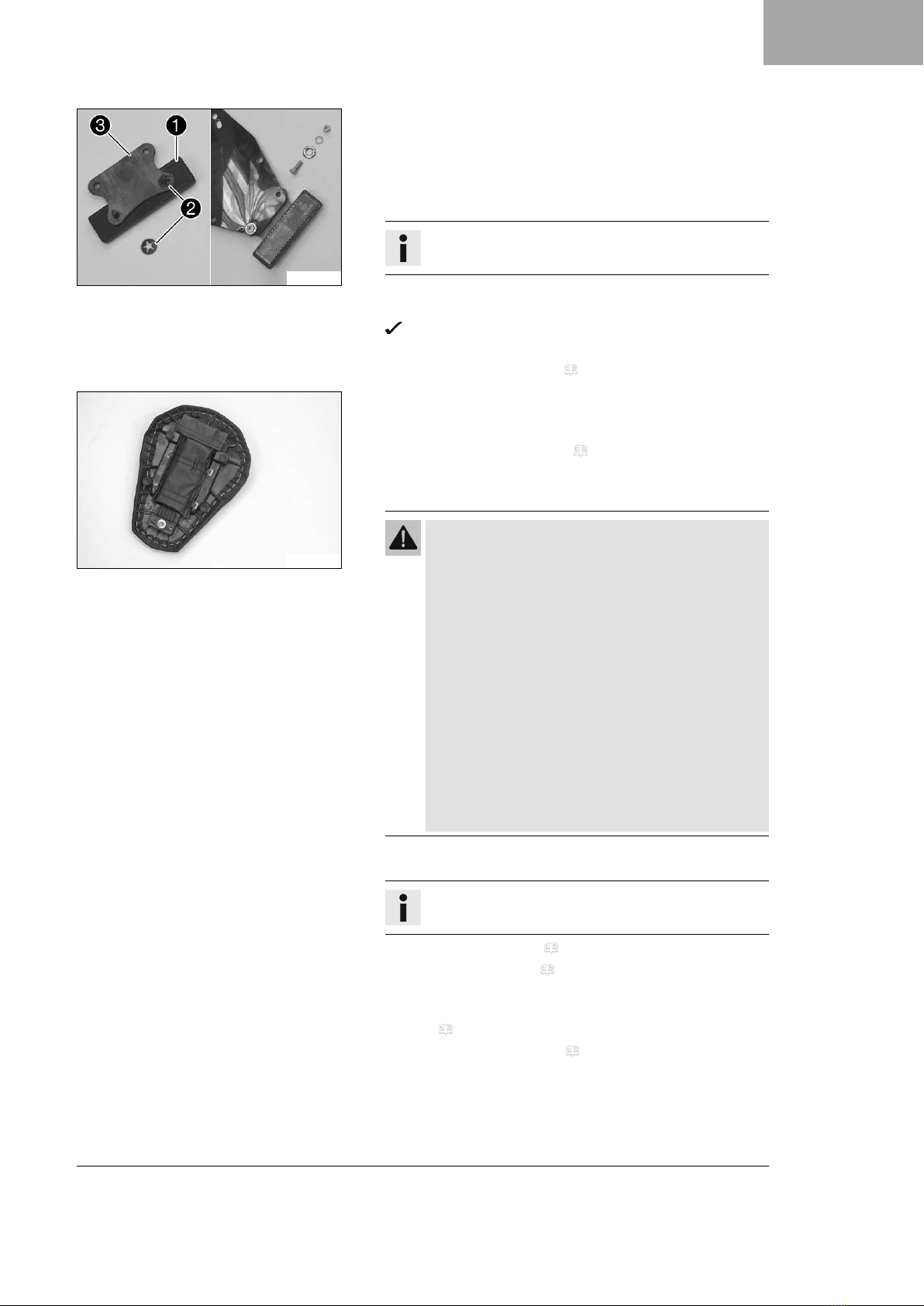
–Mount rear reflector 1with spring washers 2on holding
plate 3.
–Mount the retaining plate on the license plate holder.
–Mount the license plate holder.
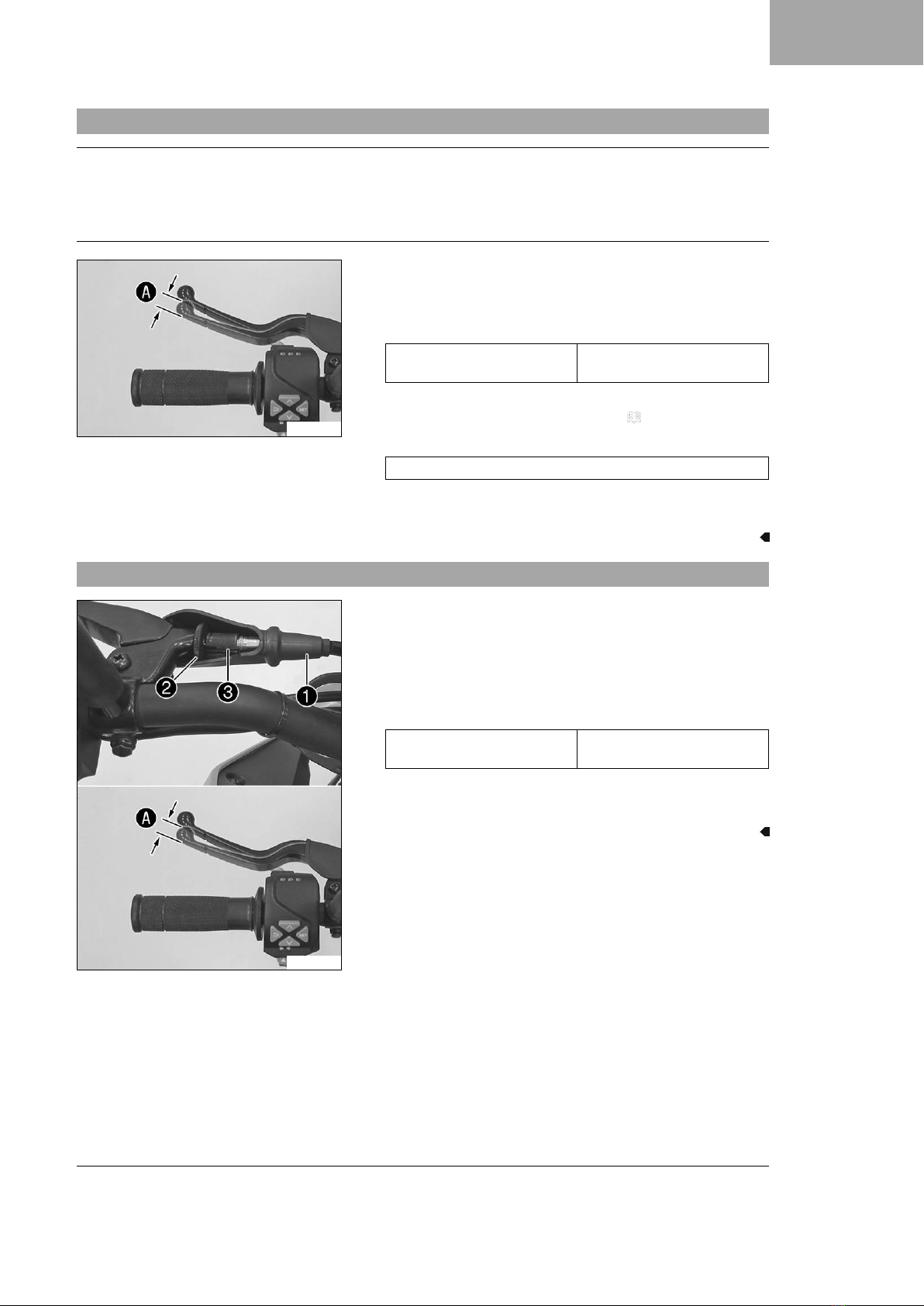
–Carefully loosen and remove the tension belt over the link fork.
Info
An assistant prevents the motorcycle from falling over.
–Carefully loosen and remove the tension belts around the lower
triple clamp.
The vehicle is released at the front.
–Together with an assistant, take the vehicle off the pallet.
–Remove the passenger seat. ( p. 8)
E01183-01
–Take tool set out of the separate enclosure and fasten onto the
bottom of the passenger seat using the rubber straps provided
in the tool set.
–Remove the front rider's seat. ( p. 9)
–Remove spare key and KEYCODECARD from under the seat and
keep in a safe place for the handover.
Warning
Risk of injury Battery acid and battery gases cause
serious chemical burns.
–Keep 12 V batteries out of the reach of children.
–Wear suitable protective clothing and safety
glasses.
–Avoid contact with battery acid and battery gases.
–Keep sparks or open flames away from the 12 V
battery.
–Only charge 12 V batteries in well-ventilated
rooms.
–Rinse the affected area immediately with plenty of
water in the event of contact with the skin.
–Rinse eyes with water for at least 15 minutes and
consult a doctor immediately if battery acid and
battery gases get into the eyes.
–Fill the 12 V battery.
Info
Read the notes in the 12 V battery accessory pack.
–Charge the 12-V battery. ( p. 10)
–Install the 12-V battery. ( p. 12)
–Remove the remaining film, padding, the corrugated card-
board, and the other packaging material.
–Refuel. ( p. 14)
–Check the headlight setting. ( p. 15)
–Prepare the vehicle according to the specifications in
the KTM Dealer.net for handover to the customer.

2 SETUP
6
Info
Transport mode must be deactivated to be able to start
the motorcycle.

WORK 3
7
3.1 Checking the clutch lever play
Note
Clutch damage If there is no free travel by the clutch lever, the clutch will begin to slip.
–Check the free travel of the clutch lever each time before using the motorcycle.
–Adjust the free travel of the clutch lever when necessary in accordance with the specification.
F00767-10
–Check the clutch lever for smooth operation.
–Move the handlebar to the straight-ahead position.
–Pull the clutch lever until resistance is perceptible, and deter-
mine the play in the clutch lever A.
Clutch lever play A1 … 3 mm (0.04 …
0.12 in)
» If the clutch lever play does not meet the specified value:
–Adjust play in the clutch lever. ( p. 7)
–Move the handlebar to and fro over the entire steering range.
The clutch lever play must not change.
» If the clutch lever play changes:
–Check the routing of the clutch cable.
3.2 Adjusting play in the clutch lever
F00768-10
–Move the handlebar to the straight-ahead position.
–Push back sleeve 1.
–Loosen lock nut 2.
–Adjust the play in the clutch level Aby turning adjusting
screw 3.
Guideline
Clutch lever play A1 … 3 mm (0.04 …
0.12 in)
–Tighten lock nut 2.
–Position bellows 1.

3 WORK
8
3.3 Checking the play in the throttle cable
400192-11
–Check the throttle grip for smooth operation.
–Move the handlebar to the straight-ahead position. Turn the
throttle grip back and forth slightly and determine the play in
throttle cable A.
Throttle cable play A3 … 5 mm (0.12 … 0.2 in)
» If the throttle cable play does not meet the specified value:
–Adjust the play in the throttle cable. ( p. 8)
Danger
Danger of poisoning Exhaust gases are toxic and inhal-
ing them may result in unconsciousness and death.
–Always make sure there is sufficient ventilation
when running the engine.
–Use effective exhaust extraction when starting or
running the engine in an enclosed space.
–Start the engine and let it run at idle speed. Move the handle-
bar to and fro over the entire steering range.
The idle speed must not change.
» If the idle speed changes:
–Check the throttle cable routing.
3.4 Adjusting the play in the throttle cable
F00773-10
–Move the handlebar to the straight-ahead position.
–Push back sleeve 1.
–Loosen lock nut 2.
–Adjust the play in the throttle cable by turning barrel
adjuster 3.
Guideline
Play in throttle cable 3 … 5 mm (0.12 … 0.2 in)
–Tighten lock nut 2.
–Slide on sleeve 1.
3.5 Removing the passenger seat
H01991-10
–Insert the ignition key in seat lock 1and turn it clockwise.
–Raise the rear of the seat, push it towards the rear, and lift it
off.
–Remove the ignition key from the seat lock.

WORK 3
9
3.6 Mounting the passenger seat
H01992-01
–Attach hooks 1on the passenger seat to seat mounting 2
on the subframe, and lower it at the rear while pushing for-
ward.
–Press the passenger seat downward until it clicks into place.
Warning
Danger of accidents The seat can come loose from the
anchoring if it is not mounted correctly.
–After assembly, check whether the seat is correctly
locked and cannot be pulled up.
–Finally, check that the passenger seat is correctly mounted.
3.7 Removing the front rider's seat
Preparatory work
–Remove the passenger seat. ( p. 8)
H01993-01
Main work
–Raise the rear of the front rider's seat, pull it towards the rear,
and remove it upwards.
3.8 Mounting the front rider's seat
H01994-01
Main work
–Attach the front rider's seat in area Aand lower at the rear.
–Finally, check that the front rider's seat is correctly mounted.
Finishing work
–Mount the passenger seat. ( p. 9)

3 WORK
10
3.9 Disconnecting the negative cable of the 12-V battery
Preparatory work
–Remove the passenger seat. ( p. 8)
–Remove the front rider's seat. ( p. 9)
V01273-10
Main work
–Disconnect negative cable 1of the 12-V battery.
3.10 Connecting the negative cable of the 12-V battery
V01273-10
Main work
–Connect negative cable 1of the 12-V battery.
Finishing work
–Mount the front rider's seat. ( p. 9)
–Mount the passenger seat. ( p. 9)
–Set time and date. ( p. 12)
3.11 Charging the 12-V battery
Warning
Risk of injury Battery acid and battery gases cause serious chemical burns.
–Keep 12 V batteries out of the reach of children.
–Wear suitable protective clothing and safety glasses.
–Avoid contact with battery acid and battery gases.
–Keep sparks or open flames away from the 12 V battery.
–Only charge 12 V batteries in well-ventilated rooms.
–Rinse the affected area immediately with plenty of water in the event of contact with the skin.
–Rinse eyes with water for at least 15 minutes and consult a doctor immediately if battery acid and
battery gases get into the eyes.
Note
Danger of damage An incorrectly selected charging mode will damage the 12-V battery.
–Always select a charging mode that is compatible with the type of battery.

WORK 3
11
Note
Environmental hazard 12 V batteries contain environmentally hazardous materials.
–Do not dispose of 12 V batteries as household waste.
–Dispose of 12 V batteries at a collection point for used batteries.
Note
Environmental hazard Hazardous substances cause environmental damage.
–Dispose of oils, grease, filters, fuel, cleaning agents, brake fluid, etc., correctly and in compliance with
the applicable regulations.
Info
Even when there is no load on the 12-V battery, it discharges steadily each day.
The charging level and the method of charging are very important for the service life of the 12-V battery.
Rapid recharging with a high charging current shortens the service life of the battery.
If the charging current, charging voltage, or charging time is exceeded, electrolyte escapes through the
safety valves. This reduces the capacity of the 12-V battery.
If the 12-V battery is depleted by repeated starting, the 12-V battery must be charged immediately.
If the 12-V battery is left in a discharged state for an extended period, it will become deeply discharged
and sulfating occurs, destroying the battery.
The 12-V battery is maintenance-free. The acid level does not have to be checked.
Preparatory work
–Remove the passenger seat. ( p. 8)
–Remove the front rider's seat. ( p. 9)
–Disconnect the negative cable of the 12-V battery. ( p. 10)
311910-10
Main work
–Connect a battery charger to the 12-V battery. Adjust the bat-
tery charger.
EU battery charger XCharge‑professional (00029095050)
Alternative 1
US battery charger XCharge‑professional
(00029095051)
Alternative 2
UK battery charger XCharge‑professional
(00029095052)
Info
Follow the instructions of the charger and the manual.
–Disconnect the battery charger after charging the 12-V battery.
Guideline
The charging current, charging voltage, and charging time
must not be exceeded.
Recharge the 12-V battery
regularly when the motorcy-
cle is not being used
3 months
Finishing work
–Connect the negative cable of the 12-V battery. ( p. 10)
–Mount the front rider's seat. ( p. 9)
–Mount the passenger seat. ( p. 9)
–Set time and date. ( p. 12)

3 WORK
12
3.12 Installing the 12-V battery
V01274-11
Main work
–Position the 12-V battery in the battery compartment.
12-V battery (ETZ-9-BS)
–Attach rubber strap 1.
–Position positive cable 2and mount and tighten the screw.
–Position positive terminal cover 3.
V01273-11
–Position negative cable 4and mount and tighten the screw.
Finishing work
–Mount the front rider's seat. ( p. 9)
–Mount the passenger seat. ( p. 9)
–Set time and date. ( p. 12)
3.13 Setting the time and date
Condition
The motorcycle is stationary.
S05084-01
–Press the SET button when the menu is closed.
–Press UP or DOWN button until Settings appears. Press
the SET button to open the menu.
–Press the UP or DOWN button until Time/Date is highlighted.
Press the SET button to open the menu.
S05085-01
Setting the clock
–Press UP or DOWN button until the time is marked.
–Press the SET button.
The hour flashes and is underlined.
–Press UP or DOWN button until the current hour is set.
–Press the SET button.
The minutes flash and are underlined.
–Press UP or DOWN button until the current minute is set.
–Press the SET button.
The time is stored.

WORK 3
13
S05086-01
Setting the date
–Press UP or DOWN button until the date is marked.
–Press the SET button.
The day flashes and is underlined.
–Press UP or DOWN button until the current day is set.
–Press the SET button.
The month flashes and is underlined.
–Press UP or DOWN button until the current month is set.
–Press the SET button.
The year flashes and is underlined.
–Press UP or DOWN button until the current year is set.
–Press the SET button.
The date is stored.
3.14 Opening fuel tank filler cap
Danger
Fire hazard Fuel is highly flammable.
The fuel in the fuel tank expands when warm and can escape if overfilled.
–Do not fuel the vehicle in the vicinity of open flames or lit cigarettes.
–Switch off the engine for refueling.
–Make sure that no fuel is spilled; particularly not on hot parts of the vehicle.
–If any fuel is spilled, wipe it off immediately.
–Observe the specifications for refueling.
Warning
Danger of poisoning Fuel is poisonous and a health hazard.
–Avoid skin, eye and clothing contact with fuel.
–Immediately consult a doctor if you swallow fuel.
–Do not inhale fuel vapors.
–In case of skin contact, rinse the affected area with plenty of water.
–Rinse the eyes thoroughly with water, and consult a doctor in case of fuel contact with the eyes.
–Change your clothing in case of fuel spills on them.
–Keep fuels correctly in a suitable canister, and out of the reach of children.
Note
Environmental hazard Improper handling of fuel is a danger to the environment.
–Do not allow fuel to enter the groundwater, the soil, or the sewage system.
F00874-10
–Lift cover 1of the fuel tank filler cap and insert the ignition
key into the lock.
Note
Danger of damage The ignition key may break if overloaded.
Damaged ignition keys must be replaced.
–Push down on the fuel tank filler cap to take pressure off
the ignition key.
–Turn the ignition key 90° clockwise.
–Lift the fuel tank filler cap.

3 WORK
14
–Remove the ignition key.
3.15 Closing the fuel tank filler cap
F00875-01
Warning
Fire hazard Fuel is highly flammable, toxic and a
health hazard.
–Check that the fuel tank filler cap is locked cor-
rectly after closing.
–Change your clothing if fuel spills on them.
–Rinse the affected area immediately with plenty of
water in the event of contact with the skin.
–Close the fuel tank filler cap.
–Push down the fuel tank filler cap until the lock engages.
3.16 Refueling
Danger
Fire hazard Fuel is highly flammable.
The fuel in the fuel tank expands when warm and can escape if overfilled.
–Do not fuel the vehicle in the vicinity of open flames or lit cigarettes.
–Switch off the engine for refueling.
–Make sure that no fuel is spilled; particularly not on hot parts of the vehicle.
–If any fuel is spilled, wipe it off immediately.
–Observe the specifications for refueling.
Warning
Danger of poisoning Fuel is poisonous and a health hazard.
–Avoid skin, eye and clothing contact with fuel.
–Immediately consult a doctor if you swallow fuel.
–Do not inhale fuel vapors.
–In case of skin contact, rinse the affected area with plenty of water.
–Rinse the eyes thoroughly with water, and consult a doctor in case of fuel contact with the eyes.
–Change your clothing in case of fuel spills on them.
Note
Material damage Inadequate fuel quality causes the fuel filter to quickly become clogged.
In some countries and regions, the available fuel quality and cleanliness may not be sufficient. This will result in
problems with the fuel system.
–Refuel only with clean fuel that meets the specified standards.
Note
Environmental hazard Improper handling of fuel is a danger to the environment.
–Do not allow fuel to enter the groundwater, the soil, or the sewage system.

WORK 3
15
V01517-10
–Switch off the engine.
–Open the fuel tank filler cap. ( p. 13)
–Fill the fuel tank with fuel up to the lower edge 1of the fuel
filler.
Total fuel tank
capacity, approx.
11 l
(2.9 US gal)
Super unleaded
(ROZ 95)
( p. 20)
–Close the fuel tank filler cap. ( p. 14)
3.17 Checking the headlight setting
400726-10
–Park the vehicle on a horizontal surface in front of a light-
colored wall and make a mark at the height of the center of
the low beam headlight.
–Make another mark at a distance Bunder the first marking.
Guideline
Distance B5 cm (2 in)
–Position the vehicle vertical to the wall at distance Afrom
the wall and switch on the low beam.
Guideline
Distance A5 m (16 ft)
–The rider now mounts the motorcycle with luggage and passen-
ger if applicable.
–Check the headlight setting.
The light-dark boundary must be exactly on the lower mark-
ing when the motorcycle is ready to be operated with the
rider mounted along with any luggage and a passenger if
applicable.
» If the boundary between light and dark does not meet
specifications:
–Adjust the headlight range. ( p. 16)

3 WORK
16
3.18 Adjusting the headlight range
Preparatory work
–Check the headlight setting. ( p. 15)
F00850-10
Main work
–Turn adjusting screw 1to adjust the headlight range.
Info
Turn clockwise to increase the headlight range; turn
counterclockwise to reduce the headlight range.
If you have a payload, you may have to correct the
headlight range.
Screw 1also secures the headlight. Ensure the screw
is always screwed in far enough.
400726-11
–Set the headlight to marking B.
Guideline
The light-dark boundary must lie exactly on lower mark-
ing Bwhen the motorcycle is ready to operate with the
rider mounted along with any luggage and a passenger if
applicable.

TECHNICAL DATA 4
17
4.1 Chassis tightening torques
Screw, chain guard EJOT PT®K60x30 7 Nm (5.2 lbf ft)
Remaining screws, chassis M4 4 Nm (3 lbf ft)
Remaining nuts, chassis M5 5 Nm (3.7 lbf ft)
Remaining screws, chassis M5 5 Nm (3.7 lbf ft)
Screw, chain guard M5 7 Nm (5.2 lbf ft)
Loctite®243™
Screw, compensating tank cap
lock, rear brake
M5 9 Nm (6.6 lbf ft)
Screw, fuel tank cover M5 4 Nm (3 lbf ft)
Screw, outer clutch cable guide M5 5 Nm (3.7 lbf ft)
Screw, side stand sensor M5 5 Nm (3.7 lbf ft)
Loctite®243™
Screw, tail light M5 5 Nm (3.7 lbf ft)
Nut, foot brake lever adjustment M6 9 Nm (6.6 lbf ft)
Remaining nuts, chassis M6 10 Nm (7.4 lbf ft)
Remaining screws, chassis M6 10 Nm (7.4 lbf ft)
Screw, ABS hose clamp M6 7 Nm (5.2 lbf ft)
Screw, ABS module M6 10 Nm (7.4 lbf ft)
Screw, ABS module retaining
bracket on frame
M6 7 Nm (5.2 lbf ft)
Screw, air filter box M6 6 Nm (4.4 lbf ft)
Screw, brake fluid reservoir for rear
brake
M6 8 Nm (5.9 lbf ft)
Screw, brake hose clamp M6 7 Nm (5.2 lbf ft)
Screw, chain sliding guard M6 7 Nm (5.2 lbf ft)
Screw, combination instrument M6 7 Nm (5.2 lbf ft)
Screw, compensating tank M6 5 Nm (3.7 lbf ft)
Screw, damper block M6 8 Nm (5.9 lbf ft)
Screw, engine sprocket cover M6 8 Nm (5.9 lbf ft)
Screw, foot brake cylinder M6 9 Nm (6.6 lbf ft)
Loctite®243™
Screw, front fender M6 7 Nm (5.2 lbf ft)
Screw, front seat fixing M6 6 Nm (4.4 lbf ft)
Screw, front spoiler M6x13 9 Nm (6.6 lbf ft)
Screw, front spoiler rear M6x9 9 Nm (6.6 lbf ft)
Screw, fuel pump M6 10 Nm (7.4 lbf ft)
Screw, headlight M6 8 Nm (5.9 lbf ft)
Screw, ignition coil M6 8 Nm (5.9 lbf ft)
Screw, ignition lock (tamper-proof
screw)
M6 13 Nm (9.6 lbf ft)
Screw, license plate holder M6 12 Nm (8.9 lbf ft)
Loctite®243™
Screw, lower rear panel M6 7 Nm (5.2 lbf ft)
Screw, magnetic holder on side
stand
M6 5 Nm (3.7 lbf ft)
Loctite®243™
Screw, main silencer M6 12 Nm (8.9 lbf ft)

4 TECHNICAL DATA
18
Screw, main silencer retaining
bracket
M6 9 Nm (6.6 lbf ft)
Screw, protective plate M6 8 Nm (5.9 lbf ft)
Screw, radiator holder M6 10 Nm (7.4 lbf ft)
Screw, radiator shield M6 7 Nm (5.2 lbf ft)
Screw, rear splash protector M6 9 Nm (6.6 lbf ft)
Screw, shift lever linkage M6 11 Nm (8.1 lbf ft)
Loctite®243™
Screw, side stand sensor cable
holder
M6 9 Nm (6.6 lbf ft)
Loctite®243™
Screw, tilt sensor M6 8 Nm (5.9 lbf ft)
Screw, wheel speed sensor holder M6 8 Nm (5.9 lbf ft)
Screw, wheel speed sensor of rear
wheel
M6 8 Nm (5.9 lbf ft)
Loctite®243™
Nut, rear sprocket M8 27 Nm (19.9 lbf ft)
Loctite®243™
Remaining nuts, chassis M8 25 Nm (18.4 lbf ft)
Remaining screws, chassis M8 25 Nm (18.4 lbf ft)
Screw, bottom triple clamp M8 12 Nm (8.9 lbf ft)
Screw, engine bearer M8 22 Nm (16.2 lbf ft)
Screw, foot brake lever M8 16 Nm (11.8 lbf ft)
Loctite®243™
Screw, fork stub M8 15 Nm (11.1 lbf ft)
Screw, front brake disc M8 30 Nm (22.1 lbf ft)
Loctite®243™
Screw, front seat fixing M8 20 Nm (14.8 lbf ft)
Screw, front wheel spindle M8 25 Nm (18.4 lbf ft)
Screw, fuel tank M8 20 Nm (14.8 lbf ft)
Screw, grab handle M8 22 Nm (16.2 lbf ft)
Screw, handlebar clamp M8 20 Nm (14.8 lbf ft)
Loctite®243™
Screw, horn M8 12 Nm (8.9 lbf ft)
Screw, lower rear panel M8 15 Nm (11.1 lbf ft)
Loctite®243™
Screw, main silencer M8 23 Nm (17 lbf ft)
Screw, passenger footrest unit M8 22 Nm (16.2 lbf ft)
Loctite®243™
Screw, rear brake disc M8 21 Nm (15.5 lbf ft)
Loctite®243™
Screw, rear seat fixing M8 18 Nm (13.3 lbf ft)
Screw, seat support plate M8 18 Nm (13.3 lbf ft)
Screw, subframe M8 25 Nm (18.4 lbf ft)
Loctite®620™
Screw, top triple clamp M8 15 Nm (11.1 lbf ft)
Screw, front brake caliper M8x1 30 Nm (22.1 lbf ft)
Loctite®243™
Banjo bolt, brake line M10 24 Nm (17.7 lbf ft)
Other manuals for 125 DUKE 2022
1
Table of contents
Other KTM Motorcycle manuals

KTM
KTM 1190 RC8 R EU/UK 2009 User manual

KTM
KTM 1190 Adventure R EU User manual

KTM
KTM EXC 200 EXC User manual

KTM
KTM 350 SX-F EU 2014 Manual

KTM
KTM 350 SX-F 2021 User manual

KTM
KTM 350 EXC-F EU 2013 User manual

KTM
KTM 690 Duke 2018 User manual

KTM
KTM 690 SMC R EU 2015 User manual

KTM
KTM 990 SUPER DUKE User manual

KTM
KTM 125 SX User guide

KTM
KTM 390 ADVENTURE 2022 Manual

KTM
KTM 450 EXC-F 2022 Manual

KTM
KTM 250 XC-F 2017 Manual

KTM
KTM 1290 Super Duke GT 2018 Manual

KTM
KTM 65 SX 2018 User manual

KTM
KTM 65 SX 1999 User manual

KTM
KTM 65 XC 2009 User manual

KTM
KTM 125 DUKE 2021 User manual

KTM
KTM 1190 RC8 R EU/UK 2009 User manual

KTM
KTM 350 SX-F Cairoli replica User manual