KTM 640 DUKE II 2001 User guide

OWNERS HANDBOOK
2001
BEDIENUNGSANLEITUNG
640 DUKE II
Art.Nr. 3.205.99 11/2000


ENGLISH
1
IMPORTANT
WE STRONGLY SUGGEST THAT YOU READ THIS MANUAL
CAREFULLY AND COMPLETELY BEFORE GOING ON YOUR FIRST
RIDE. IT CONTAINS A GREAT DEAL OF INFORMATION AND
ADVICE WHICH WILL HELP YOU USE AND HANDLE YOUR BIKE
PROPERLY. IN YOUR OWN INTEREST, PLEASE PAY PARTICULAR
ATTENTION TO NOTICES THAT ARE MARKED AS FOLLOWS:
WARNING
IGNORING THESE INSTRUCTIONS, CAN ENDANGER YOUR
BODY AND YOUR LIFE.
!
CAUTION
!
IGNORING THESE INSTRUCTIONS COULD CAUSE DAMAGE TO
PARTS OF YOUR MOTORCYCLE OR THAT THE MOTORCYCLE
IS NOT ROAD-SAFE ANYMORE.
Please insert the series numbers of your motorcycle in the boxes below
Cassis number
Engine number
Stamp of dealer
COMSUMER INFORMATION FOR AUSTRALIA ONLY
TAMPERING WITH NOISE CONTROL SYSTEM PROHIBITED
Owners are warned that the law may prohibit:
(a)
The removal or rendering inoperative by any person other than for purposes of maintenance, repair
or replacement, of any device or element of design incorporated into any new vehicle for the pur-
pose of noise control prior to its sale or delivery to the ultimate purchaser or while it is in use; and
(b) the use of the vehicle after such device or element of design has been removed or rendered
inoperative by any person.
KTM S
PORTMOTORCYCLE
AG
RESERVES THE RIGHT TO MODIFY ANY EQUIPMENT
,
TECHNICAL SPECIFICATIONS
,
COLORS
,
MATERIALS
,
SERVICES OFFERED AND RENDERED
,
AND THE LIKE SO AS TO ADAPT THEM TO LOCAL CONDITIONS WITHOUT
PREVIOUS ANNOUNCEMENT AND WITHOUT GIVING REASONS
,
OR TO CANCEL ANY OF THE ABOVE ITEMS WITHOUT SUBSTI
-
TUTING THEM WITH OTHERS
. I
T SHALL BE ACCEPTABLE TO STOP MANUFACTURING A CERTAIN MODEL WITHOUT PREVIOUS
ANNOUNCEMENT
. I
N THE EVENT OF SUCH MODIFICATIONS
,
PLEASE ASK YOUR LOCAL
KTM
DEALER FOR INFORMATION
.
W
E SHALL NOT BE HELD LIABLE FOR ANY PRINTING ERRORS
.

ENGLISH
2
Introduction
We would like to congratulate you on your purchase of a KTM motorcycle. Let us also take this
opportunity to thank you for putting your trust in us; we will not let you down.
You are now owner of a sporty and modern motorcycle which you are bound to have a great time
with provided you care for it properly. Before going for a first ride on your motorbike, you should
read this Owner’s Handbook carefully, even if this takes some of your precious time, so as to
familiarize yourself with how your motorbike is to be operated and which features it offers you.
Only by doing so will you learn how you can best tune your motorcycle to your needs and how
you can avoid bodily injuries. In addition, this Owner’s Handbook contains invaluable informa-
tion about motorcycle maintenance. At the time of printing, this User's Guide corresponded to the
latest state of this model family. It is, however, possible that we may have made slight modificati-
ons in the meantime due to development in our motorcycle design.
The Owner’s Handbook is an essential part of the motorbike and should - when the bike is sold -
be handed over to the new owner.
Many motorcyclists have a good working knowledge of motorcycle mechanics; if this is true in
your case, you will be able to use this Owner’s Handbook to carry out most of the maintenance
steps yourself. If, on the other hand, you are not very familiar with motorcycles, it might be better
to have a professional KTM dealer perform those steps marked by *found in the chapter entitled
“Maintenance Work on Chassis and Engine” of this manual.
Take special care to follow the recommended run in, inspection, and maintenance
intervals. Heeding these guidelines will significantly increase the life of your motorcycle. Be sure to
have any maintenance jobs performed by an authorized KTM dealer.
Address your special requests to an authorized KTM dealer who, should the need arise, will be
supported by the KTM importer.
Please do not forget to don your helmet, eye protection, and protective clothing when going for a
ride. KTM riders are responsible riders! We wish you a lot of fun when driving !
KTM SPORTMOTORCYCLE AG
5230 MATTIGHOFEN, AUSTRIA
ALL RIGHTS RESERVED TO MAKE ALTERATIONS TO DESIGN AND MODEL.
©by KTM SPORTMOTORCYCLE AG, AUSTRIA All rights reserved
KTM Austria’s certificate of achievement for its Quality
System ISO 9001 is the beginning of an on-going total
re-engineering quality plan for a brighter tomorrow.

ENGLISH
3
Page
IMPORTANT NOTES . . . . . . . . . . . . . . . . . . . . . . . . . . . . . .1
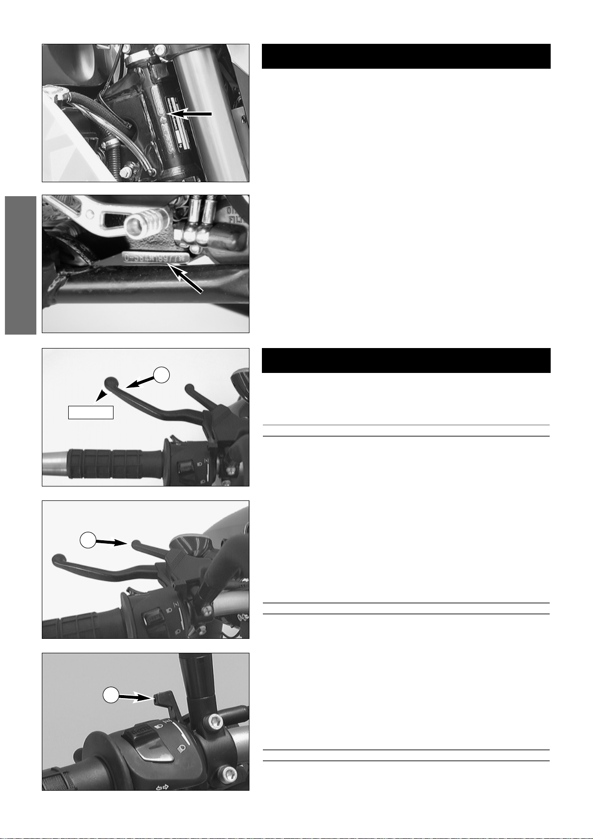
SERIAL NUMBER LOCATING . . . . . . . . . . . . . . . . . . . . . . .4
Cassis number . . . . . . . . . . . . . . . . . . . . . . . . . . . . . . . . .4
Engine number, engine type . . . . . . . . . . . . . . . . . . . . . .4
OPERATION INSTRUMENTS . . . . . . . . . . . . . . . . . . . . . . .4
Clutch lever . . . . . . . . . . . . . . . . . . . . . . . . . . . . . . . . . . .4
Hand decompression lever . . . . . . . . . . . . . . . . . . . . . . .4
Choke lever . . . . . . . . . . . . . . . . . . . . . . . . . . . . . . . . . . .4
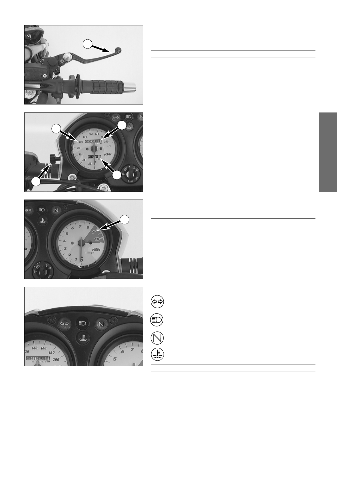
Hand brake lever . . . . . . . . . . . . . . . . . . . . . . . . . . . . . . .5
Speedometer . . . . . . . . . . . . . . . . . . . . . . . . . . . . . . . . . .5
Tachometer . . . . . . . . . . . . . . . . . . . . . . . . . . . . . . . . . . .5
Indicator lamps . . . . . . . . . . . . . . . . . . . . . . . . . . . . . . . .5
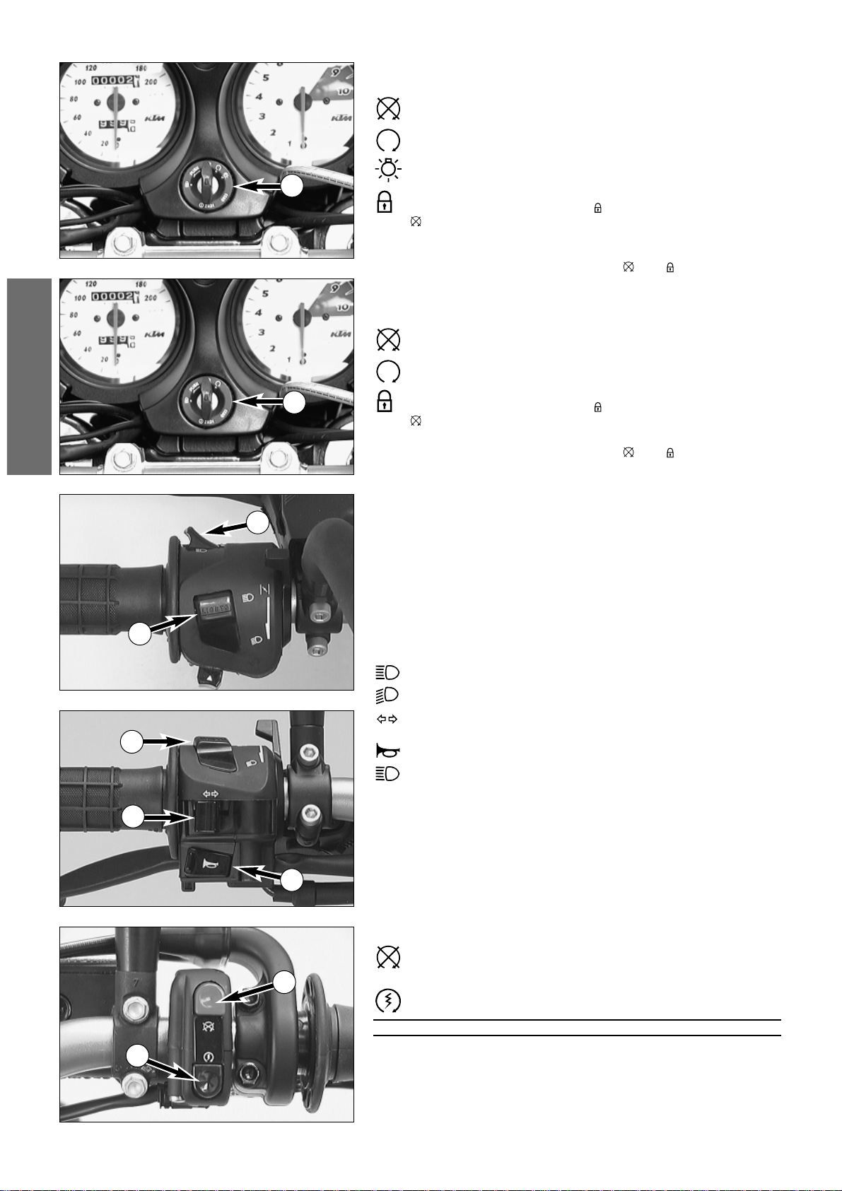
Ignition lock, with 4 switch position . . . . . . . . . . . . . . . .6
Ignition lock with 3 switch position . . . . . . . . . . . . . . . . .6
Combination switch . . . . . . . . . . . . . . . . . . . . . . . . . . . .6
Emergency OFF button . . . . . . . . . . . . . . . . . . . . . . . . . .6
Emergency OFF switch . . . . . . . . . . . . . . . . . . . . . . . . . .7
Filler cap . . . . . . . . . . . . . . . . . . . . . . . . . . . . . . . . . . . . .7
Fuel . . . . . . . . . . . . . . . . . . . . . . . . . . . . . . . . . . . . . . . . .7
Fuel tap . . . . . . . . . . . . . . . . . . . . . . . . . . . . . . . . . . . . . .7
Shift lever . . . . . . . . . . . . . . . . . . . . . . . . . . . . . . . . . . . .8
Kickstarter . . . . . . . . . . . . . . . . . . . . . . . . . . . . . . . . . . . .8
Foot brake pedal . . . . . . . . . . . . . . . . . . . . . . . . . . . . . . .8
Compression damping of fork . . . . . . . . . . . . . . . . . . . . .8
Rebound damping of fork . . . . . . . . . . . . . . . . . . . . . . . .8
Compression damping of shock absorber . . . . . . . . . . . .9
Rebound damping of shock absorber . . . . . . . . . . . . . . .9
Seat lock . . . . . . . . . . . . . . . . . . . . . . . . . . . . . . . . . . . . .9
Supporting strap for the passenger . . . . . . . . . . . . . . . . .9
DRIVING INSTRUCTIONS . . . . . . . . . . . . . . . . . . . . . . . . .10
LUBRICATION AND MAINTENANCE SCHEDULE . . . . . . .14
MAINTENANCE WORK ON CHASSIS AND ENGINE . . . . .16
Tool kit . . . . . . . . . . . . . . . . . . . . . . . . . . . . . . . . . . . . . . .16
Checking and adjusting the steering head bearing . . . . . . .16
Changing the spring preload of the shock absorber . . . . . .17
Checking the rubber ring on the shock absorber . . . . . . . .17
Lubricate rear shock absorber linkage . . . . . . . . . . . . . . . .17
Checking chain tension . . . . . . . . . . . . . . . . . . . . . . . . . . .18
Correcting chain tension . . . . . . . . . . . . . . . . . . . . . . . . . .18
Chain wear . . . . . . . . . . . . . . . . . . . . . . . . . . . . . . . . . . . .18
Chain maintenance . . . . . . . . . . . . . . . . . . . . . . . . . . . . . .19
Maintaining chain tension eccentrics . . . . . . . . . . . . . . . . .19
General information about KTM disc brakes . . . . . . . . . . .19
Changing the basic position of the handbrake lever . . . . . .20
Page
Checking of brake fluid level - front brake . . . . . . . . . .20
Refilling the front brake fluid reservoir . . . . . . . . . . . . .20
Checking the front brake pads . . . . . . . . . . . . . . . . . . .21
Changing the basic position of the brake pedal . . . . . . .21
Checking the rear brake fluid level . . . . . . . . . . . . . . . .21
Refilling the rear brake fluid reservoir . . . . . . . . . . . . . .21
Checking the rear brake pads . . . . . . . . . . . . . . . . . . . .22
Dismounting and mounting the front wheel . . . . . . . . .22
Dismounting and mounting the rear wheel . . . . . . . . . .22
Checking the damping rubbers in the rear wheel
. . . .23
Tires, air pressure . . . . . . . . . . . . . . . . . . . . . . . . . . . . .24
Battery . . . . . . . . . . . . . . . . . . . . . . . . . . . . . . . . . . . . .24
Charging the battery . . . . . . . . . . . . . . . . . . . . . . . . . . .24
Main fuse . . . . . . . . . . . . . . . . . . . . . . . . . . . . . . . . . . .25
Fuses for indivitual power-consuming units . . . . . . . . . .25
Opening the head light mask . . . . . . . . . . . . . . . . . . . .25
Headlight range adjustment . . . . . . . . . . . . . . . . . . . . .26
Headlight - replacing the bulbs . . . . . . . . . . . . . . . . . . .26
Parking light - replacing the bulb . . . . . . . . . . . . . . . . .26
Flasher - replacing the bulbs . . . . . . . . . . . . . . . . . . . . .26
Stop light and tail light - replacing bulb . . . . . . . . . . . . .27
Cooling system . . . . . . . . . . . . . . . . . . . . . . . . . . . . . . .27
Checking the coolant level . . . . . . . . . . . . . . . . . . . . . .28
Adjusting the clutch cable . . . . . . . . . . . . . . . . . . . . . . .28
Checking the setting of the hand decompression cable .28
Adjusting the choke cable . . . . . . . . . . . . . . . . . . . . . . .28
Adjusting idle speed . . . . . . . . . . . . . . . . . . . . . . . . . . .29
Draining of float chamber of the carburetor . . . . . . . . .29
Oil circuit . . . . . . . . . . . . . . . . . . . . . . . . . . . . . . . . . . .29
Engine oil . . . . . . . . . . . . . . . . . . . . . . . . . . . . . . . . . . .30
Checking engine oil level . . . . . . . . . . . . . . . . . . . . . . .30
Change of oil and fine screen filter, bleeding of the oil
system . . . . . . . . . . . . . . . . . . . . . . . . . . . . . . . . . . . . .30
Changing oil filter . . . . . . . . . . . . . . . . . . . . . . . . . . . . .31
Changing the fine screen filter . . . . . . . . . . . . . . . . . . .31
TROUBLE SHOOTING . . . . . . . . . . . . . . . . . . . . . . . . . . .32
CLEANING . . . . . . . . . . . . . . . . . . . . . . . . . . . . . . . . . . . .35
CONSERVATION FOR WINTER OPERATION . . . . . . . . . .35
STORAGE . . . . . . . . . . . . . . . . . . . . . . . . . . . . . . . . . . . . .35
Re-initation after time of storage . . . . . . . . . . . . . . . . .35
TECHNICAL SPECIFICATIONS - ENGINE . . . . . . . . . . . . . .36
TECHNICAL SPECIFICATIONS - CHASSIS . . . . . . . . . . . . .37
HEAD WORD INDEX . . . . . . . . . . . . . . . . . . . . . . . . . . . .39
WIRING DIAGRAMM . . . . . . . . . . . . . . . . . . . . . . . .APPENDIX
CONSUMER INFORMATION FOR USA ONLY . . . . .APPENDIX
INDEX

ENGLISH
4
Chassis number
The frame number is stamped on the right side of the steering head tube.
Write this number into the relevant box on page 1.
Engine number, engine type
The engine number and engine type are stamped on the right hand side of
the engine below the engine sprocket. Write the number into the box on
page no 1.
SERIAL NUMBER LOCATIONS
OPERATION INSTRUMENTS
Clutch lever
The clutch lever 1is fitted on the left hand side of the handle bar. When
engine is cold, there should be a play of 1-3 mm (0.04-0.1 in) (measured at
outer edge). !
CAUTION
!
IF THERE IS NO PLAY ON THE CLUTCH LEVER, THE CLUTCH WILL START TO SLIP. THE
CLUTCH WILL THEN OVERHEAT, DESTROYING THE CLUTCH LININGS.
Hand decompression lever
The hand decompression lever 2is only used in two special cases:
a)When the engine stalled.
It is possible that the starter motor is not able to crank the engine on the
next attempt. This is due to the fact that the automatic decompressor
doesn’t work properly. If this happens, pull the manual decompression
lever and start again. Afterwards normal starting will be possible.
b) When you want to push the motorcycle.
While pushing, pull the hand decompression lever to make it easier to get
the engine going.
!
CAUTION
!
THE SETTING OF THE HAND DECOMPRESSION CABLE SHOULD BE REGULARLY CHECKED
(SEE MAINTENANCE WORK). A LACK OF PLAY IN THE HAND DECOMPRESSION LEVER CAN
RESULT IN ENGINE DAMAGE.
Choke lever
When the choke lever 3is pulled backwards, a bore is opened in the car-
buretor which enables the engine to draw in additional fuel. This produces a
„rich“ fuel/air mixture necessary for cold start. When the choke lever is
pushed forward as far as it will go, the bore will be closed again. In this
position the choke cable must have a play of approx. 2 mm.
!
CAUTION
!
IF THERE IS NO PLAY IN THE CHOKE CABLE, THE BORE OF THE COLD STARTER SYSTEM
CANNOT BE COMPLETELY CLOSED. THIS RESULTS IN HIGH FUEL CONSUMPTION, THE
ENGINE RUNS UNEVENLY WITH EXTREME WEAR OF PISTON AND CYLINDER.
1–3 mm
2
1
3

ENGLISH
5
Hand brake lever
The hand brake lever 1is mounted on the right side of the handlebar.The
basic position of the handbrake lever can be changed in 4 steps
(see Maintenance work on chassis and engine).
WARNING
IF THE RESISTANCE IN THE HAND BRAKE LEVER OR FOOT BRAKE PEDAL FEELS “SPONGY”
(NOT ENOUGH RESISTANCE), THIS IS AN INDICATION THAT SOMETHING IS WRONG WITH
THE BRAKE SYSTEM. DON’T RIDE YOUR MOTORCYCLE ANYMORE WITHOUT FIRST HAVING
THE BRAKE SYSTEM LOOKED OVER BY A KTM DEALER.
Speedometer
The mileage indicator Ain the speedometer 2indicates overall mileage.
The day mileage indicator Bcan be set to 0 by means of the setting wheel C.
Turn the setting wheel forward until only zeros can be seen in the display.
Tachometer
The tachometer 3shows the engine speed in revolutions per minute (rpm).
Do not push the engine into the orange zone, which begins at 8500 rpm.
!
CAUTION
!
MAXIMUM RECOMMENDED ROTATION RATE IS 8500 RPM. ROTATION RATES EXCEEDING
8500 RPM WILL SHORTEN YOUR ENGINE’S LIFE. REFER ALSO TO THE SECTION ON RUN-
NING IN YOUR MOTORCYCLE TO BE FOUND IN THE “DRIVING INSTRUCTIONS” CHAPTER.
Indicator lamps
The green indicator lamp flashes when the flasher light is working in
the same rhythm as the flasher light. Faster flashing of the flasher
control lamp indicates a defect bulb
The blue indicator lamp lights up when the high beam is on.
The green indicator lamp lights up when the neutral gear is selected
The red cooling liquid temperature warning lamp lights up as soon
as the cooling liquid has reached a temperature of approximately
110° C (230° F).
!
CAUTION
!
IF THE RED COOLING LIQUID TEMPERATURE WARNING LAMP LIGHTS UP WHILE YOU ARE
DRIVING, THE COOLING SYSTEM IS PROBABLY DEFECT. IMMEDIATELY STOP THE ENGINE
AND CHECK THE COOLING LIQUID LEVEL. PLACE A CLOTH ON THE RADIATOR CAP. OPEN
THE CAP SLOWLY, SO THE EXCESS PRESSURE IN THE COOLING SYSTEM CAN ESCAPE.
CAUTION SCALDING HAZARD! DRIVING WITH THE WARNING LAMP ON WILL
CAUSE ENGINE DAMAGE.
A
2
B
C
1
3

ENGLISH
6
Ignition lock with 4 switch positions
Switch positions of ignition lock 1:
Ignition off, light off (engine can't be started)
Ignition on, light off (engine can be started)
Ignition on, light on (engine can be started)
Ignition off, light off, handlebar blocked
To switch the ignition to position turn the ignition key to position
and firmly press it into the
lock. Turn the handlebar all the way to the left, then turn the ignition
key to the left.
The ignition key can be withdrawn in position and .
Ignition lock with 3 switch positions
Switch positions of ignition lock 2:
Ignition off, light off (engine can't be started)
Ignition on, light on (engine can be started)
Ignition off, light off, handlebar blocked
To switch the ignition to position turn the ignition key to position
and firmly press it into the lock. Turn the handlebar all the way to
the left, then turn the ignition key to the left.
The ignition key can be withdrawn in position and .
Combination switch
The rocker switch LIGHTS 3actuates the high beam or low beam.
= High-beam light
= Low-beam light
The indicator switch 4returns to central position after actuation.
Press flasher switch towards switch housing to switch off the flasher.
The horn is sounded with button 5.
The light signal (high beam) is actuated with button 6.
Emergency OFF button
The red emergency-OFF button 7is arranged adjacent to the
throttle grip. To turn off the engine, push the button until the engine
comes to a standstill.
Pushing of the black starter button 8actuates the E-starter.
WARNING
ALWAYS VERIFY THAT THE TRANSMISSION HAS BEEN SET TO IDLE (NEUTRAL) BEFORE
ACTUATING THE STARTER BUTTON. IF YOU START THE MOTORCYCLE WITH A GEAR
ENGAGED, THE MOTORCYCLE WILL MOVE FORWARD.
3
6
3
4
5
1
2
7
8

ENGLISH
7
Emergency OFF switch
The red emergency-OFF switch 1is arranged adjacent to the throttle grip.
In this position, the E-starter is operational and the engine can
be started.
In this position, the E-starter and ignition circuits are interrup-
ted. The E-starter cannot be actuated, and the engine will not
start, not even if you attempt to start it with the kickstarter.
Pushing of the black starter button 2actuates the E-starter.
WARNING
ALWAYS VERIFY THAT THE TRANSMISSION HAS BEEN SET TO IDLE (NEUTRAL) BEFORE
ACTUATING THE STARTER BUTTON. IF YOU START THE MOTORCYCLE WITH A GEAR
ENGAGED, THE MOTORCYCLE WILL MOVE FORWARD.
Filler cap
The filler cap 3can be locked and is provided with a fuel evaporation con-
trol system.
To open the cap insert the ignition key, turn it 90° counterclockwise, then
lift off the filler cap.
To close the tank insert the filler cap, turn the ignition key 90° clockwise
and take out the key.
Fuel
The LC4 engine needs premium gasoline with an octane number of 95 or
higher. !
CAUTION
!
USE ONLY UNLEADED PREMIUM GRADE GASOLINE (95 OCTANES). NEVER USE ANY
GASOLINE HAVING LESS THAN 95 OCTANES BECAUSE IT MAY DAMAGE THE ENGINE.
WARNING
GASOLINE IS HIGHLY FLAMMABLE AND POISONOUS. EXTREME CAUTION SHOULD BE USED
WHEN HANDLING GASOLINE. DO NOT REFUEL THE MOTORCYCLE NEAR OPEN FLAMES OR
BURNING CIGARETTES. ALWAYS SWITCH OFF THE ENGINE BEFORE REFUELLING. BE
CAREFUL NOT TO SPILL GASOLINE ON THE ENGINE OR EXHAUST PIPE WHILE THE ENGINE IS
HOT. WIPE UP SPILLS PROMPTLY. IF GASOLINE IS SWALLOWED OR SPLASHED IN THE EYES,
SEEK A DOCTOR’S ADVICE IMMEDIATELY.
Fuel expands when its temperature rises. Therefore do not fill the tank to
the top (see fig.).
Fuel tap
OFF In this position the fuel tap is closed. No fuel may flow to the
carburetor.
ON When using the motorcycle, the twist grip must be set to the ON
position. Now fuel may flow to carburetor. In this position the tank
empties down to the fuel reserve of approx. 2.5 liters.
RES The reserve, approximately 2.5 liters, cannot be tapped until the twist
grip is turned to the RES position. Fill the tank as soon as possible and
remember to turn the twist grip back to the ON position so that you
will have backup fuel next time, too.
!
CAUTION
!
THE FUEL TAP SHOULD BE LOCKED WHENEVER THE MOTORCYCLE IS PARKED. IF THE TAP
IS NOT CLOSED THE CARBURETOR MAY OVERFLOW AND FUEL CAN GET INTO THE ENGINE.
35 mm
N
O
O
F
F
R
E
S
F
U
E
L
N
O
O
F
F
R
E
S
F
U
E
L
N
O
O
F
F
R
E
S
F
U
E
L
OFF ON RES
1
2
3

ENGLISH
8
Shift lever
The shift lever is mounted on the left side of the engine. The position of the
gears is shown in the illustration. Neutral, or the idle speed, is located bet-
ween first and second gear.
Kickstarter
The kickstarter is mounted on the left side of the engine. Its upper part can
be swivelled.
WARNING
–IF YOU WANT TO START THE ENGINE, MAKE SURE THAT YOU ALWAYS PUT ON STURDY
MOTORCYCLE BOOTS IN ORDER TO AVOID INJURIES. YOU MIGHT SLIP OFF THE KICK-
STARTER, OR THE ENGINE MAY KICK BACK AND PROPEL YOUR FOOT UPWARD WITH
GREAT VEHEMENCE.
–A
LWAYS KICK KICKSTARTER BRISKLY ALL THE WAY WITHOUT OPENING THE THROTTLE.
KICKING THE KICKSTARTER WITH NOT ENOUGH MOMENTUM, AND AN OPENED
THROTTLE GRIP INCREASE THE KICK-BACK HAZARD.
Foot brake pedal
The foot brake pedal is located in front of the right footrest. The basic posi-
tion can be adjusted to the seat position (see maintenance work).
WARNING
IF THE RESISTANCE IN THE HAND BRAKE LEVER OR FOOT BRAKE PEDAL FEELS “SPONGY”
(NOT ENOUGH RESISTANCE), THIS IS AN INDICATION THAT SOMETHING IS WRONG WITH
THE BRAKE SYSTEM. DON’T RIDE YOUR MOTORCYCLE ANYMORE WITHOUT FIRST HAVING
THE BRAKE SYSTEM LOOKED OVER BY A KTM DEALER.
Compression damping of fork
Hydraulic compression damping determines the reaction when the fork is
compressed. The degree of compression can be adjusted with adjusting
screws at the bottom of the fork legs.
The damping rate of the compression damping mechanism can be readju-
sted at the adjusting screws 1located at the fork leg. Turn it clockwise to
increase damping, and counterclockwise to reduce damping during com-
pression.
STANDARD ADJUSTMENT
– turn adjusting screw clockwise as far as it will go
– turn it back by as many clicks as are specified for the relevant type of
fork
WP Roma. . . . . . . . . . . . . . 14 clicks
Rebound damping of fork
Hydraulic rebound damping determines the reaction when the fork is
rebound. By turning the adjusting screw 2(REB), the degree of damping of
the rebound can be adjusted. Turn the knob clockwise to increase damping,
turn it counterclockwise to reduce damping during rebounding.
STANDARD ADJUSTMENT
– turn adjusting screw clockwise as far as it will go
– turn it back by as many clicks as are specified for the relevant type of
fork
WP Roma. . . . . . . . . . . . . . 16 clicks
1
1
2
2
2,3,4,5
1
N

ENGLISH
9
Compression damping of shock absorber
With the knob 1the degree of damping of the compression can be adju-
sted to 7 positions. Turn the knob counterclockwise to increase damping,
turn it clockwise to reduce damping during rcompressing.
STANDARD ADJUSTMENT: position 3
Rebound damping of shock absorber
With the setting wheel 2the degree of damping of the rebound can be
adjusted to 11 positions. Turn the knob to the left side to increase dam-
ping, turn it to the right side to reduce damping during rebounding.
STANDARD ADJUSTMENT: position 5
WARNING
–NEVER CHANGE DAMPING BETWEEN THE TEST DRIVES MORE THAN 2 CLICKS.
–T
HE DAMPING UNIT OF THE SHOCK ABSORBER IS FILLED WITH HIGHLY COMPRESSED
NITROGEN. NEVER TRY TO TAKE THE SHOCK ABSORBER APART OR TO DO ANY MAIN-
TENANCE WORK YOURSELF. SEVERE INJURIES COULD BE THE RESULT.
Seat lock
The seat is secured by the lock on the side of the seat 3
REMOVING THE SEAT:
Put the ignition key into the lock. Turn it counter clockwise all the way to
the stop to unlock the seat.
Lift the rear portion of the seat, pull it backwards and disengage it from the
oval head screw 4.
The tool set, the battery and the main fuse are located below the seat.
Additionally, there is a compartment where small items can be stored.
FIXING THE SEAT:
Hook the seat onto the oval head screw 4.
Push the seat forward, at the same time depressing the middle section so
that the retaining bracket 5engages at the seat.
Depress the rear portion of the seat until the locking bolt 6engages.
Take out the key.
WARNING
CHECK IF THE LOCKING BOLT IS PROPERLY ENGAGED. THE REAR PORTION OF THE SEAT
MUST BE FIXED SO THAT IT CAN’T BE LIFTED. IF THE SEAT IS LOOSE, THE MOTORBIKE
CAN EASILY GET OUT OF CONTROL.
Supporting strap for the passenger
The passenger can hold on to the supporting strap on the seat.
2
4
5
6
3
7
1

ENGLISH
10
DRIVING INSTRUCTIONS
Instructions for initial operation
– Verify that your KTM dealer performed the PREPARATION
OF VEHICLE jobs (see Customer Service Manual).
– Read the entire manual carefully before your first drive.
– Familiarize yourself with the operating elements.
– Adjust the foot brake pedal and the hand brake lever to the
most comfortable positions for you.
– Get used to handling the motorcycle on an empty car park,
before starting on a longer drive. Also try to drive as slowly
as possible and in standing position, to improve your feeling
for the vehicle.
– Hold the handlebar with both hands and leave your feet on
the foot rests while driving.
– Remove your foot from the foot brake pedal when you are
not braking. If the foot brake pedal is not released the brake
pads rub continuously and the braking system is overheated.
– You may only be accompanied by a passenger if your
motorcycle is fitted and registered for such purposes. The
passenger must hold on to the supporting strap or the driver
and keep his feet on the passenger footrests throughout the
ride.
– Do not make any alterations to the motorcycle and always
use ORIGINAL KTM SPARE PARTS. Spare parts from other
manufacturers can impair the safety of the motorcycle.
– New tires have a smooth surface and must be run in. For
this purpose, carefully ride the motorcycle at moderate
speed, tilting the vehicle at different angles so that the sur-
face is evenly roughened. Tires will not display their full grip
characteristics before they are properly run in.
– Motorcycles are sensitive to alterations in the distribution of
weight. If you are taking luggage with you, this should be
secured as close as possible to the middle of the vehicle; dis-
tribute the weight evenly between the front and rear wheel.
Never exceed the maximum permissible laden weight and
the axle weights. The maximum permissible laden weight is
made up of the following components:
– Motorcycle ready for operation and tank full
– Luggage
–
Driver and passenger with protective clothing and helmet.
– Pay attention to running in instructions.
Running in
Even finely machined surfaces of engine parts have rougher
surfaces than parts that slide on each other for a long time.
Therefore, every engine must be run in. For this reason, do not
demand maximum performance from the engine for the first
100 kilometers. The vehicle must be run in at low, changing
performance level for the first 1000 KM (620 miles). The maxi-
mum number of revolutions per minute must not go exceed
4800 rpm. Once you have run your engine in for 1000 km
(620 mi), you may push it to its 8500 rpm limit , i.e. up to the
red zone indicated in the tachometer. Exceeding the above
listed rotations as well as pushing high rpm when the engine is
cold will have an adverse effect on the life of your engine.
Check the following before each start
When you start off, the motorcycle must be in a perfect tech-
nical condition. For safety reasons, you should make a habit of
performing an overall check of your motorcycle before each
start.
The following checks should be performed:
1 CHECK THE OIL LEVEL
Insufficient oil results in premature wear and consequently
to engine damage.
2 FUEL
Check that there is sufficient fuel in the tank.
3 CHAIN
A loose chain can fall off; an extremely worn chain can tear,
and insufficient lubrication can result in unnecessary wear to
the chain and rear sprockets.
4 TIRES
Check for damaged tires. Tires showing cuts or dents must
be replaced. The tread depth must comply with the legal
regulations. Also check the air pressure. Insufficient tread
and incorrect air pressure reduce the driving performance.
5 BRAKES
Check correct functioning of the braking system. Check for
sufficient brake fluid in the reservoir. If the level of brake
fluid falls below the minimum value, this indicates a leak in
the braking system or completely worn out brake pads.
Arrange for the braking system to be checked by a KTM
specialist garage, as complete failure of the braking system
can be expected.
Also check the state of the brake hoses and the thickness of
the brake linings. Brake linings measured at their thinnest
point should not be less than 1 mm since extremely worn
linings can lead to brake failure.
6 CABLES
Check correct setting and easy running of all control cables.
7 COOLING LIQUID
Check the level of cooling liquid when the engine is cold.
8 ELECTRICAL SYSTEM
Check correct functioning of headlamps, parking light, tail-
light, brake light, flashers, indicator lamps and horn while
the engine is running.
9 LUGGAGE
If you are taking luggage with you, check that this is secu-
rely fastened.
WARNING
–W
EAR SUITABLE CLOTHING WHEN DRIVING A MOTORCYCLE. CLEVER
KTM DRIVERS ALWAYS WEAR A HELMET, BOOTS, GLOVES AND A
JACKET, REGARDLESS OF WHETHER DRIVING ALL DAY OR JUST FOR A
SHORT TRIP. THE PROTECTIVE CLOTHING SHOULD BE BRIGHTLY
COLOURED SO THAT OTHER USERS OF THE ROADS CAN SEE YOU AS
EARLY AS POSSIBLE. YOUR PASSENGER OF COURSE WILL ALSO NEED
SUITABLE PROTECTIVE CLOTHING.
–A
LWAYS TURN ON THE LIGHT TO MAKE SURE THAT OTHER DRIVERS
BECOME AWARE OF YOU AS EARLY AS POSSIBLE.
–DO NOT DRIVE AFTER HAVING CONSUMED ALCOHOL.
–O
NLY USE ACCESSORIES THAT HAVE BEEN RELEASED BY KTM. FOR
EXAMPLE, FRONT PANELLING CAN IMPAIR THE DRIVING PROPERTIES OF
THE MOTORCYCLE. CASES, EXTRA TANKS ETC. CAN ALTER THE WEIGHT
DISTRIBUTION AND THUS ALSO IMPAIR THE VEHICLE’S DRIVING
PROPERTIES.
–THE FRONT AND REAR WHEEL ARE ONLY ALLOWED TO BE TIRED WITH
TIRES THAT HAVE THE SAME PROFILE TYPE.

ENGLISH
11
Starting when the engine is cold
1 Open the fuel tap.
2 Turn on the ignition (ignition key position: ).
3 Switch the gear to neutral (green lamp 1lights).
4 Turn on the emergency OFF switch 2(if fitted).
5 Operate the choke lever 3.
6 Operate the starter button 5without accelerating.
7 If the engine starts, push the choke lever back a little bit, as soon as the
engine runs unevenly.
8 Swing up the sidestand 4.
9 Switch on the light before setting off. (Ignition key in position ).
WARNING
DO NOT START THE ENGINE AND ALLOW IT TO IDLE IN A CLOSED ROOM. EXHAUST
FUMES ARE POISONOUS AND CAN CAUSE LOSS OF CONSCIOUSNESS AND DEATH. ALWAYS
PROVIDE ADEQUATE VENTILATION WHILE THE ENGINE IS RUNNING.
!
CAUTION
!
–M
AXIMUM PERIOD FOR CONTINUOUS STARTING: 5 SECONDS. WAIT AT LEAST 5
SECONDS BEFORE TRYING AGAIN.
–D
ON’T RIDE YOUR MOTORCYCLE WITH FULL LOAD AND DON’T REV ENGINE WHEN
COLD. BECAUSE THE PISTON IS WARMING UP FASTER THAN THE WATER COOLED
CYLINDER, IT CAN CAUSE ENGINE DAMAGE. ALWAYS KEEP IN MIND THAT THE ENGINE
SHOULD BE WARMED UP WITH SMALL LOAD AT MEDIUM R.P.M.
IF THE ENGINE IS DOES NOT CRANK WHEN YOU ACTUATE THE STAR-
TER TIP SWITCH:
– Check if the ignition is on
– whether the emergency OFF switch (if fitted)
– Check if the emergency off switch is on
– the headlight is on (ignition lock in position ).
– If this is not the case, the battery is discharged
– If the lights are on, proceed as described in the „Trouble-shooting“
section or contact a KTM dealer.
WARNING
WHEN STARTING THE ENGINE, PUT ON MOTORCYCLE BOOTS IN ORDER TO AVOID
INJURIES. YOU MAY SLIP OFF THE KICKSTARTER, OR THE ENGINE MAY STRIKE BACK WHEN
KICKING NOT VEHEMENTLY ENOUGH.
IF THE ENGINE CRANKS BUT DOES NOT START, WHEN YOU ACTUATE
THE STARTER TIP SWITCH:
– Check if the fuel tap is open
– Check if the choke lever has been operated
– Check if sufficient fuel is in the tank
– If this is not the case, refill the tank
– if sufficient fuel is in the tank, proceed as described in the „Trouble-
shooting“ section or contact a KTM dealer.
THE ELECTRIC STARTER DOESN’T CRANK THE ENGINE WHEN THE STAR-
TER TIP SWITCH IS OPERATED EVEN THOUGH SUFFICIENT ELECTRIC
CURRENT IS AVAILABLE:
– Pull the hand decompression lever 6, start and release the lever.
NOTE:
THIS MOTORCYCLE IS EQUIPPED WITH A SAFETY STARTER SYSTEM. THE ENGINE CAN ONLY
BE STARTED WHEN THE TRANSMISSION IS SWITCHED TO IDLE OR THE CLUTCH LEVER IS
PULLED, RESPECTIVELY.
Starting when the engine is warm
1 Open the fuel tap.
2 Turn on the ignition (ignition key position: ).
3 Switch the gear to neutral (green lamp 1lights).
4 Turn on the emergency OFF switch 2(if fitted).
5 Operate the starter button 5without accelerating.
6 Swing up the sidestand 4.
7 Switch on the light before setting off. (Ignition key in position ).
1
3
4
6
2
5

ENGLISH
12
Kickstart instructions
Go to the left of your motorbike. DO NOT open the throttle,
and briskly kick the kickstarter ALL THE WAY.
WARNING
–I
F YOU WANT TO START THE ENGINE, MAKE SURE THAT YOU ALWAYS
PUT ON STURDY MOTORCYCLE BOOTS IN ORDER TO AVOID INJURIES.
YOU MIGHT SLIP OFF THE KICKSTARTER, OR THE ENGINE MAY KICK
BACK AND PROPEL YOUR FOOT UPWARD WITH GREAT VEHEMENCE.
–A
LWAYS KICK KICKSTARTER BRISKLY ALL THE WAY WITHOUT OPENING
THE THROTTLE. KICKING THE KICKSTARTER WITH NOT ENOUGH
MOMENTUM, AND AN OPENED THROTTLE GRIP INCREASE THE KICK-
BACK HAZARD.
!
CAUTION
!
DON’T RIDE YOUR MOTORCYCLE WITH FULL LOAD AND DON’T REV
ENGINE WHEN COLD. BECAUSE THE PISTON IS WARMING UP FASTER THAN
THE WATER COOLED CYLINDER, IT CAN CAUSE ENGINE DAMAGE.
Starting off
Pull the clutch lever. Put the engine into first gear, slowly
release the clutch lever and open throttle at the same time.
WARNING
B
EFORE YOU START OFF
,
CHECK THAT THE SIDE STAND HAS BEEN SWUNG
RIGHT UP TO THE TOP
. I
F THE STAND DRAGS ON THE GROUND
,
THE
MOTORCYCLE CAN GO OUT OF CONTROL
.
Shifting/Riding
You are now in first gear, refered to as the drive or uphill gear.
Depending on the conditions (traffic, road gradient, etc.), you
can shift to a higher gear. Close throttle, at the same time pull
clutch lever and shift to the next higher gear. Let clutch lever
go again and open throttle. If you turned on the choke, make
sure you turn it off again as soon as engine is warm.
When you reach full speed through turning the throttle grip all
the way, turn throttle back to 3/4; the speed hardly decreases
although the engine will use less gas. Never open the throttle
wider than the engine can handle. Excessive turning of the
throttle grip will increase full consumption.
By shifting down, use the brakes if necessary and close throttle
at the same time. Pull clutch lever and shift down to the next
gear. Let clutch lever go slowely and open throttle or shift
down again.
If the engine is killed f.ex. at a crossing, simply pull the clutch
lever and start. It is not necessary to switch the gear to NEUTRAL.
WARNING
–OBSERVE THE TRAFFIC REGULATIONS, DRIVE DEFENSIVELY AND TRYING
TO LOOK AHEAD AS FAR AS POSSIBLE SO THAT ANY HAZARDS CAN BE
RECOGNIZED AS EARLY AS POSSIBLE.
–ADJUST YOUR DRIVING SPEED ACCORDING TO THE CONDITIONS AND
YOUR DRIVING SKILLS.
–D
RIVE CAREFULLY ON UNKNOWN ROADS
–AVOID ABRUPT LOAD CYCLES IN CURVES AND ON WET OR SLIPPERY
ROADS. OTHERWISE, THE MOTORCYCLE COULD EASILY GET OUT OF
CONTROL.
–N
EVER TURN THE IGNITION KEY TO POSITION OR WHILE THE
MOTORCYCLE IS MOVING.
–R
EPLACE THE HELMET VISOR RESPECTIVELY GOGGLE GLASSES IN PLENTY
OF TIME. WHEN LIGHT SHINES DIRECTLY ON SCRATCHED VISOR OR
GOGGLES, YOU WILL BE PRACTICALLY BLIND.
–A
FTER FALLING WITH THE MOTORCYCLE, CHECK ALL FUNCTIONS
THOROUGHLY BEFORE STARTING UP OPERATIONS AGAIN.
–A
BENT HANDLEBAR MUST ALWAYS BE REPLACED. NEVER TRY TO
STRAIGHTEN THE HANDLEBAR BECAUSE THIS WILL CAUSE IT TO LOSE ITS
STABILITY.
!
CAUTION
!
–H
IGH RPM RATES WHEN THE ENGINE IS COLD HAVE AN ADVERSE
EFFECT ON THE LIFE OF YOUR ENGINE. WE RECOMMEND YOU RUN
THE ENGINE IN A MODERATE RPM RANGE FOR A FEW MILES GIVING IT
A CHANCE TO WARM UP. AFTER THAT NO FURTHER PRECAUTIONS IN
THIS RESPECT NEED BE TAKEN.
–SHIFT TO THE NEXT HIGHER GEAR BY 8500 RPM AT THE LATEST.
ENGINE SPEEDS IN THE RED RANGE MUST STRICTLY BE AVOIDED.
–
N
EVER HAVE THE THROTTLE WIDE OPEN WHEN CHANGING DOWN TO A
LOWER GEAR
. T
HE ENGINE WILL OVERSPEED
,
DAMAGING THE VALVES
.
I
N ADDITION
,
THE REAR WHEEL BLOCKS SO THAT THE MOTORCYCLE
CAN EASILY GET OUT OF CONTROL
.
–
L
ONG WHEELIE DRIVING CAUSES THE OIL PRESSURE TO DROP
. T
HE OIL
PRESSURE WILL AUTOMATICALLY INCREASE AS SOON AS YOU DRIVE ON
NORMALLY
. D
OING WHEELIES FOR A LONG TIME WILL DAMAGE YOUR
ENGINE
.
–IF THE RED COOLING LIQUID TEMPERATURE LAMP LIGHTS UP WHILE
YOU ARE DRIVING, THIS INDICATES COOLING SYSTEM TROUBLE. IMME-
DIATELY STOP AND TURN OFF THE ENGINE. DRIVING WITH THE WAR-
NING LAMP ON WILL CAUSE ENGINE DAMAGE.
– PLACE A CLOTH ON THE RADIATOR CAP. OPEN THE CAP SLOWLY,
SO THE EXCESS PRESSURE IN THE COOLING SYSTEM CAN ESCAPE. -
CAUTION SCALDING HAZARD! - AND CHECK THE COOLING
LIQUID LEVEL.
–
DO NOT DRIVE ON, UNTIL THERE IS SUFFICIENT LIQUID IN THE COO-
LING SYSTEM. HOWEVER, CALL ON ONE OF KTM’S DEALERS AS
SOON AS POSSIBLE IN ORDER TO HAVE THE DEFECT REMEDIED.
–IF ANY ABNORMAL VIBRATIONS OCCUR WHILE DRIVING, CHECK THAT
THE ENGINE FASTENING SCREWS ARE TIGHT.
–I
N THE EVENT THAT, WHILE RIDING YOUR MOTORCYCLE, YOU NOTICE
ANY UNUSUAL OPERATION-RELATED NOISE, STOP IMMEDIATELY, TURN
THE ENGINE OFF, AND CONTACT AN AUTHORIZED KTM DEALER.
Braking
Close throttle and apply the hand and foot brakes at the same
time. When driving on sandy, wet or slippery ground use
mainly the rear wheel brake. Always brake with feeling,
blocking wheels can cause you to skid or fall. Also change
down to lower gears depending on your speed.
When driving downhill, use the braking effect of the engine.
Change down one or two gears but do not overspeed the
engine. In this way, you will not need to brake so much and
the brakes will not overheat.
WARNING
–DELAYED BRAKE ACTION MUST BE EXPECTED DUE TO WET BRAKE DISKS
DURING RAINY WEATHER OR AFTER CLEANING OF THE MOTORCYCLE.
IN THIS CASE, REPEATEDLY APPLY THE BRAKES UNTIL THEY ARE DRY.
–D
ELAYED BRAKE ACTION CAN ALSO OCCUR ON SALTED OR DIRTY
ROADS. IN THIS CASE, REPEATEDLY APPLY THE BRAKES TO REMOVE THE
DIRT.
–W
HEN YOU BRAKE, THE BRAKE DISCS, BRAKE PADS, BRAKE CALIPER
AND BRAKE FLUID HEAT UP. THE HOTTER THESE PARTS GET, THE WEA-
KER THE BRAKING EFFECT. IN EXTREME CASES, THE ENTIRE BRAKING
SYSTEM CAN FAIL.

ENGLISH
13
Stopping and parking
Apply the brakes fully and put the engine into neutral. To stop
the engine, switch off the ignition. Close fuel tap. Park on solid
ground and lock the vehicle.
WARNING
–N
EVER LEAVE YOUR MOTORCYCLE WITHOUT SUPERVISION AS LONG AS
THE ENGINE IS RUNNING.
–MOTORCYCLE ENGINES PRODUCE A GREAT AMOUNT OF HEAT WHILE
RUNNING. THE ENGINE RADIATORS, EXHAUST, EXHAUST SYSTEM, BRAKE
DISCS, AND SHOCK ABSORBERS CAN BECOME VERY HOT. DO NOT
TOUCH ANY OF THESE PARTS AFTER OPERATING THE MOTORCYCLE,
AND TAKE CARE TO PARK IT WHERE PEDESTRIANS ARE NOT LIKELY TO
TOUCH IT AND GET BURNED.
–N
EVER PARK YOUR MOTORCYCLE IN PLACES WHERE THERE EXIST FIRE
HAZARDS DUE TO DRY GRASS OR OTHER EASILY FLAMMABLE
MATERIALS.
!
CAUTION
!
–P
ARK YOUR MOTORCYCLE, SO THAT IT RESTS STABLY ON THE SIDE-
STAND (HARD GROUND, LEVEL SURFACE) AND CAN’T TIP OVER.
–C
LOSE THE FUEL TAP WHEN LEAVING YOUR VEHICLE.OTHERWISE THE
CARBURETOR CAN OVERFLOW AND FUEL WILL ENTER THE ENGINE.
–A
LWAYS TAKE OUT THE IGNITION KEY WHEN PARKING YOUR
MOTORCYCLE SO THAT IT CANNOT BE USED BY UNAUTHORIZED
PERSONS.
NOTE REGARDING THE SIDE STAND:
Use your foot to kick side stand forward up to the stop and
lean the motorcycle sideways. Make sure that the ground is
solid and that your motorcycle is standing securely. Just in
case, you can shift into first gear.
!
CAUTION
!
THE SIDE STAND IS DESIGNED TO BEAR ONLY THE LOAD OF THE
MOTORCYCLE. THE SIDE
STAND AND/OR THE FRAME CAN BE DAMAGED AND
THE MOTORCYCLE CAN FALL OVER IF YOU MOUNT THE MOTORCYCLE, THUS
PUTTING AN ADDITIONAL LOAD ON THE SIDE STAND.

ENGLISH
14
PERIODIC MAINTENANCE SCHEDULE 2001
1. Service
after
1000 km
2. Service after
5000 km, then
every 5000 km or
once a year
IF MOTORCYCLE IS USED FOR COMPETITION 5000 KM SERVICE SHOULD BE CARRIED OUT AFTER EVERY RACE!
S
ERVICE INTERVALLS SHOULD NEVER BE EXCEED BY MOOR THAN
500
KM
!
MAINTENANCE WORK DONE BY KTM AUTHORISED WORKSHOPS IS NOT A SUBSTITUTE OF CARE AND CHECKS DONE BY THE RIDER!
A washed motorcycle can be checked more quickly which saves money!
Change engine oil, oil filter, and fine filter ●●
Clean oil screens and magnet of drain plug ●●
Check oil lines for damage and kink-less arrangement ●●
Check and adjust spark plug, replace it every 10,000 km ●
Check and adjust valve clearance ●●
Check engine fastening screws for tight fit ●●
Check carburetor connection boots for cracks and leaks ●
Check idle setting ●●
Check bleeder hoses for damage and kink-free arrangement ●●
Check cooling system for leaks, antifreeze protection ●●
Check radiator fan for proper function ●
Check exhaust system for leaks and suspension ●●
Check actuating cables for damage, smooth operation, and kink-less arrangement, ●●
adjust and lubricate
Clean air filter and air filter box ●
Check cables for damage and kink-less arrangement ●
Check headlamp adjustment ●
Check electrical system for function (low/high beams, stop light, turn indicators, ●●
headlamp flasher, tell-tale lamps, speedometer illumination, horn, side-stand
switch, clutch switch, emergency-off switch)
Check brake fluid level, lining thickness, and brake discs ●●
Check brake lines for damage and leaks ●●
Check/adjust smooth operation, free travel of handbrake/footbrake levers ●●
Check screws of brake system for tight fit ●●
Check suspension strut and fork for leaks and proper function ●●
Check O-ring of suspension strut for wear ●
Clean dust sleeves ●
Bleed fork legs ●●
Check swinging-fork pivot ●●
Check/adjust steering-head bearing ●●
Service eccentric for chain tension ●
Lubricate reversing lever ●
Check all chassis screws for tight fit (fork plates, fork leg, axle nuts/screws, ●●
swinging-fork pivot, reversing lever, suspension strut)
Check tire condition, inflation pressure, and rim condition ●●
Check chain, chain wheels, chain wheel guides for wear, tight fit, and tension ●●
Lubricate chain ●●
Check wheel bearings and jerk damper for play ●
IMPORTANT RECOMMENDED MAINTENANCE PROCEDURES TO BE PERFORMED BASED ON A SEPARATE SUPPLEMENTARY ORDER
Perform complete fork maintenance ●
Perform complete suspension strut maintenance ●
Perform complete reversing lever maintenance ●
Replace glass-fiber yarn packing of the silencers ●
Clean and lubricate steering-head bearing and sealing elements ●
Clean and adjust the carburetor ●
Treat the electrical contacts and switches with contact spray ●
Treat battery connections with contact grease ●
Change the brake fluid ●
WHEELS CHASSIS BRAKES ADD-ON-PARTS
CARBUTATOR
ENGINE
640 Duke II
every 2 years
or 20000 km
at least
once a year

ENGLISH
15
VITAL CHECKS AND CARE PROCEDURES TO BE CONDUCTED BY THE OWNER OR THE MECHANIC
Check oil level ●
Check brake fluid level ●
Check brake pads for wear ●
Check lighting system for proper function ●
Check horn for proper function ●
Lubricate and adjust actuating cables and nipples ●
Bleed fork legs in regular intervals ●●
Remove and clean dust sleeves in regular intervals ●●
Clean and lubricate chain as necessary ●●
Check chain tension ●●●
Clean air filter and filter box ●●
Check tire pressure and wear ●
Check coolant level ●
Check fuel lines for leaks ●
Drain float chamber ●
Verify smooth operation of all controls ●
Check braking performance ●●
Treat exposed metal components (except for the braking and exhaust ●
systems) with wax-based anti-corrosion agents
Treat ignition/steering lock and light switch with contact spray ●
Check all screws, nuts, and hose clamps for their tight fit ●
once a yearfor competi-
tion use
after every
cleaning
before each
start

ENGLISH
16
Tool kit
The tool kit 1is stored below the seat.
Checking and adjusting the steering head bearing*
Check steering head bearing for play periodicaly. To check this, put
motorcycle on stand so that the front wheel is off the ground. Now try to
move the fork forward and backward - no play should be discernable To
adjust, loosen the five clamp screws 2of the top triple clamp and turn
steering stem bolt clockwise 3until there is no more play. Don’t tighten
the steering stem bolt all the way, otherwise the bearings will be damaged.
With a plastic hammer, lightly tap on the top triple clamp to release tension.
Re-tight the five clamp screws to 15 Nm (11 ft.lb).
WARNING
I
F THE STEERING HEAD BEARING IS NOT ADJUSTED TO BE FREE OF PLAY
,
THE MOTORCYCLE
WILL SHOW AN UNSTEADY DRIVING PERFORMANCE AND CAN GET OUT OF CONTROL
.
!
CAUTION
!
IF YOU DRIVE WITH PLAY IN THE STEERING HEAD BEARING FOR LONGER PERIODS, FIRSTLY
THE BEARINGS AND THEN THE BEARING SEATS IN THE FRAME WILL BE DESTROYED.
At least once a year, the steering head bearings should be greased.
WARNING
MAINTENANCE AND ADJUSTING WORK MARKED WITH AN ASTERISK (*) REQUIRES EXPERT SKILLS AND
TECHNICAL KNOW-HOW. FOR YOUR OWN SAFETY, ALWAYS HAVE SUCH WORK PERFORMED BY A SPECIALIZED
KTM DEALER WHERE YOUR MOTORCYCLE WILL BE OPTIMALLY SERVICED BY APPROPRIATELY QUALIFIED
SKILLED STAFF.
!
CAUTION
!
–W
HEN CLEANING THE MOTORCYCLE, DO NOT USE A HIGH PRESSURE CLEANING UNIT IF POSSIBLE, OTHERWISE WATER WILL PENETRATE THE BEARINGS, CAR-
BURETOR, ELECTRIC CONNECTORS ETC.
–W
HEN TRANSPORTING YOUR KTM, ENSURE THAT IT IS HELD UPRIGHT WITH RESTRAINING STRAPS OR OTHER MECHANICAL FASTENING DEVICES. IF THE
MOTORCYCLE SHOULD FALL OVER, FUEL CAN LEAK FROM THE CARBURETOR OR FUEL TANK
–DO NOT USE TOOTHED WASHERS OR SPRING WASHERS WITH THE ENGINE FASTENING SCREWS, AS THESE WORK INTO THE FRAME PARTS AND KEEP WOR-
KING LOOSE. INSTEAD, USE SELF-LOCKING NUTS.
–L
ET YOUR MOTORCYCLE COOL DOWN BEFORE BEGINNING ANY MAINTENANCE WORK IN ORDER TO AVOID GETTING BURNED.
–D
ISPOSE OF OIL, GREASE, FILTERS, FUELS, CLEANING AGENTS ETC. ACCORDING TO YOUR LOCAL REGULATIONS.
–U
NDER NO CIRCUMSTANCES MAY USED OIL BE DISPOSED OF IN THE SEWAGE SYSTEM OR IN THE OPEN COUNTRYSIDE. 1 LITER USED OIL CONTAMINATES
1.000.000 LITERS WATER.
MAINTENANCE WORK ON CHASSIS AND ENGINE
1
2
3

ENGLISH
17
Changing the spring preload of the shock absorber
KTM sets the shock absorber for a driver only, weighing approximately
75 kg (165 lb). If you want to take a passenger with you, of if you weigh
considerably more or less than 75 kg (165 lb), you should change the spring
preload accordingly. This is easily done.
NOTE:
– Before changing the spring preload note down the basic setting, e.g.
how many threads are visible above the adjusting ring.
– One rotation of the adjusting ring 5changes the spring preload by
approximately 2 mm.
Loosen the allan head screw 1at the adjustment ring 2. Use the special
wrench 3from the tool set to turn the adjusting ring as required. Place the
adjusting ring in a suitable position, and tighten the allan head screw with
8 Nm (6 ft.lb).
ADJUSTMENT VALUES - SPRING PRELOAD:
Minimum preload...............................................................10 mm
Preload driver only 75 kg BASIC SETTING..........................23 mm
Preload with passenger.......................................................28 mm
A= spring preload
Checking the rubber ring of the rear shock absorber
A rubber ring mounted on the rear shock absorber serves as a vibration
damper. This ring gets pressed together with time and loses its shock absor-
bing quality.
Measure the distance between the two discs at various points around their
circumferences. The space should be at least 2.5 mm wide. Have the rubber
ring replaced in a KTM garage when compaction due to wear has exceeded
the limit. !
CAUTION
!
N
OT REPLACING THE RUBBER RING IN TIME CAN RESULT IN DAMAGE TO THE SHOCK
ABSORBER
.
WARNING
THE DAMPING UNIT OF THE SHOCK ABSORBER IS FILLED WITH HIGHLY COMPRESSED
NITROGEN. NEVER TRY TO TAKE THE SHOCK ABSORBER APART OR TO DO ANY MAINTEN-
ANCE WORK YOURSELF. SEVERE INJURIES COULD BE THE RESULT.
Lubricating the shock absorber linkage
The bearings in the rocker arm must be greased in regular intervals. For this
purpose, a grease nipple 4is mounted on the rocker arm.
!
CAUTION
!
AFTER EACH TIME THE MOTORCYCLE IS WASHED, IT IS ESPECIALLY IMPORTANT TO
GREASE THE GREASE NIPPLE TO PUSH ANY WATER OUT OF THE BEARINGS.
min. 2,5 mm
A
1
2
3
4

ENGLISH
18
Checking chain tension
To check chain tension, turn off the engine and shift into neutral. Chain
tension is correct when the chain can just barely be pushed up to touch the
swingarm at the level of the screw 1(see illustration). If necessary, correct
chain tension.
WARNING
–IF CHAIN TENSION IS TOO GREAT, PARTS WITHIN THE SECONDARY POWER TRANSMIS-
SION (CHAIN, CHAIN SPROCKETS, TRANSMISSION AND REAR WHEEL BEARINGS) WILL BE
SUBJECTED TO UNNECESSARY STRESS, RESULTING IN PREMATURE WEAR AND EVEN
CHAIN BREAKAGE.
–T
OO MUCH SLACK IN THE CHAIN, ON THE OTHER HAND, CAN RESULT IN THE CHAIN
JUMPING OFF THE CHAIN WHEELS. IF THIS HAPPENS, THE CHAIN COULD ALSO BLOCK
THE REAR WHEEL OR DAMAGE THE ENGINE.
–I
N EITHER CASE THE OPERATOR IS LIKELY TO LOSE CONTROL OF THE MOTORCYCLE.
Correcting chain tension
Loosen hexagon nuts 2on the left and right swingarm fists.
Loosen allan head screw 3.
Insert the hexagon socket wrench that comes with the tool set into the
hexagon socket of the eccentric and rotate the eccentric upwards
(i.e. the wheel spindle must move upwards).
!
CAUTION
!
IF THE WHEEL SPINDLE BECOMES LOOSENED DURING THE PROCESS, RETURN ECCENTRICS
TO THEIR ORIGINAL POSITION BEFORE RETIGHTENING THE WHEEL SPINDEL
(SEE MAINTAINING ECCENTRICS)
Tighten hexagon nuts on swing arm fists to 40 Nm (30 ft.lb).
Tighten allan head screw 3to 40 Nm (30 ft.lb).
WARNING
–D
O NOT ROTATE THE ECCENTRIC DOWNWARDS (I.E. THE WHEEL SPINDLE MOVES
DOWNWARDS). THIS WILL RAISE THE TAIL OF THE MOTORCYCLE AND WORSEN THE
MOTORCYCLE’S PERFORMANCE ON THE STRAIGHTAWAY.
–I
F YOU DON’T HAPPEN TO HAVE A TORQUE WRENCH AT HAND, MAKE SURE YOU
HAVE THE TIGHTENING TORQUE CORRECTED BY A KTM DEALER AS SOON AS
POSSIBLE.
Chain wear
In order to check the chain wear, regard the following instructions:
Shift the gear into idling and pull the upper chain strand with approx. 10-15
kilogramm (33 lb) upwards (see figure). Now one can measure a space of
18 chain reels at the lower chain strand. The chain should be replaced at the
latest when a space of 272 mm (10,70 in) is measured. Chains do not
always wear off evenly, therefore repeat the measurement at different pla-
ces on the chain.
NOTE:
If you mount a new chain, the sprockets should also be replaced. New
chains wear faster if used on old used sprockets.
2
3
max. 272 mm
1 2 3 16 17 18
15 KG
1
Table of contents
Other KTM Motorcycle manuals

KTM
KTM 50 SENIOR ADVENTURE 2006 User manual

KTM
KTM 890 ADVENTURE R 2023 User manual

KTM
KTM 500 EXC AUS User manual

KTM
KTM 640 DUKE II 2004 User manual

KTM
KTM 85 SX 19/16 2014 Manual

KTM
KTM 990 Super Duke EU 2011 Manual

KTM
KTM 150 SX 2021 Manual

KTM
KTM 2016 690 DUKE R User manual

KTM
KTM 2009 690 Rally Factory Replica User manual

KTM
KTM 250 XC TPI User manual

KTM
KTM 450 SX-F 2018 User manual

KTM
KTM 450 EXC-F 2022 Manual

KTM
KTM Freeride 250 R EU Operating instructions

KTM
KTM Super Duke 990s User manual

KTM
KTM 950 ADVENTURE 2003 User manual

KTM
KTM 400 EXC AUS 2011 Operating instructions

KTM
KTM 125 DUKE EU User manual

KTM
KTM 1190 Adventure R EU User manual

KTM
KTM 950 R User manual

KTM
KTM 890 ADVENTURE R 2021 Manual