2 SETUP 4
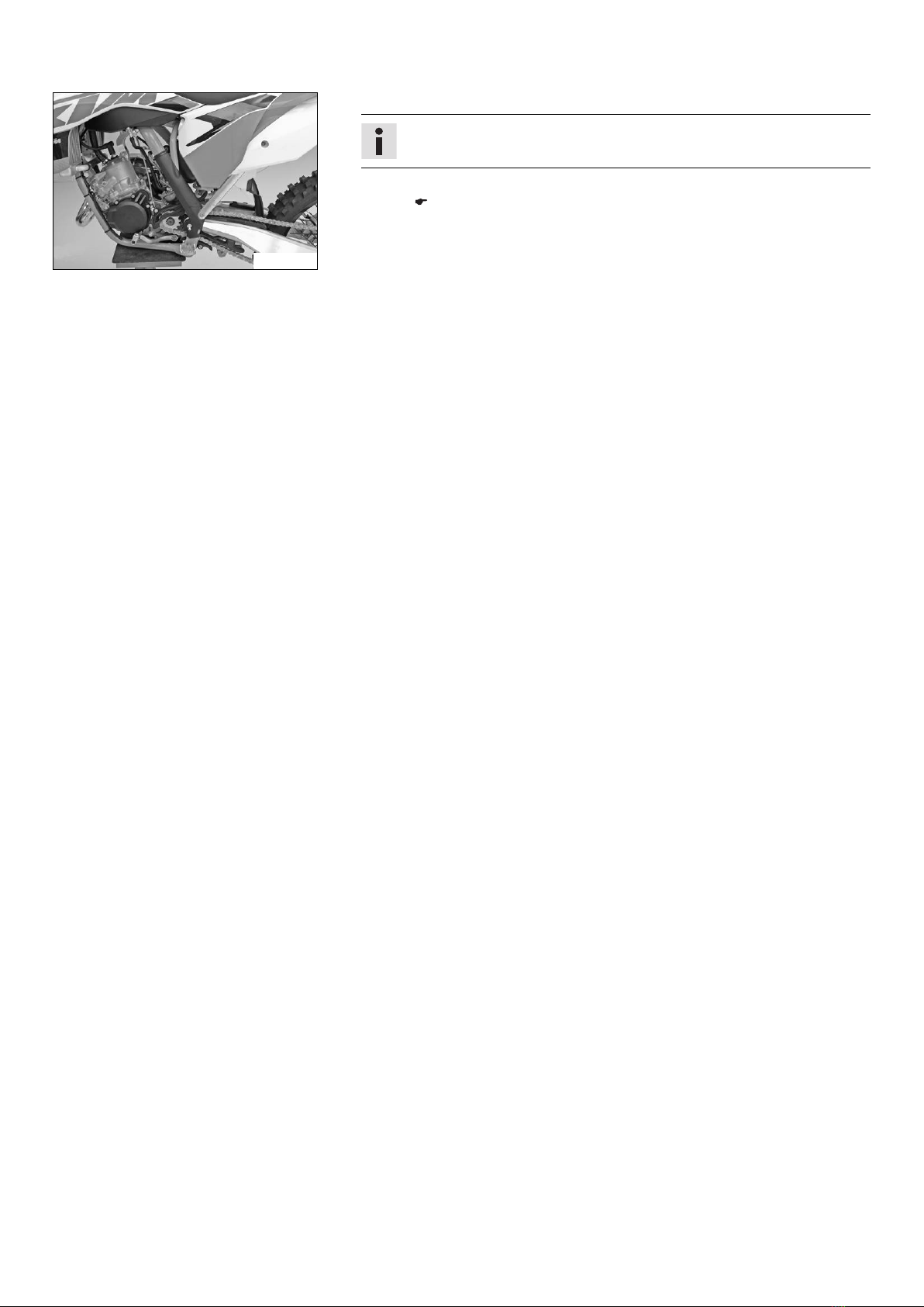
–Route the clutch line with the clutch master cylinder toward the front between
the upper and lower triple clamps.
(125/150 SX EU)
–Route the clutch line with the clutch master cylinder toward the front
between the upper and lower triple clamps.
S00867-14
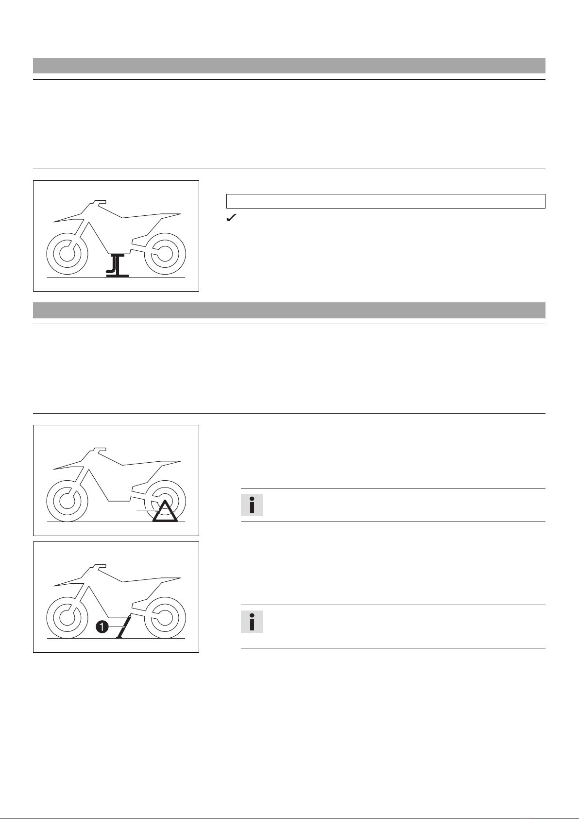
–Position the fork legs.
Bleeder screw of the right fork leg is positioned to the front.
Left fork leg valve is offset by approx. 20° to the front.
Info
Grooves are milled into the side of the upper end of the fork legs.
The second milled groove (from the top) must be flush with the top
edge of the upper triple clamp.
The air suspension is located in the left fork leg. The pressure and
rebound damping is located in the right fork leg.
–Tighten the screws of the triple clamp.
Guideline
Screw, top triple clamp M8 17 Nm
(12.5 lbf ft)
Screw, bottom triple clamp M8 12 Nm
(8.9 lbf ft)
M01401-10
(125/150 SX US, All 250/300 models)
–Position the fork legs.
Bleeder screws are positioned toward the front.
Info
The rebound damping is located in the right fork leg (red adjust-
ing screw). The compression damping is located in the left fork leg
(white adjusting screw).
Grooves are milled into the side of the upper end of the fork legs.
The second milled groove (from the top) must be flush with the top
edge of the upper triple clamp.
–Tighten the screws of the triple clamp.
Guideline
Screw, top triple clamp M8 17 Nm
(12.5 lbf ft)
Screw, bottom triple clamp M8 12 Nm
(8.9 lbf ft)
M01402-10
–Remove screws . Take off the handlebar clamps.
–Remove screws . Remove the handlebar support.
–Position rubber bushings and push through nuts from below.
–Place the handlebar support in the required position. Mount and tighten
screws .
Guideline
Screw, handlebar support M10 40 Nm
(29.5 lbf ft)
Loctite®243™


 Supplementary service manual")