3 WORK 8
Info
Even when there is no load on the battery, it still loses power steadily.
The charging level and the method of charging are very important for the service life of the battery.
Rapid recharging with a high charging current shortens the battery's service life.
If the charging current, charging voltage and charging time are exceeded, electrolyte escapes through the safety valves. This
reduces the battery capacity.
If the battery is depleted from starting the vehicle repeatedly, the battery must be charged immediately.
If the battery is left in a discharged state for an extended period, it will become over-discharged and sulfate, destroying the
battery.
The battery is maintenance-free, which means that the acid level does not need to be checked.
Preparatory work
–Switch off the ignition by turning the ignition key to position OFF .
–Remove the seat. ( p. 6)
–Remove the battery. ( p. 6)
S01013-10
Main work
–Connect the battery charger to the battery. Switch on the battery charger.
Battery charger (58429074000)
You can also use the battery charger to test rest potential and start potential of the
battery, and to test the alternator. With this device, you cannot overcharge the bat-
tery.
Info
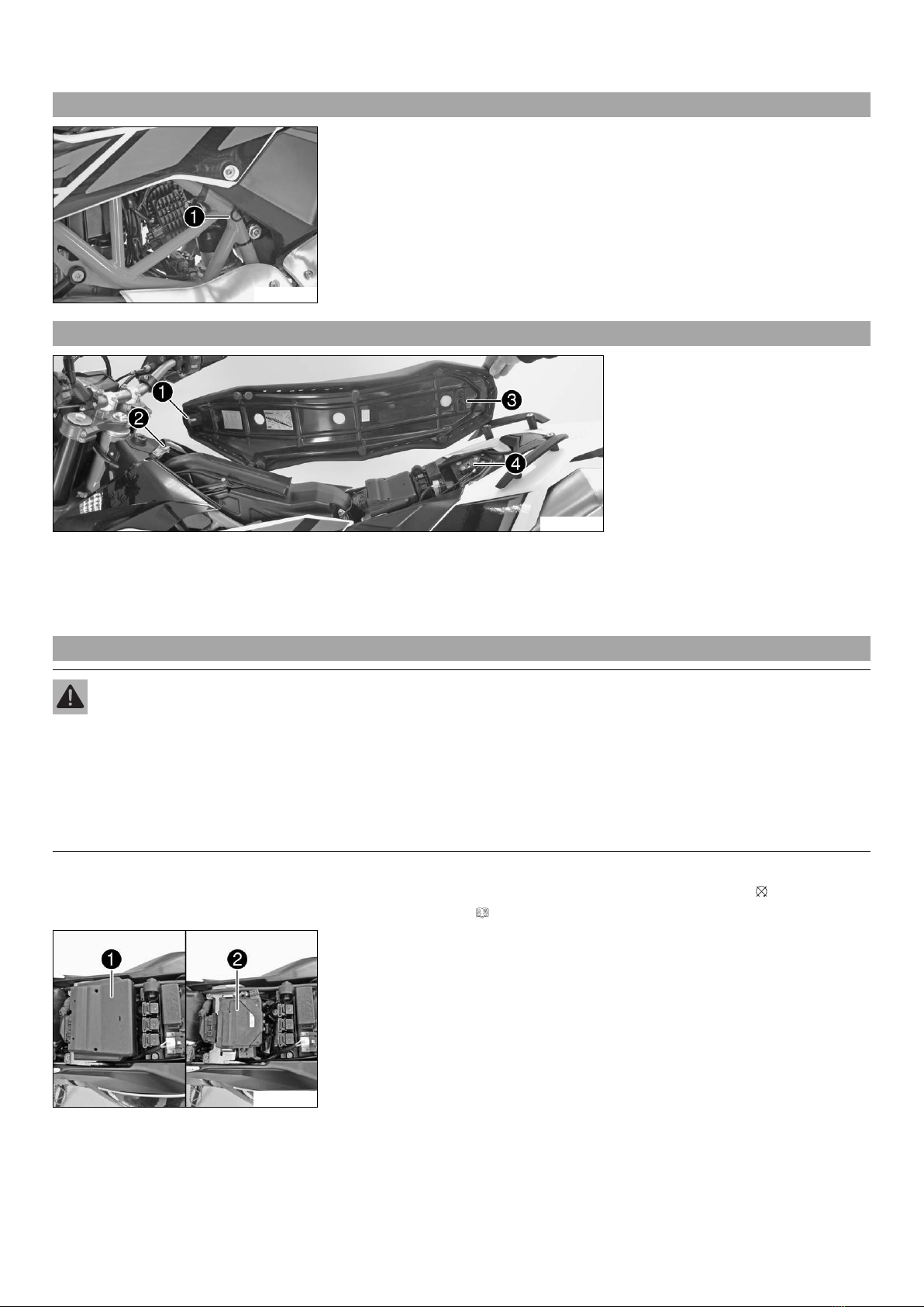
Never remove lid 1.
Charge the battery with a maximum of 10% of the capacity specified on the
battery housing 2.
–Switch off the battery charger after charging and disconnect from the battery.
Guideline
The charge current, charge voltage and charge time must not be exceeded.
Charge the battery regularly when the
motorcycle is not in use
3 months
Finishing work
–Install the battery. ( p. 8)
–Mount the seat. ( p. 6)
–Set the clock. ( p. 12)
3.5 Installing the battery
S00621-11
Main work
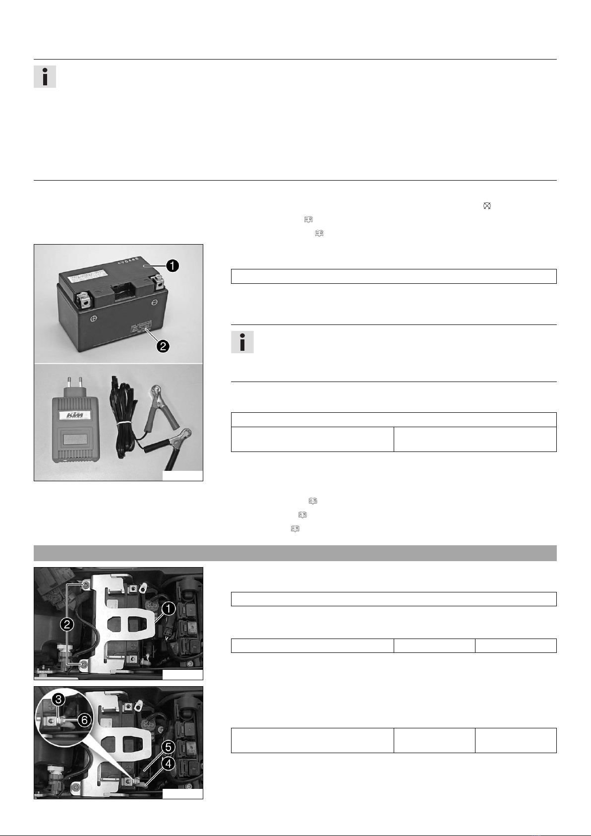
–Insert the battery into the battery compartment with the terminals facing rearward.
Battery (YTZ10S)
–Position retaining bracket 1and mount and tighten screws 2.
Guideline
Remaining screws, chassis M6 10 Nm (7.4 lbf ft)
S00623-10
–Position washer 3, positive cable 4, and ABS connection cable 5.
–Mount and tighten screw 6.
Guideline
Screw, battery terminal M6 4.5 Nm
(3.32 lbf ft)


 Supplementary service manual")