KTM 950 SUPERMOTO R User manual

950 SUPERMOTO
KTM Sportmotorcycle AG
A–5230 Mattighofen
www.ktm.at
11/2005 FOTO: MITTERBAUER
KTM Group Partner
ART. NR. 3.211.82EN
OWNER’S MANUAL 2006

We strongly suggest that you read this manual carefully and completely before going on your first ride. It contains a great deal of information and advice which will
help you use and handle your bike properly. In your own interest, please pay particular attention to notices that are marked as follows:
1
– IGNORING THESE INSTRUCTIONS, CAN ENDANGER YOUR
BODY AND YOUR LIFE.
– IGNORING THESE INSTRUCTIONS COULD CAUSE DAM-
AGE TO PARTS OF YOUR MOTORCYCLE OR THAT THE
MOTOR-CYCLE IS NOT ROAD-SAFE ANYMORE.
All information contained is without obligation. KTM-Sportmotorcycle AG particularly reserves the right to modify any equipment, technical specifications, prices,
colors, shapes, materials, services, service work, constructions, equipment and the like so as to adapt them to local conditions or to cancel any of the above items,
all without previous announcement and without giving reasons. KTM may stop manufacturing certain models without previous notice. KTM shall not be held liable
for any deviations of availability and/or ability to deliver, illustrations, descriptions, printing and/or other errors. The illustrated models partly contain extra equip-
ment, which is not applied to standard models.
© 2005 by KTM-SPORTMOTORCYCLE AG, Mattighofen AUSTRIA; All rights reserved; Reprint, also in extracts, with written allowance of KTM-SPORTMOTORCYCLE AG,
Mattighofen only.
COMSUMER INFORMATION FOR AUSTRALIA ONLY Tampering with noise control system prohibited Owners are warned that the law may prohibit:
(a) The removal or rendering inoperative by any person other than for purposes of maintenance, repair or replacement, of any device or element of design incorpo-
rated into any new vehicle for the purpose of noise control prior to its sale or delivery to the ultimate purchaser or while it is in use; and
(b) the use of the vehicle after such device or element of design has been removed or rendered inoperative by any person.
Frame number
Engine number
Key number
Stamp of dealer
Please insert the serial numbers of your motorcycle in the boxes below
IMPORTANT »

INTRODUCTION »2
We would like to congratulate you on your purchase of a KTM motorcycle.
You are now the owner of a state-of-the-art sport motorcycle that guarantees to bring you lots of fun and enjoyment, provided that
you clean and maintain it appropriately. Before you go for your first ride, be sure to read this manual carefully and thoroughly in
order to familiarize yourself with how to operate your new motorcycle and with its characteristics, even if this means that you will
have to dedicate some of your valuable time to this task. Only by doing so will you learn how to tune your motorcycle to your spe-
cific needs and how to protect yourself against injury. Besides, this manual contains important information on motorcycle mainte-
nance. At the time this manual was typeset, it was up-to-date with the latest state of this production series. It cannot be completely
ruled out, however, that minor discrepancies may exist resulting from further design upgrades of these motorcycles.This manual is
an important part of your motorcycle and should be passed on to any subsequent owner in case you decide to sell it.
We expressly point out that work marked with an asterisk in the chapter "Maintenance work on the chassis and engine" must be
performed. If maintenance work should become necessary during a competition it should be performed by a trained mechanic. KTM
strongly recommends that all service work to your KTM should be performed by a qualified KTM dealer.
For your own safety, use KTM-approved parts and accessories only. KTM is not liable for damage that arises in connection with the
use of other products.
Take special care to follow the recommended run in, inspection, and maintenance intervals. Heeding these guidelines will signifi-
cantly increase the life of your motorcycle. To ensure that all work to your KTM is performed properly and to avoid warranty con-
flicts, KTM recommends that you always have your KTM serviced by a recognized and qualified KTM dealer.
Motorcycle driving is a wonderful sport and we hope that you will be able to enjoy it to the full. It may, however, involve potential
problems for the environment or lead to conflicts with others. These problems or conflicts can be avoided if the motorcycle is used
responsibly. To safeguard the future of motorcycle sports, make sure that you use the motorcycle in accordance with the law, show
that you are environmentally conscious and respect the rights of others.
We wish you a lot of fun when driving !
KTM-SPORTMOTORCYCLE AG
5230 MATTIGHOFEN, AUSTRIA

IMPORTANT LIMITED WARRANTY AND LIMITED GUARANTEE INFORMATION »
In accordance with the international quality management ISO 9001 standard, KTM uses
quality assurance processes that lead to the highest possible product quality.
The 950 Supermoto is designed and constructed for normal use on public roads but not for use on race courses or offroad terrain.
The service, care and operating instructions for the engine and chassis specified in the owner's manual must be observed to ensure
that the bike runs smoothly and to avoid premature wear.
The service work described in the "Lubrication and maintenance chart" must be carried out by an authorized KTM workshop and
confirmed in the service manual, otherwise your warranty will become void.
The fuels and lubricants specified in the owner's manual or those of an equal quality must be used in accordance with the main-
tenance schedule.
The warranty or guarantee shall become void for damage and consequential damage caused by manipulations or conversions to the
motorcycle.
The use of the motorcycle under extreme conditions, e.g. on the race course, can cause above average wear to components such
as the brakes. In this case it may become necessary to service or replace wear parts before the service limit specified in the main-
tenance schedule has been reached.
3

INDEX »4
IMPORTANT . . . . . . . . . . . . . . . . . . . . . . . . . . . . . . . . . . . . .1
INTRODUCTION . . . . . . . . . . . . . . . . . . . . . . . . . . . . . . . . . .2
IMPORTANT LIMITED WARRANTY AND LIMITED
GUARANTEE INFORMATION . . . . . . . . . . . . . . . . . . . . . . . . .3
SERIAL NUMBER LOCATIONS . . . . . . . . . . . . . . . . . . . . . . . .6
Chassis number, Type label . . . . . . . . . . . . . . . . . . . . . . . . .6
Engine number, engine type . . . . . . . . . . . . . . . . . . . . . . . .6
OPERATION INSTRUMENTS . . . . . . . . . . . . . . . . . . . . . . . . .7
Clutch lever . . . . . . . . . . . . . . . . . . . . . . . . . . . . . . . . . . .7
Choke lever . . . . . . . . . . . . . . . . . . . . . . . . . . . . . . . . . . . .7
Hand brake lever . . . . . . . . . . . . . . . . . . . . . . . . . . . . . . . .7
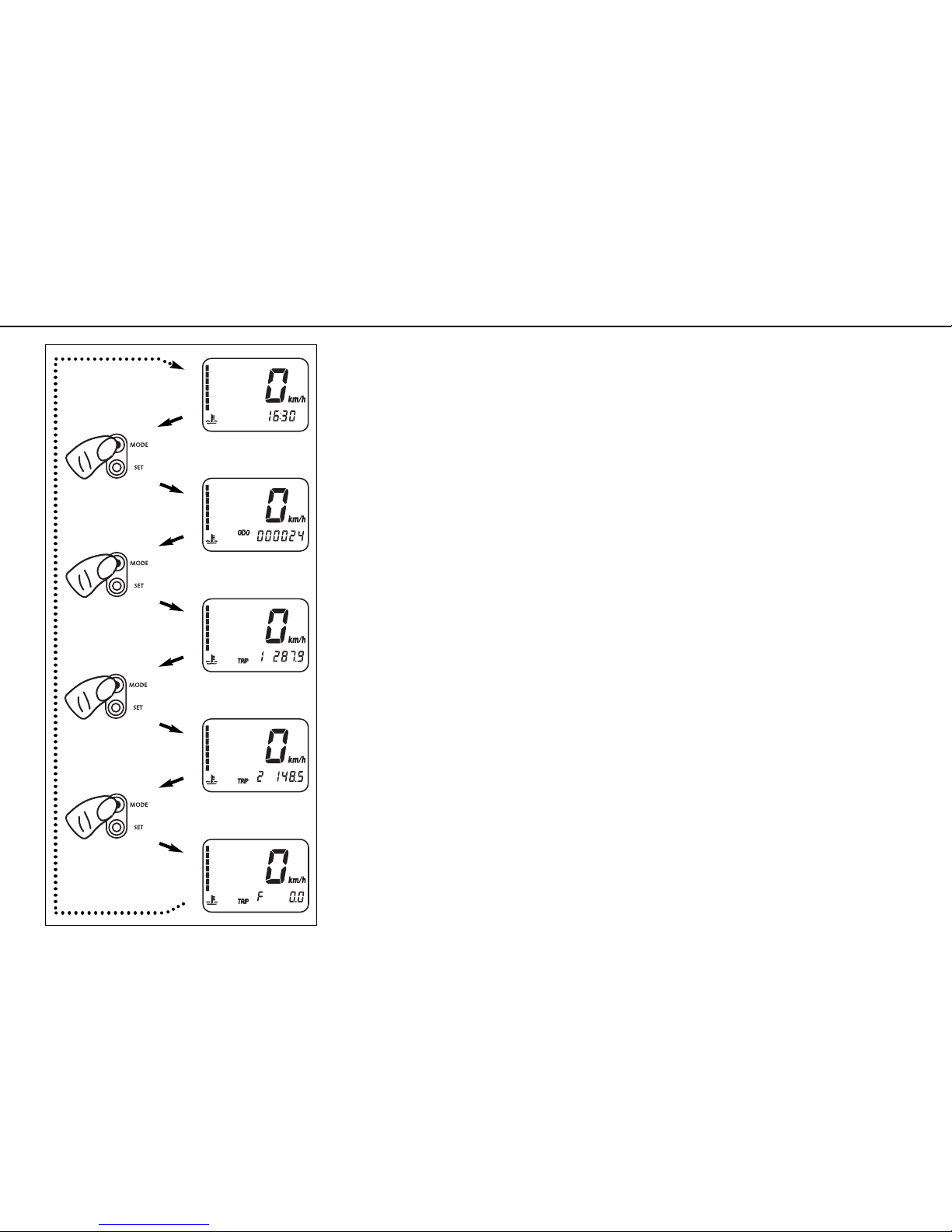
Multi-functional digital speedometer . . . . . . . . . . . . . . . . . .8
Display . . . . . . . . . . . . . . . . . . . . . . . . . . . . . . . . . . . . . . .8
Setting options in the display . . . . . . . . . . . . . . . . . . . . . .10
Cooling liquid temperature display . . . . . . . . . . . . . . . . . .12
Indicator lamps . . . . . . . . . . . . . . . . . . . . . . . . . . . . . . . .12
Ignition lock . . . . . . . . . . . . . . . . . . . . . . . . . . . . . . . . . .13
Combination switch . . . . . . . . . . . . . . . . . . . . . . . . . . . . .13
Emergency OFF tip switch, starter tip switch . . . . . . . . . . .14
Filler cap . . . . . . . . . . . . . . . . . . . . . . . . . . . . . . . . . . . .14
Fuel taps . . . . . . . . . . . . . . . . . . . . . . . . . . . . . . . . . . . .14
Baggage carrier, grips . . . . . . . . . . . . . . . . . . . . . . . . . . . .15
Seat lock, removing the seat . . . . . . . . . . . . . . . . . . . . . . .15
Tool set . . . . . . . . . . . . . . . . . . . . . . . . . . . . . . . . . . . . .16
Helmet lock . . . . . . . . . . . . . . . . . . . . . . . . . . . . . . . . . .16
Shift lever . . . . . . . . . . . . . . . . . . . . . . . . . . . . . . . . . . . .16
Side stand . . . . . . . . . . . . . . . . . . . . . . . . . . . . . . . . . . .17
Foot brake pedal . . . . . . . . . . . . . . . . . . . . . . . . . . . . . . .17
Footrests . . . . . . . . . . . . . . . . . . . . . . . . . . . . . . . . . . . .17
Compression damping of fork . . . . . . . . . . . . . . . . . . . . . .18
Rebound damping of fork . . . . . . . . . . . . . . . . . . . . . . . . .18
Spring preload of the fork . . . . . . . . . . . . . . . . . . . . . . . . .18
Damping action during compression of shock absorber . . . .19
Rebound damping of shock absorber . . . . . . . . . . . . . . . . .19
GENERAL TIPS AND WARNINGS FOR STARTING
THE MOTORCYCLE . . . . . . . . . . . . . . . . . . . . . . . . . . . . . . .20
Instructions for initial operation . . . . . . . . . . . . . . . . . . . .20
Running in the LC8 engine . . . . . . . . . . . . . . . . . . . . . . . .20
Accessories and payload . . . . . . . . . . . . . . . . . . . . . . . . . .21
DRIVING INSTRUCTIONS . . . . . . . . . . . . . . . . . . . . . . . . . .22
Check the following before each start . . . . . . . . . . . . . . . .22
Starting when the engine is cold . . . . . . . . . . . . . . . . . . . .24
Starting when the engine is warm or hot . . . . . . . . . . . . . .25
Starting off . . . . . . . . . . . . . . . . . . . . . . . . . . . . . . . . . . .25
Shifting/Riding . . . . . . . . . . . . . . . . . . . . . . . . . . . . . . . .25
Braking . . . . . . . . . . . . . . . . . . . . . . . . . . . . . . . . . . . . .26
Stopping and parking . . . . . . . . . . . . . . . . . . . . . . . . . . . .27
Fuel, refueling . . . . . . . . . . . . . . . . . . . . . . . . . . . . . . . . .28
PERIODIC MAINTENANCE SCHEDULE . . . . . . . . . . . . . . . . .29
MAINTENANCE WORK ON CHASSIS AND ENGINE . . . . . . . .33
Adjusting the fork and shock absorber . . . . . . . . . . . . . . .34
Adjusting compression damping of fork . . . . . . . . . . . . . . .34
Adjusting rebound damping of fork . . . . . . . . . . . . . . . . . .35
Adjusting the spring preload on the fork . . . . . . . . . . . . . . .35
Compression damping of shock absorber . . . . . . . . . . . . . .36
Rebound damping of shock absorber . . . . . . . . . . . . . . . . .37
Breathing the fork legs . . . . . . . . . . . . . . . . . . . . . . . . . .37
Checking the chain tension . . . . . . . . . . . . . . . . . . . . . . .38
Correcting the chain tension . . . . . . . . . . . . . . . . . . . . . .38
Chain maintenance . . . . . . . . . . . . . . . . . . . . . . . . . . . . .39

INDEX »5
Checking the chain for wear . . . . . . . . . . . . . . . . . . . . . . .39
General information on KTM disk brakes . . . . . . . . . . . . . .40
Changing the basic position of the handbrake lever . . . . . . .42
Checking the front brake fluid level . . . . . . . . . . . . . . . . .42
Refilling front brake fluid . . . . . . . . . . . . . . . . . . . . . . . . .42
Checking the front brake pads . . . . . . . . . . . . . . . . . . . . .43
Changing the basic position of the foot brake lever . . . . . . .44
Checking rear brake fluid level . . . . . . . . . . . . . . . . . . . . .44
Refilling the rear brake fluid reservoir . . . . . . . . . . . . . . . .44
Checking the rear brake pads . . . . . . . . . . . . . . . . . . . . . .45
Dismounting and remounting the front wheel . . . . . . . . . .46
Dismounting and mounting the rear wheel . . . . . . . . . . . . .48
Tires, air pressure . . . . . . . . . . . . . . . . . . . . . . . . . . . . . .50
Battery . . . . . . . . . . . . . . . . . . . . . . . . . . . . . . . . . . . . . .51
Charging the battery . . . . . . . . . . . . . . . . . . . . . . . . . . . .52
Jump start . . . . . . . . . . . . . . . . . . . . . . . . . . . . . . . . . . .52
Main fuse . . . . . . . . . . . . . . . . . . . . . . . . . . . . . . . . . . . .53
Fuses for individual power consumers . . . . . . . . . . . . . . . .54
Replacing the headlight lamp . . . . . . . . . . . . . . . . . . . . .55
Adjusting the headlight range . . . . . . . . . . . . . . . . . . . . . .56
Replacing the flasher bulbs . . . . . . . . . . . . . . . . . . . . . . .56
Replacing the brake light and taillight bulbs . . . . . . . . . . .57
Cooling system . . . . . . . . . . . . . . . . . . . . . . . . . . . . . . . .58
Checking the cooling liquid level in the compensating tank .59
Checking the cooling liquid level in the radiator . . . . . . . . .60
Bleeding the cooling system . . . . . . . . . . . . . . . . . . . . . . .60
Changing the original position of the clutch lever . . . . . . . .62
Checking the oil level of the hydraulic clutch . . . . . . . . . . .62
Checking and adjusting the throttle cable play . . . . . . . . . .63
Checking and adjusting the choke cable play . . . . . . . . . . .63
Adjusting the engine idle speed . . . . . . . . . . . . . . . . . . . .63
Engine oil . . . . . . . . . . . . . . . . . . . . . . . . . . . . . . . . . . . .64
Checking the engine oil level . . . . . . . . . . . . . . . . . . . . . .64
Refilling engine oil . . . . . . . . . . . . . . . . . . . . . . . . . . . . .65
Changing the engine oil and the oil filter, cleaning the oil
screen . . . . . . . . . . . . . . . . . . . . . . . . . . . . . . . . . . . . . .65
TROUBLESHOOTING . . . . . . . . . . . . . . . . . . . . . . . . . . . . . .68
CLEANING . . . . . . . . . . . . . . . . . . . . . . . . . . . . . . . . . . . . .72
CONSERVATION FOR WINTER OPERATION . . . . . . . . . . . . . .73
STORAGE . . . . . . . . . . . . . . . . . . . . . . . . . . . . . . . . . . . . . .74
TECHNICAL SPECIFICATIONS – CHASSIS . . . . . . . . . . . . . . .75
TECHNICAL SPECIFICATIONS – ENGINE . . . . . . . . . . . . . . .79
HEAD WORD INDEX . . . . . . . . . . . . . . . . . . . . . . . . . . . . . .81
CONSUMER INFORMATION FOR USA ONLY . . . . . . . . . . . . .83

Chassis number, Type label
The chassis number is stamped on the right side of the steering head tube. Enter this num-
ber in the field on page no 1.
The type label is located next to the chassis number.
Engine number, engine type
The engine number and the engine type are stamped into the left side of the engine below
the engine sprocket. Enter this number on page 1.
SERIAL NUMBER LOCATIONS »6

Clutch lever
The clutch lever [1] is fitted on the left hand side of the handle bar. The adjusting screw [A]
is used to change the original position of the clutch lever (see maintenance work on
chassis and engine).
The clutch is hydraulically actuated and adjusts itself automatically.
Choke lever
If the choke lever [2] is pulled backwards, a bore in the carburetors will be opened in the
carburetor through which the engine may draw in additional fuel. This produces a „rich“
fuel/air mixture necessary for cold start. The fuel quantity and thus the engine speed are
determined by the choke lever position.
At temperatures over 5°C (41°F) it will suffice to pull the choke lever half way out. At tem-
peratures below 5°C (41°F) the choke lever should be pulled all the way out. The hole is
closed again by pushing the choke lever all the way back in.
Hand brake lever
The hand brake lever [3] is mounted on the right side of the handlebar.The basic position
of the handbrake lever can be changed in 5 steps (see Maintenance work on chassis and
engine).
OPERATION INSTRUMENTS »7
3
2
A
1

Multi-functional digital speedometer
The universal instrument is divided into 3 parts.
Use the MODE and SET [1] button to change the display and the basic settings in the dis-
play.
Display [2] shows all of the information that may be of interest to you. 5 display modes can
be selected with the MODE button.
The indicator lamps [3] provide additional information on the motorcycle's running
condition.
Display
TEST
When you switch on the ignition, all of the display elements will light up for 1 second for
the function test.
WS (wheel size)
The display will change and show the diameter of the front wheel in inches for 1 second
(WS = wheel size).
Then the CLOCK mode will be displayed, or the mode that was active when the ignition was
switched off.
OPERATION INSTRUMENTS »8
TEST
WS
31 2

CLOCK
You will recognize the CLOCK display by the blinking dots between the hours and minutes.
It displays the speed, temperature of the cooling liquid and the clock.
To switch to the next display mode, press the MODE button.
ODO
The speed, temperature of the cooling liquid and the total kilometers or miles traveled are
shown in the ODO mode.
To switch to the next display mode, press the MODE button.
TRIP 1
The TRIP 1 mode shows the speed, the temperature of the cooling liquid and the trip
odometer 1.
To switch to the next display mode, press the MODE button.
TRIP 2
The TRIP 2 mode shows the speed, the temperature of the cooling liquid and the trip
odometer 2.
To switch to the next display mode, press the MODE button.
TRIP F
The TRIP F mode (fuel) displays the speed, the temperature of the cooling liquid and the
distance traveled since reaching the low-fuel mark (the low-fuel indicator lamp lights up).
To return to the CLOCK mode, press the MODE button.
OPERATION INSTRUMENTS »9
ODO
CLOCK
TRIP 1
TRIP 2
TRIP F

Setting options in the display
KILOMETERS OR MILES.
You can have the speed and distance shown in kilometers or miles in the display. The dis-
play can be adapted to the respective country on long-distance trips.
To switch from kilometers to miles, switch on the ignition and press the MODE [1] button
for approx. 10 seconds. The km/h display will switch to mph. The speed and the stored dis-
tances will be converted and displayed in miles.
To return to kilometers, proceed as described above.
SET CLOCK
Switch on the ignition and change to the CLOCK mode.
Simultaneously press MODE [1] and SET [2]. The numbers on the clock will start to blink.
Use the MODE button to set the hours and the SET button to set the minutes.
The press the MODE and SET buttons simultaneously.
NOTE:
0:00 will be displayed if the clock is not supplied with electricity. This can be caused by a
defective fuse or a fault in the board electric system (see Troubleshooting).
TRIP 1
The trip meter 1 runs continuously and counts up to 999.9. It can be used to measure the
length of a certain route on a trip or the distance between two refueling stops.
To return the trip meter 1 to zero, switch on the ignition, change to the TRIP 1 mode and
press the SET button [2].
OPERATION INSTRUMENTS »10
10 sec
2
2
1
1

RESETTING TRIP 2
The trip meter 2 runs continuously and counts up to 999.9. It can be used similarly to TRIP
1 or together with a switch available as an accessory (see below) for trips according to a
roadbook.
To return the trip meter 2 to zero, switch on the ignition, change to the TRIP 2 mode and
press the SET button [2].
TRIP F
When the fuel level reaches the reserve mark, the display will automatically switch to TRIP
F and begin to count (no matter which display mode was active before). At the same time,
the fuel warning lamp will light up. You will still have enough reserve fuel for at least
30 kilometers.
After refueling, it will take approx. 8 minutes for the fuel warning lamp to switch off and for
TRIP F to automatically reset to 0 and return to the previous display mode.
NOTE:
Press the SET key for 2 seconds to immediately turn off the fuel warning lamp.
OPERATION INSTRUMENTS »11
2

Cooling liquid temperature display
The temperature display [1] is shown in 7 bars. The more bars that light up, the hotter the
cooling liquid. When the lowest bar lights up, the cooling liquid has reached a temperature
of approx. 40°C (104°F). When the upper bar lights up 120°C (248°F), all of the bars will
start to blink and the red warning lamp [2] will light up.
POSSIBLE CAUSES FOR AN INCREASE IN TEMPERATURE, CAUSING THE RED WARNING LIGHT
FOR THE COOLING LIQUID TEMPERATURE TO LIGHT UP:
– DRIVING TOO SLOWLY AND DRIVING WITH A HEAVY LOAD AT HIGH AIR TEMPERATURES
– NOT ENOUGH COOLING LIQUID IN THE SYSTEM
– THE VENTILATOR ON THE LEFT RADIATOR IS NOT RUNNING
– IMPROPER USE OF THE CLUTCH WHEN DRIVING SLOWLY
Indicator lamps
The green indicator lamp will blink in the blinker rhythm when the blinker is switched on.
NOTE:
The indicator lamp will blink slower when a blinker is broken.
The green indicator lamp will light up when the gearbox is in an idling position.
The blue indicator lamp will light up when the high beams are switched on.
The red warning light will light up when the cooling liquid has reached a tempera-
ture of approx. 120°C (248°F).
The orange warning light will light up when the fuel level reaches the reserve mark.
At the same time the display will automatically change to TRIP F (see TRIP F).
The red warning lamp lights up when the ignition is switched on but the engine is
not running. When the engine is started, the warning lamp will go out as soon as the
oil pressure is high enough.
This indicator lamp has no function.
OPERATION INSTRUMENTS »12
120°C (248°F)
110°C (230°F)
100°C (212°F)
70°C (158°F)
60°C (140°F)
50°C (122°F)
40°C (104°F)
2
1

Ignition lock
The ignition lock has 3 switching positions.
Ignition off, (engine can't be started)
Ignition on, light on, (engine can be started)
Ignition off, handlebar blocked
To switch the ignition to position turn the ignition key to position and firmly press it
into the lock. Turn the handlebar to the left, then turn the ignition key to the left.
The ignition key can be withdrawn in position and .
Combination switch
The rocker switch LIGHTS [1] actuates the high beam or low beam.
High-beam light
Low-beam light
The light signal (high beam) is actuated with button [2].
The indicator switch [3] returns to central position after actuation. Press flasher switch
towards switch housing to switch off the flasher.
The horn is sounded with button [4].
OPERATION INSTRUMENTS »13
4
3
1
1
2

Emergency OFF tip switch, starter tip switch
The emergency off switch [1] is provided for emergency situations and should not be used
to switch off the engine.
The engine is ready for operation in position (ignition circuit and starter circuit are switched
on).
The engine cannot be started in position (ignition circuit and starter circuit are inter-
rupted).
Use the starter tip switch [2] to operate the electric starter.
Filler cap
The filler cap [3] can be locked and is provided with a fuel evaporation control system.
To open the cap insert the ignition key, turn it 90° counterclockwise, then lift off the filler
cap.
To close the tank insert the filler cap, turn the ignition key 90° clockwise and take out the
key.
OPERATION INSTRUMENTS »14
Fuel taps
2 fuel taps [4] are mounted on the fuel tank that must be open when the motorcycle is run-
ning. The level in the fuel tanks is equalized by means of a connecting hose.
The fuel pump stops running when the engine is switched off and fuel cannot flow to the
carburetors so the fuel taps do not need to be closed when the motorcycle is switched off.
Opening the fuel tap: Turn the knob all the way to the left.
Closing the fuel tap: Turn the knob all the way to the right.
44
3
1
2

Seat lock, removing the seat
The seat lock [3] can be locked with the ignition key.
To remove the seat, insert the ignition key and turn 45° in a counterclockwise direction. Lift
the seat in the back, pull back and lift off.
Baggage carrier, grips
The baggage carrier [1] can carry a load of up to 8 kg.
The passenger can hold on to the grips [2] during the ride.
To mount the seat, attach the seat to the oval head screw [4], lower the seat in the back
while sliding it towards the front. Both noses [5] should fit into the frame. Insert the catch
bolts [6] in the lock housing and push the seat down in the back until you hear the catch
bolts snap into place.
Check whether the seat is correctly mounted.
IF NOT CORRECTLY MOUNTED, THE SEAT CAN SLIP WHILE YOU ARE DRIVING AND CAUSE YOU
TO LOSE CONTROL OF YOUR MOTORCYCLE.
OPERATION INSTRUMENTS »15
1
2
3
4
5
6

Tool set
The tool set [1] is located in the storage compartment under the seat.
Helmet lock
The steel rope [2] in the tool bag can be used to secure a helmet.
To secure, remove the seat, run the rope through the helmet, attach both ends to the hook
[3] and mount the seat.
THE HELMET LOCK IS PROVIDED TO SECURE THE HELMET TO THE MOTORCYCLE WHEN PARKED.
DO NOT ATTACH THE HELMET OR OTHER OBJECTS TO THE STEEL ROPE WHILE DRIVING. YOU
CAN EASILY LOSE CONTROL OF THE MOTORCYCLE.
Shift lever
The shift lever is mounted on the left side of the engine. The position of the gears is shown
in the illustration. Neutral, or the idle speed, is located between first and second gear.
OPERATION INSTRUMENTS »16
1
2,3,4,5,6
N
2
3
1

Side stand
Fold the side stand [1] forward to the stop with your foot and put the weight of the motor-
cycle on the stand. Make sure it is standing securely on a firm surface. The side stand is
linked to the safety start system; follow the driving instructions.
Foot brake pedal
The foot brake pedal [2] is located in front of the right footrest. Its basic position can be
adjusted to your seat position (see maintenance work).
Footrests
The passenger footrests [3] fold up.
OPERATION INSTRUMENTS »17
3
2
1

Compression damping of fork
The fork's damping action during compression travel (compression damping) can be adjusted.
This allows you adjust the damping behavior to match your driving style and the payload.
The adjusting screws [1] are located on the fork leg axle passage.
More information is provided in the chapter "Adjusting the fork and shock absorber.“
Rebound damping of fork
The fork's damping action during rebound travel (rebound damping) can also be adjusted.
This allows you adjust the damping behavior to match your driving style and the payload.
The adjusting screws [2] are located on the upper end of the fork legs.
More information is provided in the chapter "Adjusting the fork and shock absorber.“
Spring preload of the fork
The fork's preload can be adjusted by means of the adjusting screws [3].
More information is provided in the chapter "Adjusting the fork and shock absorber.“
OPERATION INSTRUMENTS »18
3
2
1

Damping action during compression of shock absorber
The shock absorber's damping action during compression travel (compression damping) can
be adjusted. This allows you adjust the shock absorber's damping behavior to match your
driving style and the payload.
The damping rate can be adjusted in the low and high-speed range (Dual Compression Control).
The designation low and high-speed refers to the movement of the shock absorber and not
to the motorcycle's driving speed.
The adjusting screw [1] for the low-speed range can be adjusted with a screwdriver.
The adjusting screw [2] for the high-speed range can be adjusted with a 17 mm socket wrench.
More information is provided in the chapter "Adjusting the fork and shock absorber.“
Rebound damping of shock absorber
The shock absorber's damping action during rebound travel (rebound damping) can also be
adjusted. This allows you adjust the damping behavior to match your driving style and the
payload.
The adjusting screw [3] is located on the bottom of the shock absorber.
More information is provided in the chapter "Adjusting the fork and shock absorber.“
OPERATION INSTRUMENTS »19
12
3
Other manuals for 950 SUPERMOTO R
1
Table of contents
Other KTM Motorcycle manuals

KTM
KTM 950 ADVENTURE 2003 User manual

KTM
KTM 85 SX 2021 Manual

KTM
KTM LC4 ADVENTURE R 640 2000 User guide

KTM
KTM 640 LC4 Adventure User manual

KTM
KTM 350 EXC-F SIX DAYS EU User manual

KTM
KTM 625 SXC User manual

KTM
KTM 1190 RC8 R EU/UK 2009 User manual

KTM
KTM 390 Duke 2016 User manual

KTM
KTM RC 125 EU 2015 User manual

KTM
KTM 990 SUPERMOTO 2008 User manual