KTM 350 EXC-F AUS 2012 Manual

SETUP INSTRUCTIONS 2012
350 EXC‑F EU
350 EXC‑F AUS
350 EXC‑F SIX DAYS EU
350 EXC‑F USA
350 XCF‑W USA
Art. no. 3211775en


INTRODUCTION 1
INTRODUCTION
The work described in these setup instructions must be performed before the vehicle is delivered to the customer.
Read the setup instructions in their entirety before beginning work.
Print out the current PDI form found on the KTM DEALER.NET.
These setup instructions were written to correspond to the latest state of this series. We reserve the right to make changes in the inter-
est of technical advancement without at the same time updating this manual.
We shall not provide a description of general workshop methods. Likewise, safety rules that apply in a workshop are not specified here.
It is assumed that the work will be performed by a fully trained mechanic.
All specifications are non-binding. KTM Sportmotorcycle AG specifically reserves the right to modify or delete technical specifica-
tions, prices, colors, forms, materials, services, designs, equipment, etc., without prior notice and without specifying reasons, to adapt
these to local conditions, as well as to stop production of a particular model without prior notice. KTM accepts no liability for delivery
options, deviations from illustrations and descriptions, as well as misprints and other errors. The models portrayed partly contain spe-
cial equipment that does not belong to the regular scope of delivery.
© 2011 KTM-Sportmotorcycle AG, Mattighofen Austria
All rights reserved
Reproduction, even in part, as well as copying of all kinds, is permitted only with the express written permission of the copyright
owner.
ISO 9001(12 100 6061)
According to the international quality management standard ISO 9001, KTM uses quality assurance processes that lead
to the maximum possible quality of the products.
Issued by: TÜV Management Service
KTM-Sportmotorcycle AG
5230 Mattighofen, Austria

MEANS OF REPRESENTATION 2
Symbols used
The meaning of specific symbols is described below.
Indicates an expected reaction (e.g. of a work step or a function).
Indicates an unexpected reaction (e.g. of a work step or a function).
Indicates a page reference (more information is provided on the specified page).
Indicates information with more details or tips.
Indicates the result of a testing step.
Denotes a voltage measurement.
Denotes a current measurement.
Denotes a resistance measurement.
Formats used
The typographical formats used in this document are explained below.
Proprietary name Identifies a proprietary name.
Name®Identifies a protected name.
Brand™ Identifies a trademark.

SETUP 3
2.1Unpacking and setting up the vehicle
C00103-01
Packaging 2
–Remove the box and the plastic packaging.
Info
To avoid damaging the motorcycle during the setup, leave the protective
film on the vehicle until you have finished.
–Remove the separate enclosure and unpack it. Check that the scope of delivery
is complete on the basis of the enclosed packing list.
–Have a lift stand available.
Lift stand (54829055000)
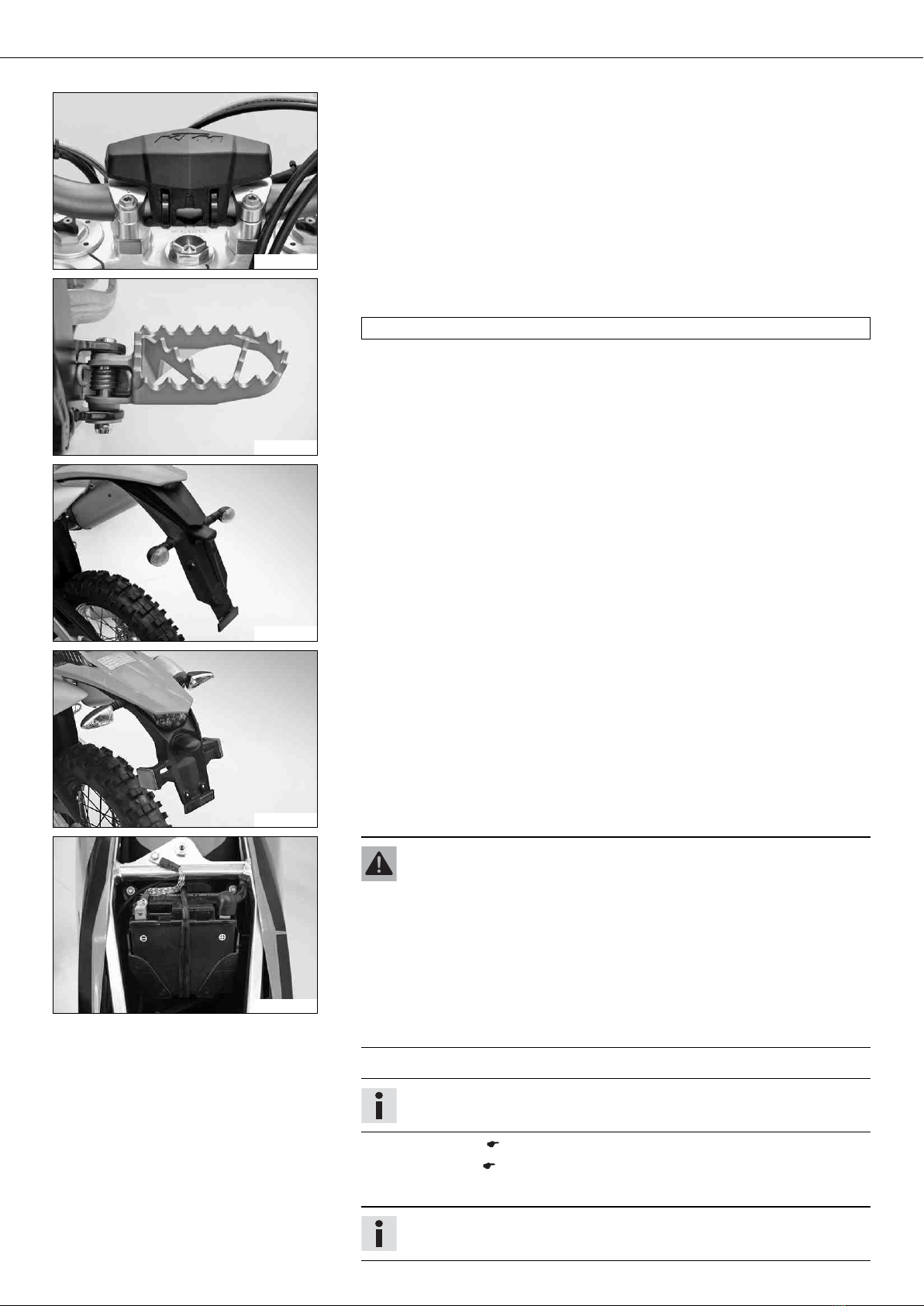
–Carefully loosen and remove the footrest mount.
Info
An assistant prevents the motorcycle from falling over.
601706-01
–Together with an assistant, take the vehicle off the palette.
–Position the vehicle on a lift stand.
–Check the vehicle for transport damage.
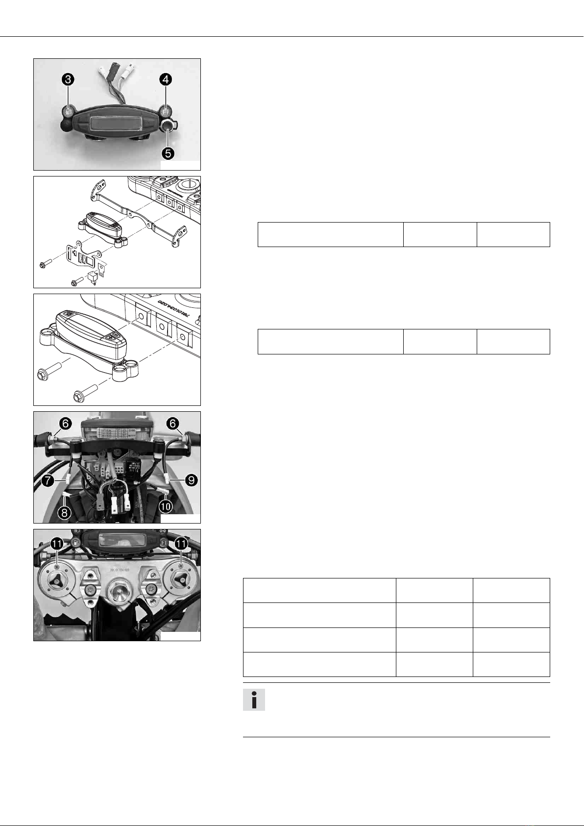
–Remove the headlight mask with the headlight. ( p. 8)
C00104-01
Package 12
–Remove the box and the plastic packaging.
Info
An assistant prevents the motorcycle from falling over.
To avoid damaging the motorcycle during the setup, leave the protective
film on the vehicle until you have finished.
–Remove the separate enclosure and unpack it. Check that the scope of delivery
is complete on the basis of the enclosed packing list.
C00105-01
–Have a lift stand available.
Lift stand (54829055000)
–Together with an assistant, take the vehicle off the palette.
–Position the vehicle on a lift stand.
–Check the vehicle for transport damage.
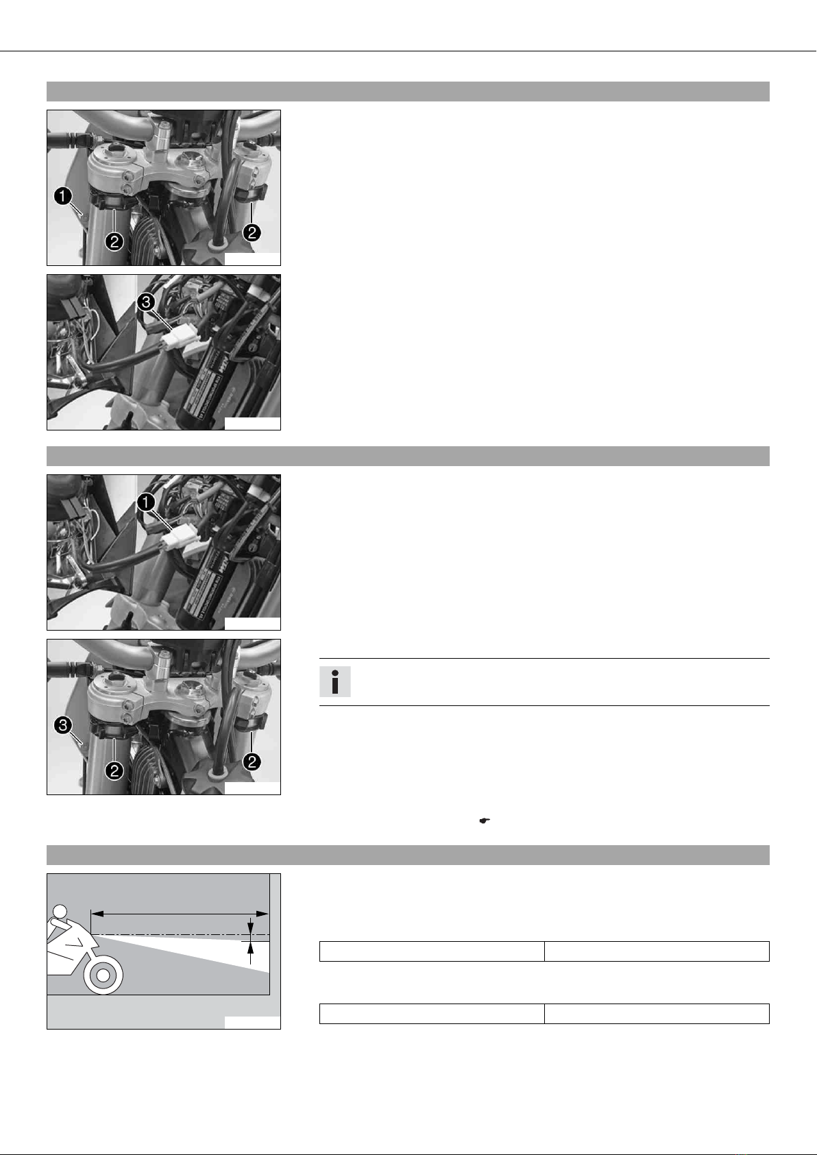
–Install the shock absorber. ( p. 9)
601704-10
(All EXC‑F models)
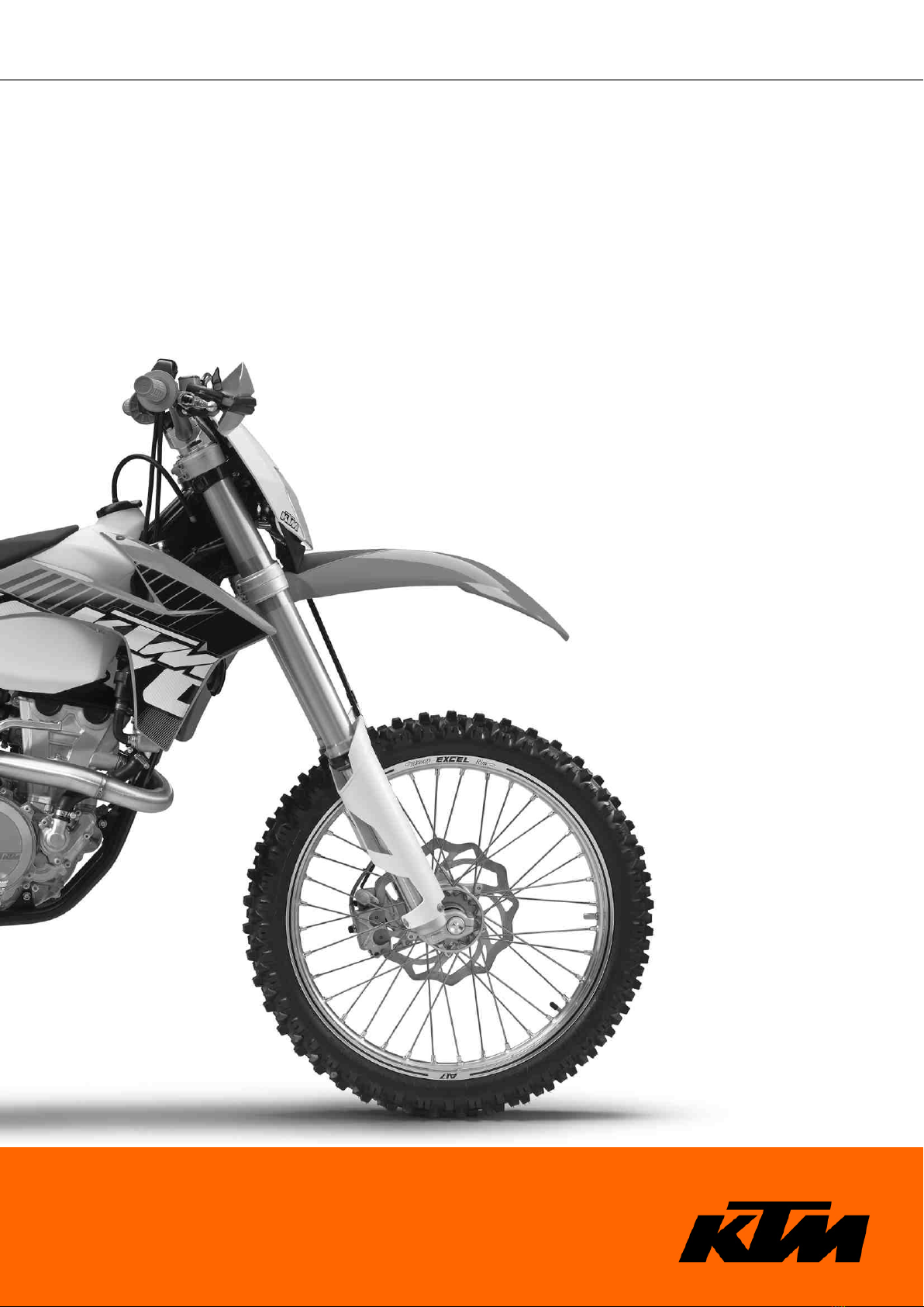
–Insert the indicator lamp with the blue and brown cable colors into
socket 1.
–Insert the indicator lamp with the blue and violet cable colors into
socket 2.
–Insert the indicator lamp with the brown/red and yellow/blue cable colors
into socket 3.
–Insert indicator lamp LED with the white and orange cable colors into
socket 4.

SETUP 4
C00115-10
(XCF‑W)
–Insert the indicator lamp with the brown/red and yellow/blue cable colors
into socket 3.
–Insert indicator lamp LED with the white and orange cable colors into
socket 4.
–Connect pull switch 5with the yellow and white cables.
401380-01
(All EXC‑F models)
–Attach the retaining bracket for the connector, the turn signal bracket with
the turn signal, and the speedometer to the upper triple clamp.
Guideline
Remaining screws, chassis M6 10 Nm
(7.4 lbf ft)
401381-01
(XCF‑W)
–Attach the speedometer to the upper triple clamp.
Guideline
Remaining screws, chassis M6 10 Nm
(7.4 lbf ft)
601705-10
(All EXC‑F models)
–Mount and tighten nuts 6of the turn signals on both sides.
–Connect connector 7of the right turn signal with connector 8, which is
marked green.
–Connect connector 9of the left turn signal with connector bk, which is
marked red.
601707-10
–Route the clutch line with the clutch master cylinder toward the front between
the upper and lower triple clamps.
–Position the fork legs and tighten the screws of the triple clamp.
Guideline
Screw, top triple clamp
(EXC‑F EU/AUS/USA, XCF‑W)
M8 20 Nm
(14.8 lbf ft)
Screw, bottom triple clamp
(EXC‑F EU/AUS/USA, XCF‑W)
M8 15 Nm
(11.1 lbf ft)
Screw, top triple clamp (EXC-F SIX
DAYS)
M8 17 Nm
(12.5 lbf ft)
Screw, bottom triple clamp (EXC-F
SIX DAYS)
M8 12 Nm
(8.9 lbf ft)
Info
The topmost milled groove in the fork leg must be flush with the top
edge of the upper triple clamp.
Position bleeder screws bl toward the front.

SETUP 5
C00108-10
–Position the handlebar.
Info
Make sure cables and wiring are positioned correctly.
–Position the handlebar clamps. Mount and tighten the screws.
Guideline
Screw, handlebar clamp M8 20 Nm
(14.8 lbf ft)
Info
The markings on the handlebar should be at the center of the handlebar
clamps.
Keep the gap widths equal when tightening.
C00110-10
–Position the controls on the right half of the handlebar.
Info
The routing of the cables and throttle cables can be seen in the figure.
401382-01
(All EXC‑F models)
–Mount the turn signal switch.
C00111-10
–Position the controls on the left half of the handlebar.
Info
The figure shows how to route the clutch line and wiring harness.
–Install the front fender. ( p. 10)
–Refit the headlight mask with the headlight. ( p. 8)
–Install the front wheel. ( p. 9)
–Correctly mount the fuel tank breather.

SETUP 6
601710-01
–Secure the handlebar cushion with two cable binders.
101019-01
–Mount the footrests with the springs and bolts. Secure the bolts using the washers
and pins.
Pliers for footrest spring (58429083000)
601711-01
(EXC‑F EU, EXC‑F AUS, EXC-F SIX DAYS)
–Mount the license plate holder with the license plate lamp, turn signals, and
reflector.
–Connect the electrical components.
–Connect the connector of the left turn signal with connector that is marked red.
–Connect the connector of the right turn signal with connector that is marked
green.
C00117-01
(350 EXC‑F USA)
–Mount the license plate holder with the license plate lamp, turn signals, and
reflector.
–Connect the electrical components.
–Connect the connector of the left turn signal with connector that is marked red.
–Connect the connector of the right turn signal with connector that is marked
green.
800035-10
Warning
Risk of injury Battery acid and battery gases cause serious chemical burns.
–Keep batteries out of the reach of children.
–Wear suitable protective clothing and goggles.
–Avoid contact with battery acid and battery gases.
–Keep the battery away from sparks or open flames. Charge only in well-
ventilated areas.
–In the event of skin contact, rinse with large amounts of water. If battery
acid gets in the eyes, rinse with water for at least 15 minutes and con-
tact a physician.
–Fill the battery.
Info
Read the notes in the battery package.
–Charge the battery. ( p. 11)
–Install the battery. ( p. 10)
–Unpack and mount the KTM PowerParts included in the delivery (optional).
Info
Read the accompanying KTM PowerParts installation instructions.

WORK 8
3.1Removing headlight mask with headlight
101401-10
–Switch off all electrical equipment.
–Remove screw 1and take off clamp.
–Loosen the rubber band 2. Push up the headlight mask and swing it forwards.
C00124-11
–Pull out the electric plug connector 3and remove the headlight mask with the
headlight.
3.2Refitting the headlight mask with the headlight
C00124-10
Main work
–Connect the electric plug connector 1.
101401-11
–Position the headlight mask and fix it with the rubber band 2.
Info
Ensure that the retaining lugs engage in the fender.
–Position the brake line and wiring harness. Put the clamp on, mount and tighten
screw 3.
Subsequent work
–Check the headlight setting. ( p. 8)
3.3Checking the headlight setting
0
0
AA
0
0
BB
400726-10
–Position the vehicle upright on a horizontal surface in front of a light wall and make
a mark at the height of the center of the low beam headlight.
–Make another mark a distance Bunder the first mark.
Guideline
Distance B5 cm (2 in)
–Position the vehicle vertically a distance Aaway from the wall.
Guideline
Distance A5 m (16 ft)
–The rider now sits down on the motorcycle.
–Switch on the low beam.

WORK 9
–Check the headlight setting.
The boundary between light and dark must be exactly on the lower mark for a
motorcycle with driver.
» If the light-dark border does not meet specifications:
–Adjust the headlight range.
3.4Installing the shock absorber
101344-11
Main work
–Push splash protector 1to the side and position the shock absorber. Mount and
tighten screw 2.
Guideline
Screw, top shock absorber M12 80 Nm
(59 lbf ft)
Loctite®2701
–Mount and tighten screw 3.
Guideline
Screw, bottom shock
absorber
M12 80 Nm
(59 lbf ft)
Loctite®2701
Info
The heim joint for the shock absorber at the swing arm is Teflon coated. It
must not be greased with grease or with other lubricants. Lubricants dis-
solve the Teflon coating, thereby drastically reducing the service life.
Subsequent work
–Remove the motorcycle from the lift stand.
3.5Installing the front wheel
Warning
Danger of accidents Reduced braking efficiency due to oil or grease on the brake discs.
–Always keep the brake discs free of oil and grease, and clean them with brake cleaner when necessary.
101388-11
–Check the wheel bearing for damage and wear.
» If the wheel bearing is damaged or worn:
–Change the wheel bearing.
–Clean and grease shaft seal rings 1and bearing surface Aof the spacers.
Long-life grease ( p. 16)
–Insert the spacers.
101386-11
–Lift the front wheel into the fork, position it, and insert the wheel spindle.
–Mount and tighten screw 2.
Guideline
Screw, front wheel spindle M24x1.5 45 Nm
(33.2 lbf ft)
–Activate the hand brake lever multiple times until the brake linings are in contact
with the brake disc.
–Remove the motorcycle from the lift stand.
–Pull the front wheel brake and push down hard on the fork several times to align
the fork legs.
–Fully tighten screw 3.
Guideline
Screw, fork stub M8 15 Nm
(11.1 lbf ft)

WORK 10
3.6Installing the front fender
101345-10
–Ensure that the spacers are mounted in the fender.
–Position the front fender. Mount and tighten screws 1.
Guideline
Remaining screws, chassis M6 10 Nm (7.4 lbf ft)
Info
Make sure the holding lugs engage in the start number plate or headlight
mask.
3.7Removing the seat
101346-10
–Remove screw 1.
–Lift up the seat at the rear, pull it back and then remove it from above.
3.8Mounting the seat
101347-01
–Hook in the front of the seat at the collar sleeve of the fuel tank, lower it at the rear
and simultaneously push it forward.
–Make sure that the seat is correctly locked in.
–Mount and tighten the screw of the seat fixing.
Guideline
Remaining screws, chassis M6 10 Nm (7.4 lbf ft)
3.9Installing the battery
101394-10
Main work
–Insert battery into the battery compartment with the terminals facing to the front.
Battery (YTX4L-BS)
–Reconnect rubber band 1.
–Connect positive cable 2and negative cable 3.
Guideline
Screw, battery terminal M5 2.5 Nm
(1.84 lbf ft)
Info
Contact disks Amust be mounted between battery terminals 4and cable
sockets 5with the claws facing up.
–Slide positive terminal cover 6over the positive terminal.
Subsequent work
–Mount the seat. ( p. 10)

WORK 11
3.10Charging the battery
Warning
Risk of injury Battery acid and battery gases cause serious chemical burns.
–Keep batteries out of the reach of children.
–Wear suitable protective clothing and goggles.
–Avoid contact with battery acid and battery gases.
–Keep the battery away from sparks or open flames. Charge only in well-ventilated areas.
–In the event of skin contact, rinse with large amounts of water. If battery acid gets in the eyes, rinse with water for at least
15 minutes and contact a physician.
Warning
Environmental hazard The battery contains elements that are harmful to the environment.
–Do not discard batteries with the household trash. Dispose of a defective battery in an environmentally compatible manner.
Give the battery to your KTM dealer or to a recycling center that accepts used batteries.
Warning
Environmental hazard Hazardous substances cause environmental damage.
–Oil, grease, filters, fuel, cleaners, brake fluid, etc., should be disposed of as stipulated in applicable regulations.
Info
Even when there is no load on the battery, it still loses power steadily.
The charge state and the type of charge are very important for the service life of the battery.
Rapid recharging with a high charging current shortens the battery's service life.
If the charging current, charging voltage and charging time are exceeded, electrolyte escapes through the safety valves. This
reduces the battery capacity.
If the battery is depleted from starting the vehicle repeatedly, the battery must be charged immediately.
If the battery is left in a discharged state for an extended period, it will become over-discharged and sulfate, destroying the
battery.
The battery is maintenance-free, which means that the acid level does not need to be checked.
Preliminary work
–Switch off all power consumers and switch off the engine.
–Remove the seat. ( p. 10)
–Disconnect the negative cable of the battery to avoid damage to the onboard elec-
tronics.
400240-10
Main work
–Connect the battery charger to the battery. Switch on the battery charger.
Battery charger (58429074000)
You can also use the battery charger to test the open-circuit voltage and starting
voltage of the battery, and to test the alternator. With this device, you cannot over-
charge the battery.
Info
Never remove lid 1.
Charge the battery with at most 10% of the capacity specified on the bat-
tery housing 2.
–Switch off the battery charger after charging. Disconnect the battery.
Guideline
The charge current, charge voltage, and charge time must not be exceeded.
Charge the battery regularly when the
motorcycle is not in use
3 months
Subsequent work
–Mount the seat. ( p. 10)

WORK 12
3.11Opening filler cap
Danger
Fire hazard Fuel is highly flammable.
–Never refuel the vehicle near open flames or burning cigarettes, and always switch off the engine first. Be careful that no
fuel is spilt, especially on hot vehicle components. Clean up spilt fuel immediately.
–Fuel in the fuel tank expands when warm and can escape if the tank is overfilled. See the notes on refueling.
Warning
Danger of poisoning Fuel is poisonous and a health hazard.
–Avoid contact between fuel and skin, eyes and clothing. Do not inhale fuel vapors. If fuel gets into your eyes, rinse immedi-
ately with water and contact a doctor. Wash affected skin areas immediately with soap and water. If fuel is swallowed, con-
tact a doctor immediately. Change clothing that has come into contact with fuel. Store fuel in a suitable canister according
to regulations and keep it out of the reach of children.
Warning
Environmental hazard Improper handling of fuel is a danger to the environment.
–Do not allow fuel to get into the ground water, the ground, or the sewage system.
101305-10
–Press release button 1, turn filler cap counterclockwise and lift it upwards and
remove.
3.12Closing filler cap
101306-10
–Replace the filler cap and turn clockwise until the release button 1locks in place.
Info
Route the fuel tank breather hose 2without kinking.
3.13Refueling
Danger
Fire hazard Fuel is highly flammable.
–Never refuel the vehicle near open flames or burning cigarettes, and always switch off the engine first. Be careful that no
fuel is spilt, especially on hot vehicle components. Clean up spilt fuel immediately.
–Fuel in the fuel tank expands when warm and can escape if the tank is overfilled. See the notes on refueling.
Warning
Danger of poisoning Fuel is poisonous and a health hazard.
–Avoid contact of the fuel with skin, eyes and clothing. Do not inhale fuel vapors. If fuel gets into your eyes, rinse imme-
diately with water and contact a doctor. Wash affected skin areas immediately with soap and water. If fuel is swallowed,
contact a doctor immediately. Change clothing that has come into contact with fuel.
Note
Material damage Premature clogging of the fuel filter.
–In some countries and regions, the available fuel quality and cleanliness may not be sufficient. This will result in problems with
the fuel system.

WORK 13
–Only refuel with clean fuel that meets the specified standards.
Warning
Environmental hazard Improper handling of fuel is a danger to the environment.
–Do not allow fuel to get into the ground water, the ground, or the sewage system.
–Switch off engine.
–Open the filler cap. ( p. 12)
AA
401226-10
–Fill the fuel tank with fuel up to measurement A.
Guideline
Measurement of A35 mm (1.38 in)
Total fuel tank
capacity,
approx. (XCF‑W,
350 EXC‑F USA)
8.5 l
(2.25 US gal)
Super unleaded (ROZ 95/RON 95/PON
91) ( p. 15)
Total fuel tank
capacity, approx.
(EXC‑F EU,
EXC‑F AUS,
EXC-F SIX DAYS)
9 l (2.4 US gal) Super unleaded (ROZ 95/RON 95/PON
91) ( p. 15)
–Close the filler cap. ( p. 12)

TECHNICAL DATA - TIGHTENING TORQUES FOR CHASSIS 14
Spoke nipple, front wheel M4.5 5… 6 Nm (3.7… 4.4 lbf ft) –
Screw, battery terminal M5 2.5 Nm (1.84 lbf ft) –
Screw, intake air temperature sensor M5 2 Nm (1.5 lbf ft) –
Screw, shock absorber adjusting ring M5 5 Nm (3.7 lbf ft) –
Screw, spoiler on fuel tank (XCF‑W,
350 EXC‑F USA)
M5x12 1.5 Nm (1.11 lbf ft) –
Spoke nipple, rear wheel M5 5… 6 Nm (3.7… 4.4 lbf ft) –
Remaining nuts, chassis M6 10 Nm (7.4 lbf ft) –
Remaining screws, chassis M6 10 Nm (7.4 lbf ft) –
Screw, ball joint of push rod on foot
brake cylinder
M6 10 Nm (7.4 lbf ft) Loctite®243™
Screw, chain sliding guard M6 6 Nm (4.4 lbf ft) Loctite®243™
Screw, front brake disc M6 14 Nm (10.3 lbf ft) Loctite®243™
Screw, rear brake disc M6 14 Nm (10.3 lbf ft) Loctite®243™
Fuel connection on fuel pump M8 10 Nm (7.4 lbf ft) –
Nut, foot brake lever stop M8 20 Nm (14.8 lbf ft) –
Nut, rear sprocket screw M8 35 Nm (25.8 lbf ft) Loctite®2701
Nut, rim lock M8 10 Nm (7.4 lbf ft) –
Remaining nuts, chassis M8 25 Nm (18.4 lbf ft) –
Remaining screws, chassis M8 25 Nm (18.4 lbf ft) –
Screw, bottom triple clamp (EXC-F SIX
DAYS)
M8 12 Nm (8.9 lbf ft) –
Screw, bottom triple clamp
(EXC‑F EU/AUS/USA, XCF‑W)
M8 15 Nm (11.1 lbf ft) –
Screw, chain sliding piece M8 15 Nm (11.1 lbf ft) –
Screw, engine brace M8 33 Nm (24.3 lbf ft) –
Screw, fork stub M8 15 Nm (11.1 lbf ft) –
Screw, front brake caliper M8 25 Nm (18.4 lbf ft) Loctite®243™
Screw, handlebar clamp M8 20 Nm (14.8 lbf ft) –
Screw, side stand attachment M8 45 Nm (33.2 lbf ft) Loctite®2701
Screw, subframe M8 35 Nm (25.8 lbf ft) Loctite®2701
Screw, top steering stem (EXC-F SIX
DAYS)
M8 17 Nm (12.5 lbf ft) Loctite®243™
Screw, top steering stem
(EXC‑F EU/AUS/USA, XCF‑W)
M8 20 Nm (14.8 lbf ft) –
Screw, top triple clamp (EXC-F SIX
DAYS)
M8 17 Nm (12.5 lbf ft) –
Screw, top triple clamp
(EXC‑F EU/AUS/USA, XCF‑W)
M8 20 Nm (14.8 lbf ft) –
Engine attachment bolt M10 60 Nm (44.3 lbf ft) –
Remaining nuts, chassis M10 45 Nm (33.2 lbf ft) –
Remaining screws, chassis M10 45 Nm (33.2 lbf ft) –
Screw, handlebar support M10 40 Nm (29.5 lbf ft) Loctite®243™
Nut, fuel pump fixation M12 15 Nm (11.1 lbf ft) –
Screw, bottom shock absorber M12 80 Nm (59 lbf ft) Loctite®2701
Screw, top shock absorber M12 80 Nm (59 lbf ft) Loctite®2701
Nut, seat fixing M12x1 20 Nm (14.8 lbf ft) –
Nut, swingarm pivot M16x1.5 100 Nm (73.8 lbf ft) –
Nut, rear wheel spindle M20x1.5 80 Nm (59 lbf ft) –
Screw, top steering head M20x1.5 12 Nm (8.9 lbf ft) –
Screw-in nozzles, cooling system M20x1.5 12 Nm (8.9 lbf ft) Loctite®243™
Screw, front wheel spindle M24x1.5 45 Nm (33.2 lbf ft) –

SUBSTANCES 15
Super unleaded (ROZ 95/RON 95/PON 91)
According to
–DIN EN 228 (ROZ 95/RON 95/PON 91)
Guideline
–Only use unleaded super fuel that matches or is equivalent to the specified fuel grade.
–Fuel with an ethanol content of up to 10 % (E10 fuel) is safe to use.
Info
Do not use fuel containing methanol (e. g. M15, M85, M100) or more than 10 % ethanol (e. g. E15, E25, E85, E100).

AUXILIARY SUBSTANCES 16
Long-life grease
Guideline
–KTM recommends Motorex®products.
Supplier
Motorex®
–Bike Grease 2000

*3211775en*
3211775en
KTM-Sportmotorcycle AG
5230 Mattighofen/Austria
http://www.ktm.com
09/2011
Photo: Mitterbauer
This manual suits for next models
4
Table of contents
Other KTM Motorcycle manuals

KTM
KTM 150 SX 2017 User manual

KTM
KTM 890 DUKE GP 2022 User manual

KTM
KTM 350 EXC-F EU 2013 User manual

KTM
KTM 50 SX 2019 User manual

KTM
KTM 250 SX-F EU 2012 User manual

KTM
KTM 990 SUPER DUKE User manual

KTM
KTM 250 EXC TPI User manual

KTM
KTM 1290 Super Duke GT User manual

KTM
KTM 890 DUKE R 2022 Manual

KTM
KTM 350 SX-F 2020 User manual