KTR Kupplungstechnik
GmbH
D-48407 Rheine
NVT-E
Operating-/Assembly Instructions
KTR-N
Sheet:
Edition:
42611 EN
8 of 27
1
Please note protection
mark ISO 16016.
Drawn: 11.10.12 Pz/Wy Replaced for: ---
Verified: 19.11.12 Pz Replaced by:
4 Operation
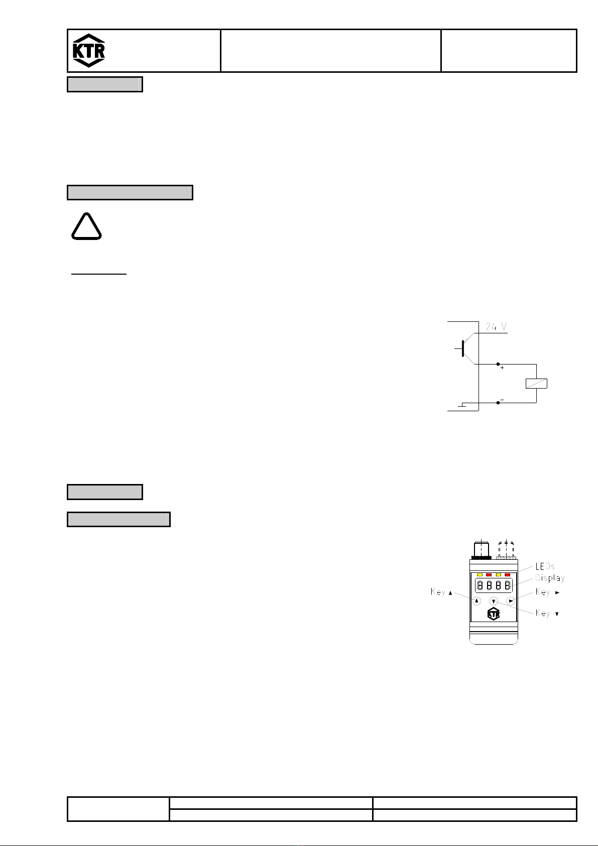
4.3 Key Functions
To select a menu item and set the values please proceed as follows:
Open the main menu via the key .
Select the submenu via the keys and and open the submenu via the key .
If applicable, select the next submenu via the keys and and open it using the key .
Select the requested menu item via the keys and and open the parameter list via the key .
Set the value using the keys and and accept via the key .
The amended settings are saved and the device returns to the submenu.
Exit the submenu by selecting menu item EXIT and press key to accept.
The device returns to the superordinate menu or measured value display, respectively.
4.4 Key Lock Active
If the key lock is activated, retrieving the menu via key shows the display
instead of the main menu. The active digit is indicated by a dot.
Enter the code via the keys and and press the key to accept.
The active digit shifts to the right by one place. Having entered the 3rd digit the main menu is opened.
ATTENTION!
Having entered an incorrect code, the device returns to measured value display. If you have
lost the password, enter the master code 287 to return to the menu.
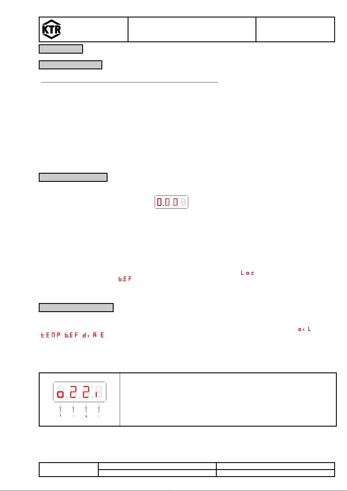
To unlock the key lock, reset the password to the input 000 in the menu item in the sub-menu Basic
Settings Extended Functions .
4.5 Summary of Menu
The menu structure is based on the VDMA standard 24574 and following.
The menu has a hierarchy structure. The highest menu level includes input of the main menu, e. g. ,
, , , . Each main menu comprises further submenu items.
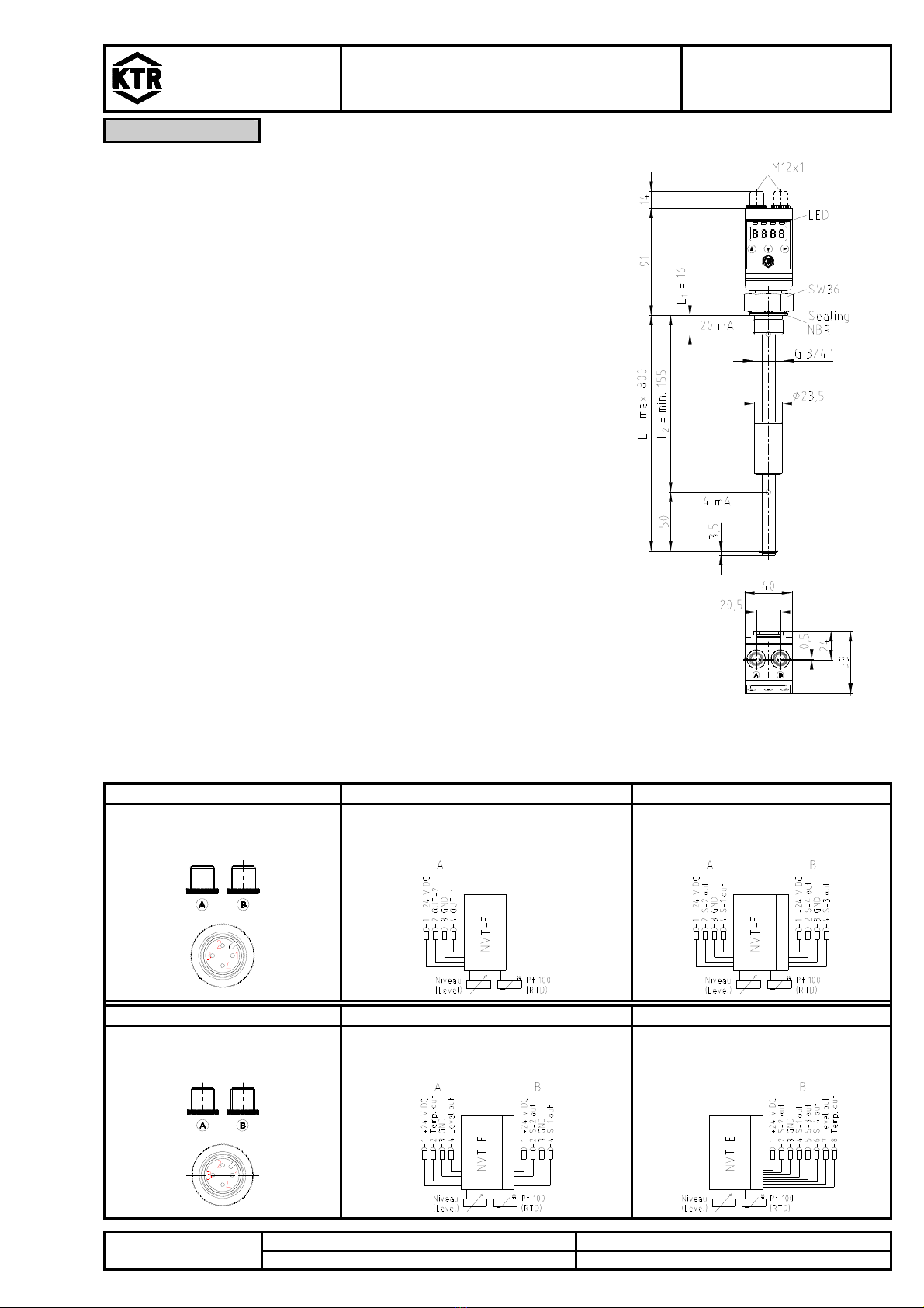
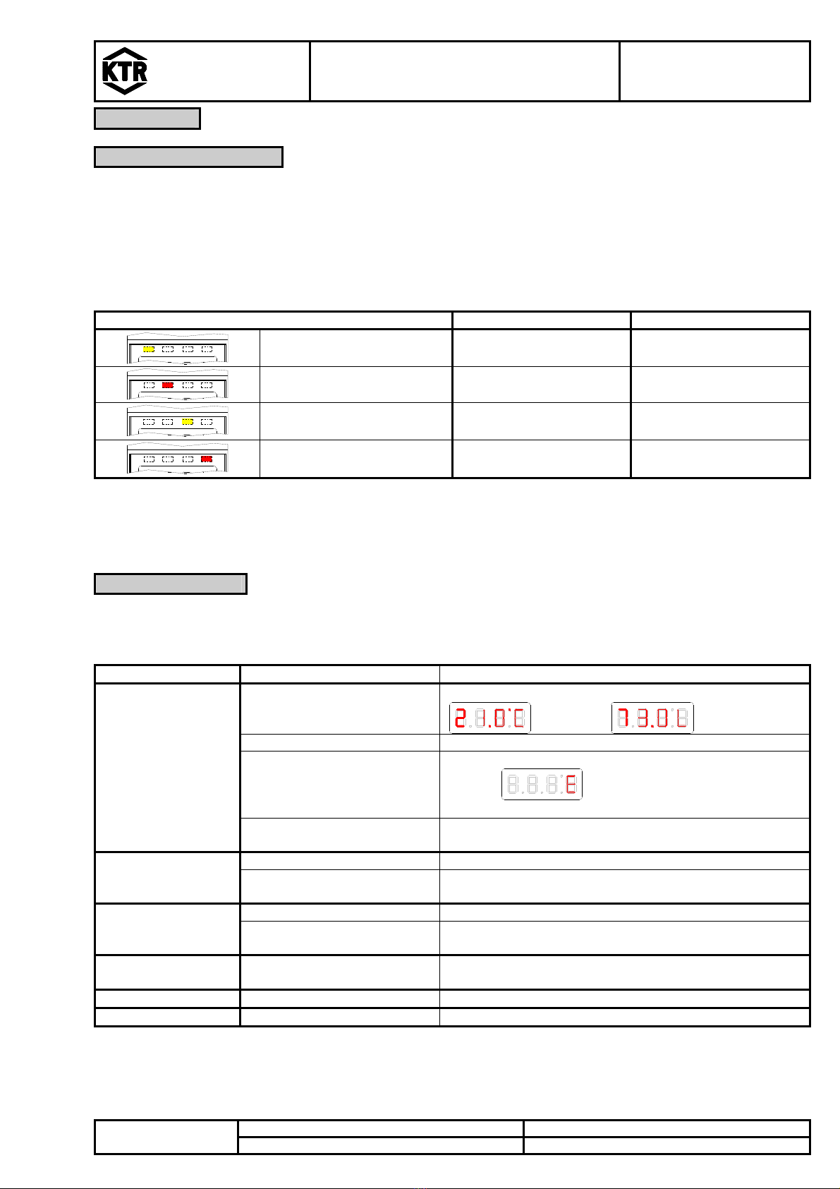
The menu items may vary depending on the configuration of the device. Your device may not provide all menu
items described below. You can retrieve the configuration by pressing the key in the display mode. A 4-digit
code is displayed, e. g.:
Meaning of the 4-digit code tsav:
t: Type
s: number of switching outputs
a: number of analogue outputs
v: mounting of device
t = temperature measurement
o = level and temperature measurement
2 or 4
0 or 2
i = standard mounting (installation of
tank)