KUDOS Original6 User manual

1Issue 01 MAR.19
Pozi-head Screwdriver Flat-head Screwdriver
3mm Allen Key - supplied Cutting Pliers
Junior Hacksaw Clear Silicone Sealant
7mm Masonry Drill Bit Drill (Battery or Mains)
Spirit Level Tape Measure
Marking Paste (Shoe Polish)
INSTALLATION INSTRUCTIONS - CURVED OFFSET SIDE ACCESS
Please read these instructions throughout before installing as incorrect tting will invalidate the guarantee.
If you are unsure about these instructions please contact Kudos Shower Products 01539 564040.
HEALTH & SAFETY WARNING
DUE TO THE WEIGHT & SIZE OF THE GLASS PANEL(s) A MINIMUM OF TWO PERSONS ARE REQUIRED
TO MOVE AND INSTALL THIS ENCLOSURE
For the wall post and xings use only warm soapy water and damp cloth/ sponge
on a regular basis. After cleaning please rinse with clean water to remove any
residue.
Do not use abrasive scouring powders, chemicals or aerosol cleaners - these may
result in damage to the surfaces, in particular, the plated component parts.
The glass panels are pre-treated with Life Shield on the inside surfaces only.
Whilst this makes cleaning the glass easier and helps prevent the build up of
harmful lime-scale and soap deposits, the glass still needs to be maintained on a
regular basis. We recommend the use of a detergent and aroma free glass cleaner
(A 50/50 mix of white vinegar and water works well).
DO NOT use strong detergents, abrasive cleaners or abrasive scrubbing
equipment for cleaning, these can damage the coating.
DO use a squeegee to remove remaining droplets of water from glass after
showering, any build up of residue can be removed easily using an appropriate
cleaner and agitation from soft cleaning equipment.
Cleaning - General
Kudos LifeShield Glass Treatment
Important
Check appearance of all product - any defects must be reported to Kudos Shower
Products before assembly/installation. Claims for imperfections will only be
accepted prior to assembly/installation.
Any claims made under the terms of the Lifetime Guarantee must be reported to
Kudos within 21 days of the fault occurring.
Check the enclosure adjustment sizes are suitable for your installation.
Use care when drilling into the walls to avoid hidden pipes or electric cables.
Stage 2
silicone sealant
Stage 1
Shower Tray
Ensure the top of shower tray is
LEVEL in ALL directions.
Once the tray is installed but
before the wall tiles are tted, any
gap between the tray and the walls
must be lled with silicone sealant
ush with the top of the tray.
Once the walls have been tiled but
before the enclosure is installed,
the tiles must be silicone sealed to
the tray all of the way around in
one continuous bead.
Failure to follow these
instructions will result in
leakage problems.
THESE INSTRUCTIONS ARE TO BE LEFT
WITH THE CONSUMER
Tools Required
original6original6

2Issue 01 MAR.19
Step 1 - Determine Opening Side
1. Stand the ‘Door Glass Assembly’ (CRV-S) upright,
leaning against a wall with the curved face (the
outside) coming away from the wall, ensuring all
contact corners are protected. Determine if the
shower enclosure is to be opening from the left or
right (the handle will be next to the wall when in the
closed position).
Parts List
Installation Pack
1 x CRV-F
Fixed Glass Panel
2 x M54-01
Height Adj. Base
2 x M54-02
Height Adj. Cam
2 x M56-01
Wall Jamb Top
Cap
2 x M56-02
Comp. Chnl. Top
Cap
6 x 6mm
Wall Plugs
12 x No.8x30 PH
S/S Screws
2 x No.4x10 CSK
S/S Screws
Installation Steps
1 x M97-01
Shim
2 x PlexF05
Glazing Wedge Seal
2. Once the ‘handing’ has been determined, t the
two ‘Top Roller Assemblies’ to the top corners of the
glass, with the wheels facing the outside. To do this,
the screw is removed using the 3mm Allen key, and
the small casting half and patch pad are placed to the
inside of the glass, before the wheel casting and patch
are placed to the outside of the glass, The screw is
reinserted and tightened.
1 x
Curved Rail Left
1 x CRV-S
Door Glass Assembly
8 x No.6x30 PH
S/S Screws
2 x M276-01
Patch Guide Caps
1 x M73-02
Top Cap Left
1 x M73-01
Top Cap Right
1873 & 1912mm
PlexRF023 Overlap Seals
1 x
Fixed Panel Wall Post
1 x
Door Panel Wall Post
2 x DCM-86-ASM
Top Roller Assembly
1 x DCM-89-R-ASM
Bottom Guide Right
1 x DCM-89-L-ASM
Bottom Guide Left
3. Now take the right and left ‘Bottom Guides’ and
t to the bottom left and right corners of the glass.
Again removing the screw, and sandwiching the
glass between the two casting and patches pads,
before reinserting the screw and tightening, ensuring
the grooved retaining arms are to the outside and
pointing to the centre.
Step 2 - Remove Angle Compensator Posts
1. Taking the two ‘Wall Post Assemblies,’ unclip and
remove the angled compensator post prole from
each post, retaining them for later steps.
Step 3 - Handing of Unit
1. This stage will determine which side you wish to t the xed panel glass, to the left or to the right of
the unit, to suit your installation. Arrange the wall posts into the correct position, either left or right
depending on the door opening and xed panel.
View From
Outside
Door opening for this example
THIS FACE TO OUTSIDE
1 x
Curved Rail Right
2 x No.6x12 PH
S/S Screws
2 x DCM-85-ASM
Glass Patch Clamp
Closing Side (for example) Fixed Side (for example)

3Issue 01 MAR.19
1. Insert ‘Height Adj. Cam (M54-02)’ into the hole
on bottom corner of the outer face of the frame,
ensure the cam is orientated as shown.
2. Slide the ‘Height Adj. Base (M54-01)’ into the
frame, over the ‘Height Adj. Cam,’ It ‘clicks’ once
engaged.
3. Push the ‘Height Adj. Base’ fully into the frame,
ush to the bottom. Repeat for opposite side.
Step 6 - Fit Height Adjusters
Step 5 - Remove Clip-In Extrusions
1. Locate the clip-in extrusions down the in side of the frame, press and
rotate the clip-in extrusion at top, middle and bottom of door frame, to
gently prise the extrusion away from the frame by hand only. (Handing
shown below for example only).
2. Remove the clip-in extrusion from each side of the frame.
3. Ensure the removed extrusions are kept separate, as left and right.
Step 8 - Adjust Height
1. Using a spirit level, check to
see if the bottom frame is level,
ensure the spirit level is sat down
fully onto the curved rail.
2. Using a at-head screwdriver adjust
the two nylon height adjustment screws
(lower screw in each post). Adjust until
the bottom frame is level.
Step 4 - Assemble Framework
1. Using the ‘No. 6’s x 30mm’ long screws and ‘Curved Rails,’ insert each screw
through the relevant holes in white plastic spacer blocks on the wall posts and into
each screw-port, two screws for each corner of frame, ensuring these are fully
tightened by hand. The side of the curved rails with the screwed in ‘stop’ should
be to the xed glass panel side, opposite to the door opening. Also ensure that the
curved rails are tted ush with ends of each wall-post.
Door Opening Side Fixed Panel Side
Step 7 - Ret the Angles
Step 9 - Position on Tray
1. Ret angle compensator
post to the wall-posts,
ensuring the curved faces are
to inside of unit.
1. Position frame onto the
tray, holding each wall-post,
carefully position unit centrally
onto tray. Once each wall
post is spaced equally away
from the edge of the tray,
mark the wall on the inside of
the compensator posts.
Step 10 - Mark Position of Holes
1. Remove the frame assembly away from the tray,
remove the two angle compensator posts from the
frame.
2. Place each post back onto the tray, with the
bottom edge of each post on the pencil marks made
in Step 9. Using a spirit level, check that each post
‘plumb’ vertical.
3. Using a 3mm rod (we recommend a small Allen
key or drill bit), place a small amount of marking paste
(we recommend shoe polish) on the end of the rod,
and ‘spot’ through the 3 screw slots down angled
compensator post.
Pencil Mark
from Step 9

4Issue 01 MAR.19
Step 11 - Check Planned Placement of Compensator Channels
1. Refer to diagrams below to ensure that the correct channel is tted to the correct side
‘Narrow’
Compensating channel
(shown actual size)
‘Narrow’
Compensating channel
(shown actual size)
‘1000’ SIDE ‘1000’ SIDE
‘810’ SIDE
‘810’ SIDE
‘Wide’
Compensating channel
(shown actual size)
‘Wide’
Compensating channel
(shown actual size)
2. For Step 20 identify left or right hand cover cap, as appropriate, to the top of ‘Wide’ compensating channel.
VIEW FROM TOP
LEFT HAND
INSTALLATION
VIEW FROM TOP
RIGHT HAND
INSTALLATION

5Issue 01 MAR.19
6 x No.8
Step 12 - Drill Mounting Holes & Insert Wall Plugs
1. Remove the posts from the tray,
placing safely off to one-side.
2. Using a 7mm masonry drill bit and
drill (or appropriate drill bit if drilling
tiles), drill six holes using the ‘spot’
marks from step 10, each hole should
be 30mm in depth.
3. Insert the six ‘6mm Wall Plugs’ into
the six holes.
Step 13 - Fitting the Frame
1. Insert the angle compensator posts
back into position on the tray. Using
a spirit level, check that the posts are
‘plumb’ vertical and the slotted holes in
the posts line up with the plugs in the
wall.
2. Using 6 x No.8 Pan-head 30mm screws provided, screw the posts to the wall on
each side. Be sure not to over tighten the middle screws (nger tighten only) as this
may cause “bowing” of the post. Rest a straight edge against the post edge on the
wall, you’ll be able to see any bowing that may have occurred. The middle screws
may now be adjusted to assist in plumbing the post and removing the “bow.”
Step 16 - Shim Frame
1. Often shower trays have different
angled top faces, in order to help
keep the frame supported use the
‘Shim (M97-01)’ supplied. On the
inside of the enclosure measure the
gap between the bottom of the rail
and top of the tray, select the height
required from the shim strip supplied,
break off and insert under rail at xed
panel clamp position (hole drilled
on curved rail). This will support rail
when glass is tted. The shim will be
concealed by silicone sealant later.
45mm Deep
30mm Deep
1. Ret the frame on to the tray,
ensuring the compensator channels
fully engage securely into the wall
posts down the entire length of each
side.
6 x No.8
2. Fix the frame to the compensator channels using six No.8 Pan-
head 30mm long panhead screws, through wall post mouldings into
pre-drilled holes in compensator channels (3 each side).
Do not over-tighten these screws.
Step 15 - Adjust Fit
1. Using a at headed screwdriver, adjust the six nylon adjustment screws,
three down each side, in an anti-clockwise direction, until the frame has
expanded and is only slightly wedged. Try to adjust each side equally, to
achieve equal spacings down each side of the frame and concentricity
between the bottom rail and tray.
=
Equal Wall
Spacing
Step 14 - Re-t Frame and Compensator Channels

6Issue 01 MAR.19
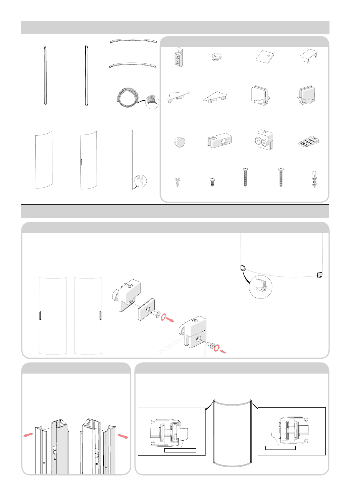
Step 19 - Fit Seal to Fixed Glass Panel
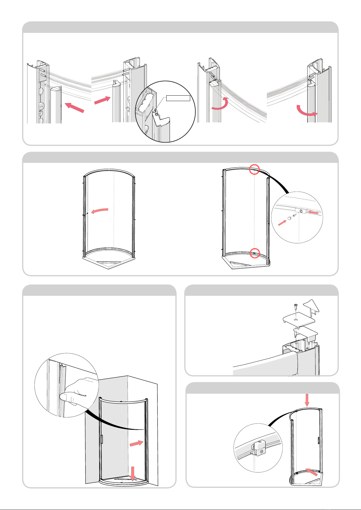
1. Uncoil the two ‘Glazing Wedge Seals (PlexF05),’ Insert the seals to
the outside of the enclosure, between the xed glass panel and lip of
the metal frame, along the vertical side, and also along the bottom edge.
Inserting the glazing seal, starting at top and working downwards, trim
excess length. If tight, lubricate glazing seal with water. Do not stretch
seal when inserting, because, after cutting to length, the seal will shrink
and leave a gap.
If the seal is misshapen, soak in warm water, not boiling, for 2-3 minutes
prior to use.
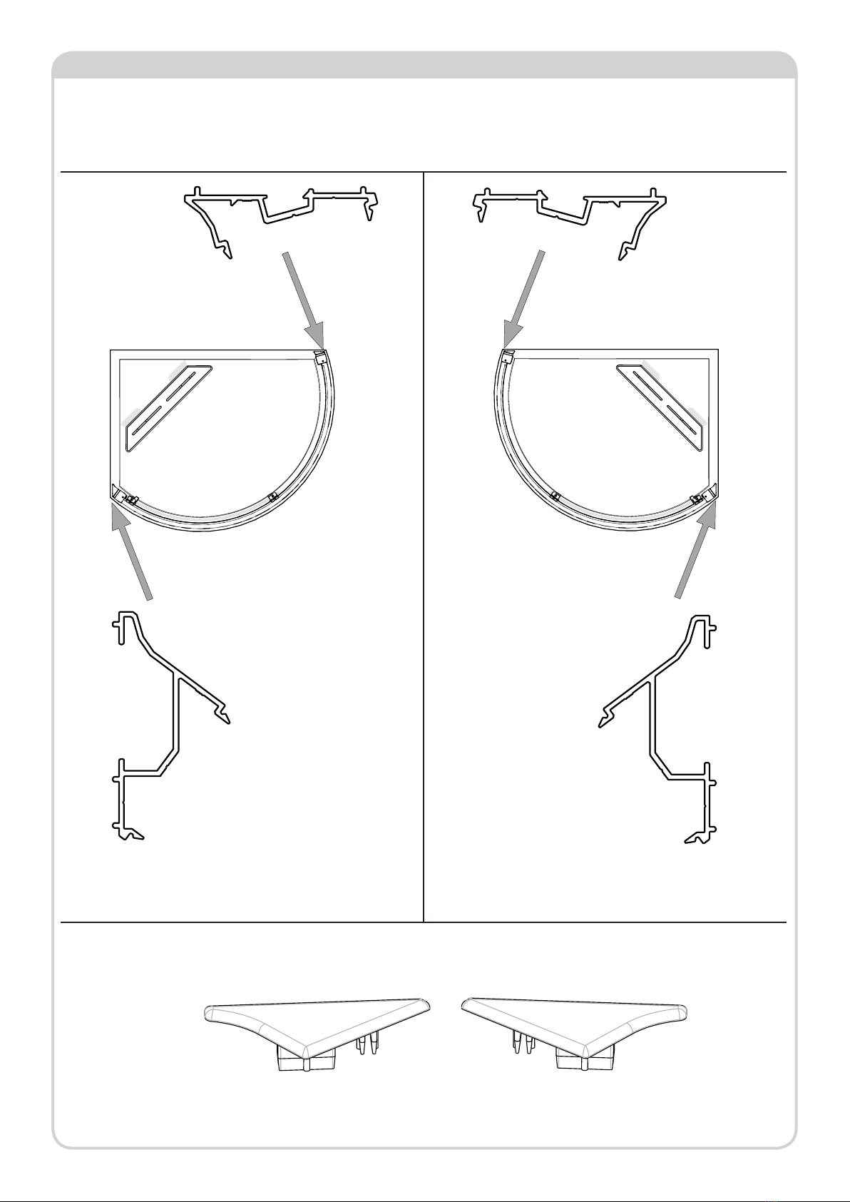
Step 17 - Ret Clip-In Extrusions
2. Relocate the clip-in extrusions down the in side of each post, rotate and
press the clip-in extrusion at top, middle and bottom of each prole, to
gently press-in and reattach the extrusions down each entire length.
1. Replace the clip-in extrusions from Step 5, ensuring left and right are
correctly repositioned. (Handing shown below for example only).
Door Opening Side Fixed Panel Side Door Opening Side Fixed Panel Side
Step 18 - Fit Fixed Glass Panel
1. Carefully t Fixed Glass
Panel into slot in wall-
post, ensuring the panel is
concentric with the rail and
vertical to the wall post. Tap
the plastic prole rmly into
groove of clip-in extrusion
along full length, if this is not
done, the xed panel glass
may interfere with the door
glass when this is installed.
(Handing shown for example
only).
Tip. Use your foot to steady
the bottom of the glass and
prevent it slipping off the
curved rail.
2. Take the Glass Patch Clamp
assemblies (DCM-85-ASM), and
place them at the top and bottom
corners of the glass at the centre of
the enclosure.
Next take the two No.6x12 Phillips
Head screws, pushing the glass as
far round as possible, ensuring the
glass is still concentric to the rails top
and bottom. Tighten the two screws
into the two clamps, ensuring the
screws engage centrally with the
two pre-drilled pilot holes in the
curved rails. Finally, ‘push t’ the
Patch Guide Caps (M276-01) into
the two clamps.
Locate Here
Step 20 - Fit Cover Caps
1. At both top corners, t the inner
‘Comp. Chnl. Top Caps (M56-02)’
followed by the ‘Wall Jamb Top Caps
(M56-01) and the Top Caps left and
right (M73-01 & M73-02) .’ Securing
in place with the No.4x10mm CSK
screws provided.
Step 21 - Fit Glass Door
1. Fit the glass door, by rst lifting the door into
position with both sets of wheels sitting in the top
rail prole. The rail should now take the doors
weight.

7Issue 01 MAR.19
SILICONE ALONG SHIM ONLY
1.Looking from the outside of the enclosure, slide the door into the
closed position, with the glass pushed up against the wall post. Check
the door glass is level with the wall post down the entirety of its edge.
2.If there is an uneven gap, the glass in the door can be adjusted either
up or down at each corner with the rollers. Using ozi-head Screwdriver,
loosen or tighten the bolt located on the top of each roller set. Each
roller has around 6mm of adjustment, clockwise will lower the glass,
anti-clockwise raises the glass.
Step 22 - Adjust Glass
1. On the outside, silicone around all three junctions with the wall and tray, and also
on the frame where the sill meets the uprights. On the inside, only silicone along the
two vertical junctions with the wall, and around the shim.
Step 24 - Silicone
Outside Only
Inside Only
Step 25 - Wait 24hr
1. Allow 24 hours before using the shower.
Do not silicone seal on the inside of
unit (except where shown). Sealing
the wall posts & sills to the tray on the
inside can result in leakage problems-
please note that, in use, water can
penetrate into the frame extrusions-
this has no detrimental effect to the
product- however, this water must be
allowed to drain out of the extrusions
to the inside. Silicone down the wall
posts wall junction, around the shim
and at the bottom between the xed
glass seal and wall post.
2. Turn the two release levers, until
the slots in the rear arms of the
release levers sits onto the bottom
rail edge protrusion, holding the
bottom of the door in-place.
Step 21 - Fit Glass Door (continued) Step 23 - Fit Overlap Seals
16mm
5mm
Bottom Notch
Cut
1. Take the ‘1873 Overlap Seal’ (PlexRF023), and t to the edge of the xed panel,
with the soft ‘skirt’ facing the inside, in order to contact with the sliding door glass.
Make sure the seal is fully sat fully down onto the glass clamp at the bottom of the
xed panel.
2. Fit the 1912mm Overlap
Seal (PlexRF023) to the
inside edge of the sliding
door glass panel, with the
soft n facing the xed panel.
Notch the top and bottom
(approximately 16mm at
the bottom, and 25mm at
the top), to ensure a tight
contact with the glass clamp
at the bottom when in the
closed position.
Table of contents
Other KUDOS Shower Cabin manuals
Popular Shower Cabin manuals by other brands

Insignia
Insignia GT002 installation manual

ERLIT
ERLIT ER4508TP Installation and operation instruction

SANPLAST
SANPLAST ALTUS II KND2/ALT II Series installation guide

Sanotechnik
Sanotechnik SM101 Mounting instruction

Radaway
Radaway Arta KDJ I Assembly instruction

Fleurco
Fleurco ALINA S016 instruction manual