KUDOS Pinnacle 8 CENTREFOLD 800 User manual

1Issue 01 JAN.20
Tools Required
Pozi-head Screwdriver
3mm Allen Key - supplied Cutting Pliers
Clear Silicone Sealant
7mm Masonry Drill Bit
Spirit Level
Tape Measure
Drill (Battery or Mains)
Pencil
Flat-head Screwdriver
INSTALLATION INSTRUCTIONS - CENTREFOLD CORNER
Please read these instructions throughout before installing as incorrect tting will invalidate the guarantee.
If you are unsure about these instructions please contact Kudos Shower Products 01539 564040.
HEALTH & SAFETY WARNING
DUE TO THE WEIGHT & SIZE OF THE GLASS PANEL(s) A MINIMUM OF TWO PERSONS ARE REQUIRED
TO MOVE AND INSTALL THIS ENCLOSURE
For the wall post and xings use only warm soapy water and damp cloth/ sponge
on a regular basis. After cleaning please rinse with clean water to remove any
residue.
Do not use abrasive scouring powders, chemicals or aerosol cleaners - these may
result in damage to the surfaces, in particular, the plated component parts.
The glass panels are pre-treated with Life Shield on the inside surfaces only.
Whilst this makes cleaning the glass easier and helps prevent the build up of
harmful lime-scale and soap deposits, the glass still needs to be maintained on a
regular basis. We recommend the use of a detergent and aroma free glass cleaner
(A 50/50 mix of white vinegar and water works well).
DO NOT use strong detergents, abrasive cleaners or abrasive scrubbing
equipment for cleaning, these can damage the coating.
DO use a squeegee to remove remaining droplets of water from glass after
showering, any build up of residue can be removed easily using an appropriate
cleaner and agitation from soft cleaning equipment.
Cleaning - General
Kudos LifeShield Glass Treatment
Important
Check appearance of all product - any defects must be reported to Kudos Shower
Products before assembly/installation. Claims for imperfections will only be
accepted prior to assembly/installation.
Any claims made under the terms of the Lifetime Guarantee must be reported to
Kudos within 21 days of the fault occurring.
Check the enclosure adjustment sizes are suitable for your installation.
Use care when drilling into the walls to avoid hidden pipes or electric cables.
Stage 2
silicone sealant
Stage 1
Shower Tray
Ensure the top of shower tray is
LEVEL in ALL directions.
Once the tray is installed but
before the wall tiles are tted, any
gap between the tray and the walls
must be lled with silicone sealant
ush with the top of the tray.
Once the walls have been tiled but
before the enclosure is installed,
the tiles must be silicone sealed to
the tray all of the way around in
one continuous bead.
Failure to follow these
instructions will result in
leakage problems.
THESE INSTRUCTIONS ARE TO BE LEFT
WITH THE CONSUMER

2Issue 01 MAR.19
Product Sizes and Adjustments
PRODUCT PACK CODES DIMENSIONS (mm)
CENTRE-FOLD IN-LINE PANEL PACK DOOR PACK A
800 P8CF80P1 P8CF80P2 770 to 790
900 P8CF90P1 P8CF90P2 870 to 890
1000 P8CF100P1 P8CF100P2 970 to 990
PRODUCT PACK CODES DIMENSIONS (mm)
CENTRE-FOLD SIDE PANEL PACK B
800 P8CF2SP80 770 to 790
900 P8CF2SP90 870 to 890
ENCLOSURE HEIGHT
= 2000mm
26mm
A
26mm
A
LEFT HAND INSTALLATION
RIGHT HAND INSTALLATION

3Issue 01 JAN.20
Step 2 - Add Trim to Side Panel
Parts List
Installation Packs
Installation Steps
1 x M193-01
Shim
1 x M305-01
Push-In Seal Pull
Out Tool
1 x FIX-112
4mm Allen Key
2 x No.4x13 CSK
S/S Screws
6 x No.8x30 PH
S/S Screws
6 x 7mm
Wall Plugs
1 x M254-01
No8 Screw Wizard
2 x M224-01
Wallpost Top Cap
2 x
Wall Posts
Step 1 - Install Wall Posts
45mm Deep
30mm Deep
2 x No.6x19 CSK
S/S Screws
1 x FIX-109
2mm Allen Key
2 x SF-BIF-CLMP-998
Rail Clamp
2 x SF-BIF-SLID-998
Centrefold Slider
4 x M6x30 CSK
Hex
1 x M111-03
Installation Spacer
2 x M144-02-AG
Installation Spacer
1 x Rail Left
1 x Rail Right
1 x Door
Assembly
2 x Fixed
Glass Panel
2 x 1940mm
1 x 1926mm
PlexRF-019 Seals
2 x 73mm (800 pack)
2 x 98mm (900, 1000 pack)
1 x 738 (800 Side pack)
1 x 838 (900 Side pack)
WTR-001Trim Seals
1. Position door wall post 21mm in from front edge of the tray,
as shown. Using spirit level to ensure wall post is vertical, mark
through 3 slotted holes per wall post (6 total) onto wall surface.
Remove the post from the tray, placing safely off to one-side.
2. Using a 7mm masonry drill bit and drill (or appropriate drill bit if
drilling tiles), drill six holes using the ‘spot’ marks, each hole should
be 30mm in depth.
3. Insert the six ‘7mm Wall Plugs’ into the six holes. Fix wall post
using 3x No.8 x 30mm long screws provided. Tighten all screws
using pozi-head screwdriver, ensuring the wallpost is vertical.
4. Position side panel wall post 16mm in from front edge of the
tray, as shown. Repeat the above steps.
Insert screw heads into the wizard tool supplied to help locate screws into wall plugs. Then
tighten with pozi head screwdriver.
1. Take note of label on glass ‘This surface
to outside’ this will determine which is the
bottom edge of your installation.
2a. For 800 Side Panel Unit acquire 1 X
736mm Trim Seal.
2b. For 900 Side Panel Unit acquire 1 X
836mm Trim Seal.
3. Peel off a small length of the bottom trim
adhesive tape and apply to bottom of glass
panel from the edge as shown. Continue
along length of trim, peeling away the tape
as you go, until the full trim length is adhered
to the panel.
1 x 1963mm
PlexRF-018-06
Seal
1 x FIX-111
3mm Allen Key
1 x Side Glass
Panel
Step 3 - Fit Side Panel Glass
1. Carefully t glass panel into slot in wall
post, ensuring panel is parallel to tray edge.
2. Secure Panel using the Push-in channel.
Remove the protective sleeve on the
push-in channel extrusion. From inside the
enclosure, place the push-in channel (black
strip towards glass) against the glass. At
this stage don’t need to fully insert. Insert
1/4 at the top to secure glass panel whilst
installing.
Push-in channel can be removed, if
necessary, by inserting tool (M305-01)
supplied to pull the channel out at top.
1 x DCM41-01
Corner Bracket
16mm
21mm
Fitted Seal to outside
Outside
Position of Side Panel wall post
when fitting on showertray
Position of Door Panel wall post
when fitting on showertray
Mark through 6 (2 x 3) total
slotted holes onto the wall
Inside view

4Issue 01 MAR.19
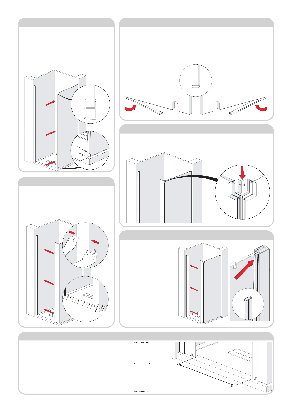
Step 8 - Fit Second Panel Glass
1. Like step 4, carefully t glass panel
into slot in wall post, ensuring panel
is parallel to tray edge.
2. Secure Panel using the remaining
Push-in channel. Remove the
protective sleeve on the push-in
channel extrusion. From inside the
enclosure, place the push-in channel
(black strip towards glass) against the
glass. Again don’t need to fully insert.
Insert 1/4 at the top to secure glass
panel whilst installing.
Push-in channel can be removed, if
necessary, by inserting tool (M305-
01) supplied to pull the channel out
at top.
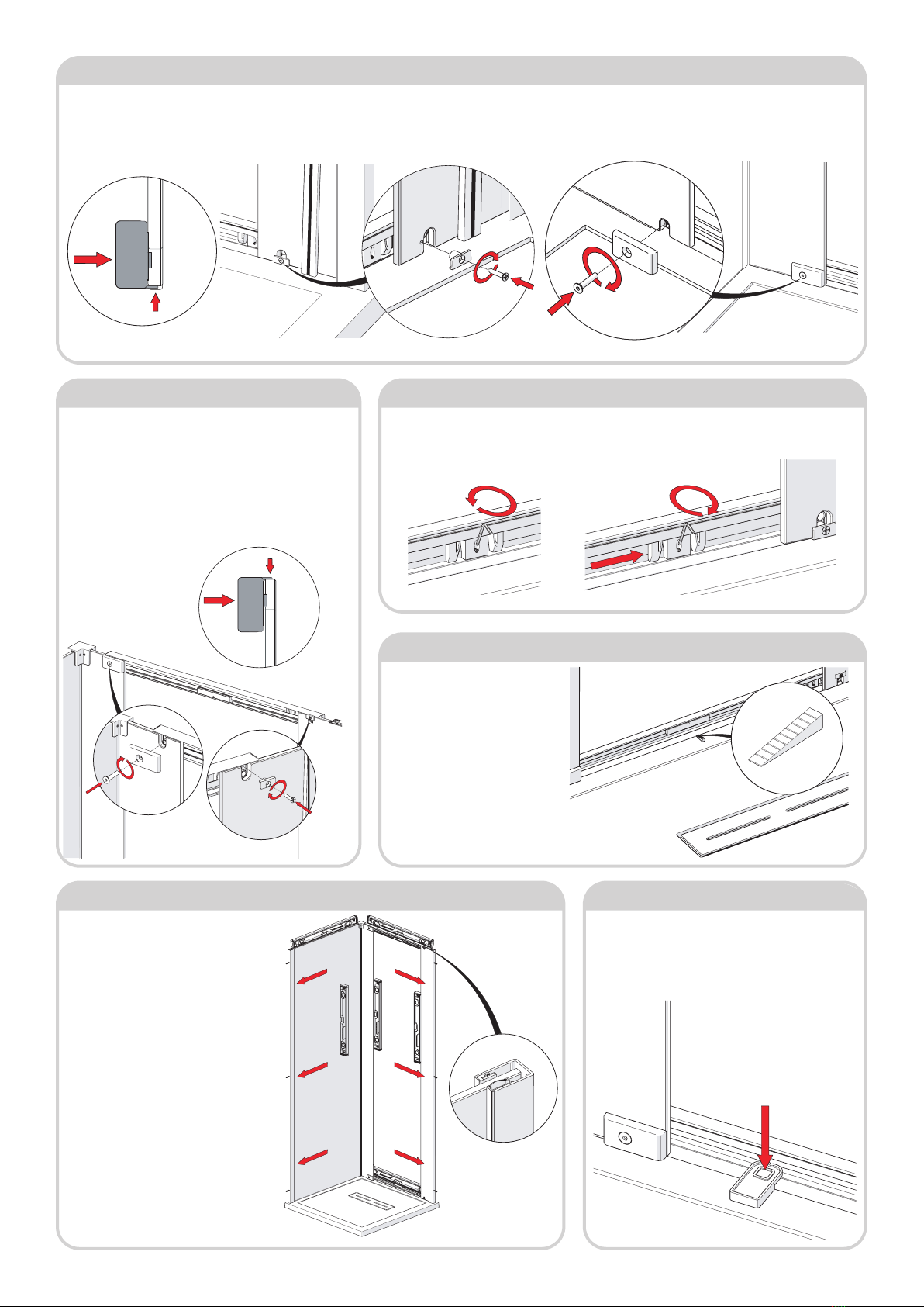
Step 5 - Add Trim to Both Fixed Panels
1. Take note of label on glass ‘This surface to outside’ this will determine which is the bottom
edge of your installation.
2a. For 800 Unit acquire 2 X 73mm Trim Seals.
2b. For 900, 1000 Units acquire 2 X 98mm Trim Seals.
3. Peel off a small length of the bottom trim adhesive tape and apply to bottom of glass panel from
the edge as shown. Continue along length of trim, peeling away the tape as you go, until the full trim
length is adhered to the panel.
Step 7 - Add Corner Bracket
1. Acquire Corner Bracket (DCM41-01) from the Side Panel Pack. As indicated place this over the
top of the two adjoining glass panels. Use the 3mm Allen key to remove/tighten the grub screws to
the xed panels.
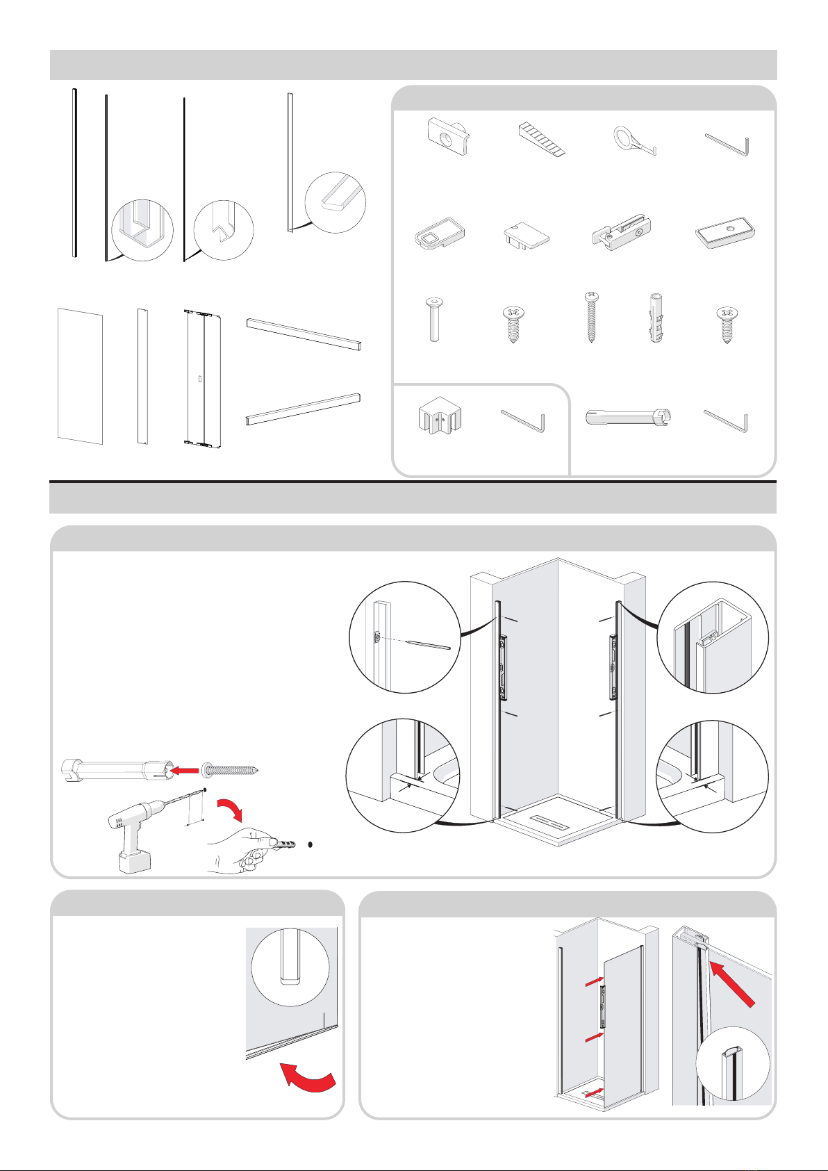
Step 4 - Fit Corner Joint Seal
1. Acquire the PlexRF-018-06 from the Side Panel Pack.
From starting at the bottom, press this over the glass edge
ensuring that it is fully seated over the entire length. Position
as shown. If tight, lubricate corner seal and glass edges with a
damp clean cloth to ease tment - the water will evaporate
over a short period. Do not use silicone spray or any other
substance other than water, these will not fully dry out and
will compromise the grip and rigidity of the joint.
parallel
parallel
Step 6 - Fit Fixed Panel
1. Add xed panel to the Corner Joint seal, make sure it’s the
correct panel. Starting from the top use both hands push the
xed panel into the seal channel. Make sure the panel is fully
inserted all the way though. Adjust side panel/in-line panel
to ensure side panel is parallel to tray edge and the outside
surface of in-line panel is aligned with the surface of gripper
seal in the adjacent ‘door’ wallpost.
Step 9 - Adjust In-line Glass Panels
Xmm
1. Carefully unpack the folding door assembly pack. Unfold the
panels into a straight line and measure the overall width of the
panels then add 11mm to this to give ’X’ dimension.
For example: folding panel width = 631mm + 11mm =
642mm
2. Adjust the xed panel inserted into the wallpost to achieve
the correct ’X’ dimension between both panels. Will need to
remove and re-insert the push-in channel to achieve this. Use
level to ensure xed panel is vertical.
measure
Inside Outside
Inside view
Inside view

5Issue 01 JAN.20
Step 15- Place Spacer
1. Place the small spacer block (M111-03) so that it is
resting on the bottom rail approximately in the position
as shown below. This will be used to rest the door
glass in position while tting.
Step 14 - Fully Insert Push-In Channels
1. Remove the push-in channels previously
inserted in step 3 and 8.
Push-in channel can be removed, by
inserting tool (M305-01) supplied to pull the
channel out at top.
2. Ensure outer edge of the Glass Panels
are vertical, as shown, using spirit level.
Make sure the rails are also level.
3. Fully insert the push-in channel (black
strip towards glass) against the glass,
starting from the bottom, insert into wall
posts. Ensure they are both fully inserted
so that the channel is ush with the surface
of the wall post along the entire height.
Drawn lines on the glass panels
should not be visible beyond
the wallposts after tting
push-in channels.
Step 10 - Fit Bottom Rail to Fixed Panels, Determine Opening Side
1. Acquire one of the rails. Outer extrusion to be on the outside of the glass. Line up the 2 holes on the rail with 2 slot/holes at the bottom of the glass.Ensure ange
on rail is in contact with the bottom edges of the glass panel. Highlighted in the detailed diagram below.
2. Secure the rail with M144-02-AG using No.6x19 CSK. Apply to the end you intend the door to pivot/hinge from. Secure the opposite side with SF-BIF-CLMP-998
using M6x30 CSK.
Step 11 - Fit Top Rail to Fixed Panels
1. Acquire the remaining last rail. Outer extrusion to be on
the outside of the glass. Like step 7, line up the 2 holes on
the rail with 2 slot/holes at the top of the glass. Ensure ange
on rail is in contact with the top edges of the glass panel.
Highlighted in the detailed diagram below.
2. Secure the rail with M144-02-AG using No.6x19 CSK.
Apply to the end you intend the door to pivot/hinge from.
Secure the opposite side with SF-BIF-CLMP-998 using
M6x30 CSK.
Step 12 - Set Guide Stoppers
1. Use the 2mm allen key provided to loosen the guide stopper. Once loosened ‘slide’ to the side
with the M144-02-AG. Re-tighten once the guide is in a position similar to the diagram below. Do
this for both bottom and top rail. Guides need to be on the same side.
Step 12 - Level Bottom Rail
1. Often shower trays have
different angled top faces, in
order to help keep the frame
supported use the ‘Shim (M193-
01)’ supplied. On the inside of
the enclosure measure the gap
between the bottom of the rail
and top of the tray, select the
height required from the shim
strip supplied, break off and
insert under rail. The shim will be
concealed by silicone sealant later.
Inside viewInside view
Inside view
Inside viewInside view
Inside view
Inside view

6Issue 01 MAR.19
Step 18 - Fit the Slides
1a. Carefully lift the folding door
from the packaging and hold as
shown inside the enclosure ready to
offer into position.
a. Rest the side glass of the folding
door on your foot with the folding
door panels slightly opened.
Step 16 - Fitting the door
b. Swing door glass into “at”
position and supporting gass by
hands, remove foot from under
glass, then offer glass into the
opening between the two xed glass
panels. Rest the bottom edge of the
glass on the spacer block.
c. Now slide the glass door into
position central between the two
xed panels so that the central
magnets top and bottom pull the
door glass into the frame. You will
feel the glass held in position by the
magnets when correctly positioned.
Step 17 - Secure Door Assembly
1.In order to position the door correctly, begin by moving the bottom hinge so that the xed
panel glass ts snugly into the corner of the hinge bracket as indicated.
With both hinges held rmly in position against the xed panel glass, t 1 X M6x30 CSK Hex
Screws into the top hinge and fully tighten. Then t 1 X M6x30 CSK Hex Screws into the
bottom hinge and fully tighten. Open the door and discard the spacer block.
1. Acquire SF-BIF-SLID-998 from the installation pack and disassemble. Insert the top slide on
the closing side of the door into the rail by tilting the slide and lowering the rectangular slide
into the track of the rail. Tilt the slide and offer it into the rail as shown.
2. Now push up and into the Slide will run smoothly in the track when correctly tted.
3. Position slide over centre of cut in glass and loosely secure with M6 X 16 Screw, do not fully
tighten at this stage.
4. Repeat the above to t the bottom slide.
Step 19 - Adjust Slide Action
equal
equal
No contact
between rail
and slide
1. The sliding action should be smooth and running freely, If this is
not the case, slacken the bottom slide then position slide as shown
below. Now repeat for the top slide. This ensures there is no
pressure on the rails from the slides.
Position slides as shown below. Slides should be set so as not to
make contact with the rails at the top and bottom.
DIAGRAM OF TOP RAIL AND SLIDE
SHOWING CORRECT SETTING
Note: To allow smooth operation of the guides, apply Vaseline or appropriate lubricant to inside of
both top and bottom rail.
This glass edge
to fit neatly into
the corner of
the hinge here
Inside view
Inside view
Inside view
Inside view
Inside view
Inside view

7Issue 01 JAN.20
Step 21 - Fit Cover Caps
1. At the top of both wall
posts secure and t the Top
Caps (M224-01) with the
No.4x13mm CSK screws
provided.
Step 24 - Wait 24hr
1. Allow 24 hours before using the shower.
Step 23 - Seal the Enclosure
1. On the outside, silicone around all three junctions with the wall and tray,
and also all the way round the bottom rail. On the inside, only silicone along the two vertical
junctions with the wall. And along the shim only if used. Silicone seal where the xed panels
meed the rails, shown below.
2. Do not silicone seal on the inside of unit (except where shown). Sealing the
wall posts & sills to the tray on the inside can result in leakage problems -
please note that, in use, water can penetrate into the frame extrusions- this
has no detrimental effect to the product- however, this water must be allowed to drain out of
the extrusions to the inside. Silicone down the wall posts wall junction.
When installed correctly, Kudos guarentee the enclosure will not leak under normal
showering use, ie. when the shower head is in it’s normal showering position.
N.B. - Using the shower head to clean/rinse down the enclosure does not constitute normal
showering use.
Step 20 - Fitting the Door Seals
1. There are two longer seals (2 x 1940mm) and one shorter (1 x 1926mm) similar to the diagram
shown. The longer seals t the the xed glass panels either side of the door. From starting at the bottom,
press these over the glass ensuring they are fully seated over the entire length between the top and
bottom chrome castings.
2. Next t the door closing seal at centre on the handle side.
Orientated if Hinge
Side is this end.
1 x 1940mm
PlexRF-019
Inside of
enclosure
1 x 1940mm
PlexRF-019
1 x 1926mm
PlexRF-019
Inside of
enclosure
Inside of
enclosure
Step 22 - Adjust Closing Strength
1. The magnetic closing strength of the folding doors
can be reduced if required. Using 2mm allen key
supplied, loosen the grub screw in the top rail magnet
and offset the magnet to one side, then re-tighten grub
screw. Repeat for bottom rail magnet.
Maximum offset adjustment is 10mm.
Inside view
SILICONE ALONG SHIM ONLY
Outside Only
Inside Only
This manual suits for next models
2
Table of contents
Other KUDOS Shower Cabin manuals