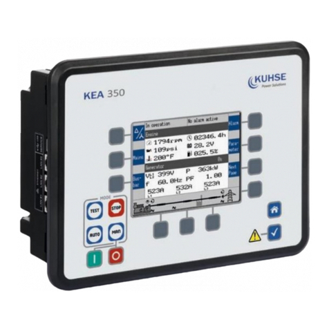
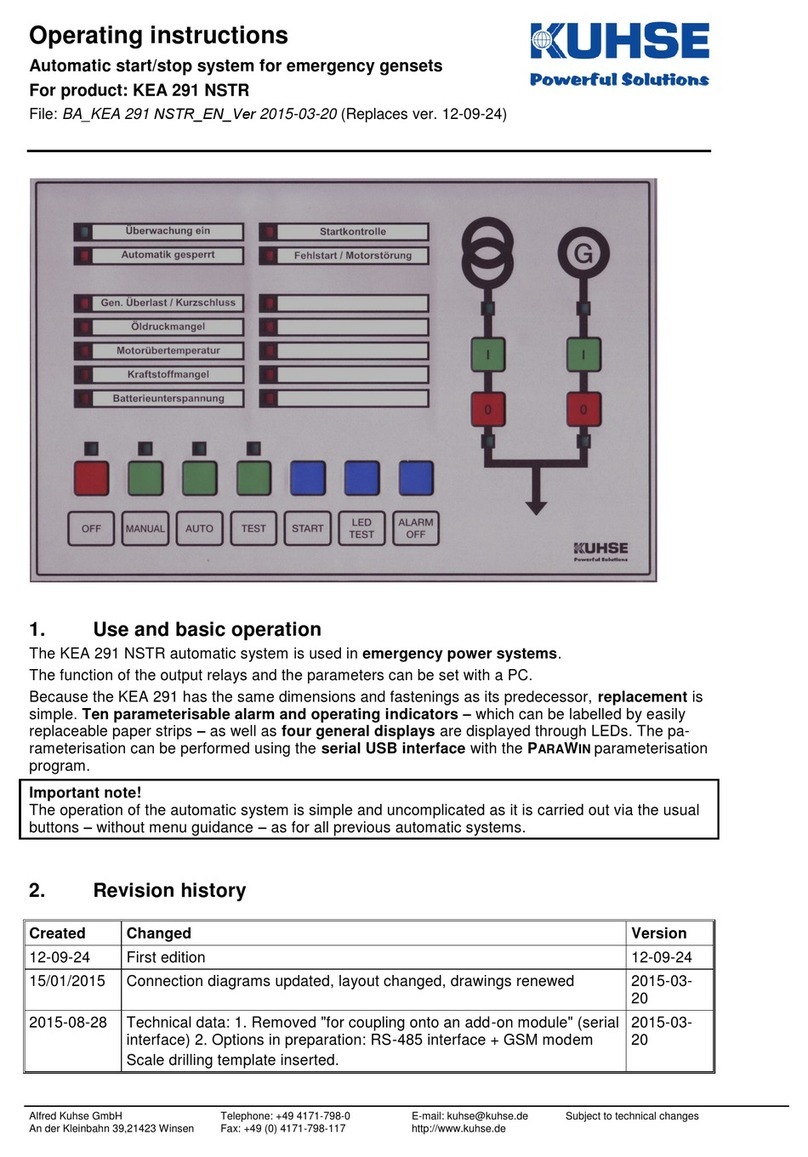
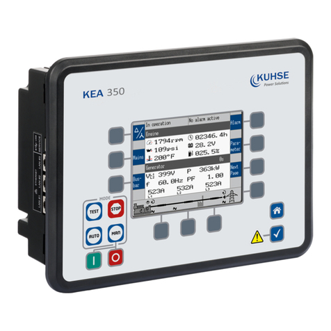
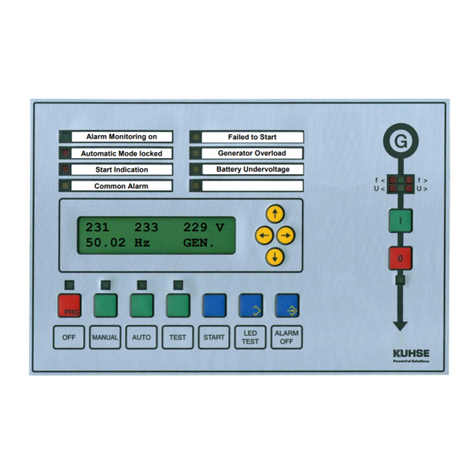
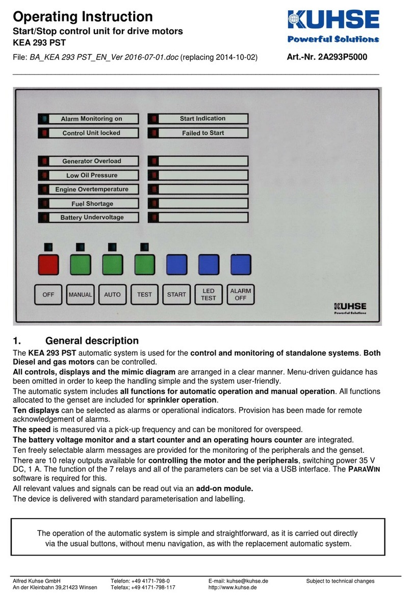
Kuhse KEA 101 NSTR User manual

SA101NX3-E
07-01-25
Replaces: 06-08-08
Service Manual
Start-Stop Control Unit
for Emergency Power plants
KEA 101 NSTR
WARNING NOTES
− Care must be taken when connecting the device, as it may be destroyed if incorrectly connected.
− All details of the connection specifications must be fulfilled.
− The PE(N) must be connected for security reasons to terminal 5 on the X403.
− The leakage current of the noise filters is 22 mA in case of a 2-phase voltage lost.
− Only adequately qualified personnel should undertake the installation and commissioning.
− The relevant regulations, especially the VDE regulations, must be observed.
− The SERVICE MANUAL should be read carefully before commissioning.
− The device must be parameterised in such a way that any risk to persons or property is prevented.
− The charging device must be switched off before the battery is disconnected.
− The negative pole of the battery must be grounded at the input terminal of the switchboard. The
minimum conductor cross-section is 10 mm2.
− The screens of the analogue input wiring must be connected to the earth screws on the KEA cover, and
must have no connection to any other metal parts.
− The supply voltage can be set to 12 or 24 V DC with a switch on the RZ 071-D.
− When the supply voltage of the control unit has been switched off, you must wait at least 20 seconds
before applying it again.
− All coils must be fitted with reverse diodes to prevent high voltage peaks. All other coils or inductive
loads must also be fitted with suppressor elements. The same applies for all relays and inductors that are
used in the switchboard or controlled externally.
− The shielding of the analogue wiring must only be connected the earth screws beside the terminal strip
X 401 and may have no galvanic connection to any other metal parts.
CONTENTS
Design Page 2
Connection Page 2
Operation of the display Page 3
Contrast setting Page 3
PIN number, IDENT-NUMBER Page 3
Parameterisation Page 4
Connection of RZ 071-D Page 5
Technical Data Page 7
Order number codes Page 8
DOCUMENT HISTORY
Revision Modification Released Revision Modification Released
11/2005 First edition 05-11-30
01/2006 Connection of RZ 071-D 06-01-11
06-06-06 Format 06-06-06
06-08-08 Menu structure 06-08-08
07-01-25 Menu structure 07-01-25
Changes without further notice reserved.
Alfred Kuhse GmbH, D-21423 Winsen/Luhe, An der Kleinbahn 39. Phone +49 (0)4171 798-0, Fax +49 (0)4171 798-117, http://www.kuhse.de

SA101NX3-E - 2 / 8 - 07-01-25
DESIGN
The control unit is incorporate into the front door of the switchboard. The front meets the protection class
IP 44 when installed. The two rows of LEDs are marked with interchangeable labels. The relay unit is
mounted on the mounting plate and linked to the control unit in the door with the supplied cable.
The control unit has an optic fibre or USB interface (selected by a toggle switch) for the connection of a PC.
The following settings (password protected) and analogue readouts are possible.
PARAMETERISATION
− Mains voltage monitor,
− Generator voltage and current monitor,
− Text input (consumer defined) for the first 19
alarms and encoding for all alarms,
− Battery monitor,
− Start-stop parameters,
− Speed sensing,
− Mains/generator change-over,
− Relay and output functions,
− Names and limit values for the analogue inputs,
− Frequency control for isolated operation,
− Voltage control for isolated operation,
− General parameters.
ANALOGUE READOUTS
− Actual values:
o Voltages,
o Currents,
o Active and apparent load,
o Power factor,
o Speed,
o Battery voltage,
o Actual values of the four analogue channels.
− Actual status of the digital inputs of the relay unit
RZ 071-D,
− Actual status of the output relays,
− Timers' status.
CONNECTION
− Trained experts may only make the connections of the KEA.
− The PE(N) must be connected for security reasons to terminal 5 on the X403.
− The charging device must be switched off before the battery is disconnected.
− When the supply voltage of the control unit has been switched off, you must wait at least 20
seconds before applying it again.
− The negative pole of the battery must be grounded at the input terminal of the switchboard. The
minimum conductor cross-section is 10 mm2.
− The supply voltage can be set to 12 or 24 V DC with a switch on the RZ 071-D.
− The screens of the analogue input wiring must be connected to the earth screws on the KEA cover,
and must have no connection to any other metal parts.
− All coils must be fitted with reverse diodes to prevent high voltage peaks. All other coils or
inductive loads must also be fitted with suppressor elements. The same applies for all relays and
inductors that are used in the switchboard or controlled externally.
The following signals (if needed) are directly applied to the control unit:
− Voltage of mains and generator,
− Current of generator,
− Four analogue sensors,
− Pick-up,
− Two analogue output signals,
− Optical fibre or USB for parameterisation,
− Two CAN bus systems.
Although the control system is protected against reverse polarity, the correct polarity when connecting the
battery voltage must be strictly observed, as reverse diodes or other electronic parts of the switchboard may
possibly be damaged.
The fuse on the RZ 071-D will be blown, if the control system is connected
with the wrong polarity!
Due to the fact that most of the control relays may be configured for various functions, only the status print
out of the supplied control unit is to be considered as a binding document. It must be observed, that in case of
a possible replacement of a unit, any modifications made after commissioning cannot be taken into account
by the manufacturer.
Changes without further notice reserved.

SA101NX3-E - 3 / 8 - 07-01-25
OPERATION OF THE DISPLAY
Values or parameters are selected, as you would read a book. The further down listed groups are arranged as
'pages'. You can scroll forwards and backwards through these groups by pressing the [→] and [←]keys. The
entries of each group can be read from top to bottom like lines of a text. Select a line by pressing the keys [↓]
(down) and [↑] (up). The selection starts again with the other end of the 'page', when the top or bottom of the
'page' is reached.
Hold down the LED TEST button and press [←] to select directly the ACTUAL VALUES group, hold down
LED TEST and press [→] to display the group CURRENT ALARMS.
To modify a parameter, first enter the relevant IDENT-NUMBER. However, parameters of group 0, -GENERAL
PARAMETERS-, can be modified without entering this number. Parameters are modified as follows:
1. Select the required parameter group with the [←] and [→] buttons. One or two parameters are displayed.
2. Press OFF and LED TEST (function: PARA ON or PARA OFF) together. This opens parameterisation mode
as can be seen by the specific cursor [█]. The selection of the group cannot be changed now.
3. Select the required parameter line (if two are displayed) with the [↓] and [↑] buttons.
4. Press OFF and ALARM OFF (ENTER function) together to select the parameter line. The shape of the cursor
confirms the selection, as it underscores (e.g. 196) now the part of the parameter that is to be modified.
The chosen parameter cannot be deselected now.
5. Select the figure or letter of the parameter that you want to modify with the [←] and [→] cursor keys.
Numerical parameters can be increased or decreased by increments of 1 with the [↑] and [↓] buttons.
Press the same buttons to negate parameters that are displayed with a letter (+/- signs, alarm coding etc.).
6. Press OFF and ALARM OFF together to store the displayed parameter. Press OFF and LED TEST instead of
OFF and ALARM OFF to abort parameterisation.
Display contrast setting
Hold down LED TEST and press key [↑] to increase the display contrast (makes the display darker) or LED
TEST and key [↓] to lower it (makes the display lighter).
PIN Number, Ident-Number
To modify a parameter, you first have to enter the relevant IDENT-NUMBER. This number is compared with
the PIN NUMBER, and if they are identically, the user is authorised to parameterise the device. The user can
chose any PIN NUMBER between 00000 and 50000. The PIN NUMBER and IDENT-NUMBER are factory set to
00000.
A special IDENT-NUMBER can be obtained on enquiry from the factory if you forget your PIN NUMBER, so
that a new PIN NUMBER can be entered. Modify the PIN NUMBER as follows:
− Enter the currently valid IDENT-NUMBER. The pin number is now also shown.
− Enter a new PIN NUMBER.
− The IDENT-NUMBER previously entered is now no longer valid.
The IDENT-NUMBER is deleted 15 minutes after the last input, if the user has not previously set it to an
invalid value.
The automatic deletion of the IDENT-NUMBER is however not carried out while 00000 is set as the PIN.
Changes without further notice reserved.

SA101NX3-E - 4 / 8 - 07-01-25
PARAMETERISATION
Menu structure *)
Group 0 Group 1 Group 2 Group 3 Group 4
KEA 101 NSTR
KUHSE GmbH ACTUAL VALUES
ENCODING OF
ALARMS MAINS VOLTAGE
MONITOR GENERATOR
VOLTAGE MONITOR
COUNTERS
GEN.CURRENT
MONITOR
Group 5 Group 6 Group 7 Group 8 Group 9
ANALOGUE
INPUTS SPEED MONITORING
SPEED GOVERNOR START-STOP
FUNCTIONS PARAMETER FOR
MAINS <> GEN. RELAY / LED
FUNCTIONS
ANALOGUE
OUTPUTS BATTERY VOLTAGE
MONOTOR
ADDITIONAL
PARAMETER
Group 10 Group 11 Group 12 Group 13 Group 14
FREQUENCY CONTROL
VOLTAGE CONTROL ANALOGUE VALUES
VIA CAN THERE ARE NO
CURRENT ALARMS THERE ARE NO
CURRENT ALARMS
*) Since software version 8.
The functions and parameterisation are described in
PA100V00-E, FUNCTIONS AND PARAMETERISATION KEA 101- 112.
This document contains all possible functions featured in the KEA Series 101-112. Please note however, that
only those functions, listed in the Operation manual, are actually implemented. The PARAWIN
parameterisation program also shows only the parameters that are possible for the particular control unit.
Group Function Section in FUNCTION AND PARAMETERISATION
2 Encoding of alarms Alarm monitoring
3 Mains voltage monitor Voltage monitor
4 Generator voltage monitor Voltage monitor
4 Generator current monitor Current monitor
5 Analogue inputs Analogue interface
5 Analogue outputs Analogue interface
6 Speed monitoring, speed governor Speed signals and governor
6 Speed governor Speed signals and governor
7 Start-stop functions Parameter for start and stop
7 Battery voltage monitor Additional parameters
7 Additional parameters Additional parameters
8 Parameters for mains <> generator Transfer mains – generator supply
9 Relay / LED functions Parameterisation of relays
11 Frequency control Synchronisation
11 Voltage control Synchronisation
Connection of KEA and RZ Connection
Operation Manual See TA101NX3-E
Changes without further notice reserved.

SA101NX3-E - 5 / 8 - 07-01-25
CONNECTION OF RELAY UNIT RZ 071-D
The contacts for the terminals 1 to 28 must be connected to [L-] potential. Terminal 29 is provided to be
connected to terminal D+ of the charging dynamo. The "running" signal is active when the voltage exceeds
about 8 volts DC. An AC-dynamo receives the pre-excitation via this terminal.
The functions of several relays may be different, according to their programming. Therefore, the individual
printed status report is valid for a specific control unit.
The stated contact rating of the relays must not be exceeded. Basically is valid, that all operated coils and
inductivities must be provided with reverse diodes (on DC) or with suppressor components matching the
inductivity of the coil.
Terminals 1–14: Input for alarms signals.
Terminal 15: Feed back signal: MAINS IS OFF.
An auxiliary contact (NC) of the mains CB (or contactor) is connected to this terminal. It shows the
position of the breaker. The control unit is fitted with an interlocking circuit which prevents the generator
from switching on as long as the mains is supply on.
Terminal 16: Feed back signal: GENERATOR IS OFF.
An auxiliary contact (NC) of the generator CB (or contactor) is connected to this terminal. It shows the
position of the breaker. The control unit is fitted with an interlocking circuit that prevents the mains from
switching on as long as the generator is supply on.
Terminal 17: Operation mode selection is locked.
The selection of the operation modes by the push-buttons will be locked if a signal is applied at this
terminal. A key-operated switch, to prevent the selected mode from being changed by unauthorised
persons or by mistake, could perform this.
Terminal 18: Remote start with load transfer.
There are two programmable modes for this input: input always active or input only active along with a
mains voltage failure.
If an active command is stated, the start of genset will be initiated and the load will be transferred from
mains to generator supply in the operation mode AUTO.
If the genset is already running in TEST or AUTO mode or was started by the signal REMOTE START
WITHOUT LOAD TRANSFER, the generator will also take over the load.
The load will be switched back to mains supply after the re-connection delay and the genset will be
shutdown (in AUTO) after cooling down period when the signal to this terminal is disconnected (the signal
for REMOTE START WITHOUT LOAD TRANSFER may not be present).
Terminal 19: IMMEDIATE STOP.
The genset will be immediately shut down if a signal is applied to this terminal. The control unit will be
locked for any further starting attempts. To reset the control unit, the operation mode has to be set to OFF.
Resetting is only possible if the signal is no longer connected, otherwise the indicator AUTOMATIC
LOCKED would remain on
Terminal 20: Not used.
This terminal can be used as an alarm input.
Terminal 21: Not used.
This terminal can be used as an alarm input.
Terminal 22: Not used.
This terminal can be used as an alarm input.
Terminal 23: Sprinkler mode.
When a [L-] signal is connected to this terminal the genset starts without changing over to generator
supply and all alarms serve only as a warning ones. If mains fails, the consumers are also switched to
generator supply.
Terminal 24: Start enable input.
Any starting attempt emitted manually or automatically, will be interlocked as long as there is no [L-]
potential connected to terminal no. 24. It is therefore possible to incorporate relevant pre-start conditions
before a signal is given to the starter motor for cranking. If this function is not used, a wire jumper from
[L-] to terminal no. 24 has to be connected.
Changes without further notice reserved.

SA101NX3-E - 6 / 8 - 07-01-25
This function does not meet the requirements of the German Standards DIN VDE 0107, because a
running genset will not be shut down; this function only protects the engine before start-up.
Terminal 25: Remote start without load transfer.
The genset starts in the automatic mode without the generator being switched on when a command is
issued to this terminal. The generator breaker will only be switched on if a command is also issued to
terminal 18 or mains fails. To switch off the generator breaker again, both signals (terminals 18 and 25)
must be cut!
Terminal 26: External command :GENERATOR OFF
If a command is applied here, the generator CB is immediately switched off and remains off as long as
the signal is applied.
Terminal 27: Not used.
This terminal can be used as an alarm input.
Terminal 28: Not used.
This terminal can be used as an alarm input.
Terminal 29: Charging Dynamo, terminal D+.
Terminal D+ of the charging dynamo, if present, has to be connected here. An AC-dynamo receives the
pre-excitation via this connection, and the [+] signal of the dynamo will cause the starter motor to be
switched off.
Changes without further notice reserved.

SA101NX3-E - 7 / 8 - 07-01-25
Changes without further notice reserved.
TECHNICAL DATA
KEA Controller
− Device for frontal installation, dimensions: (⇒,⇑, depth) 260 x 170 x 100 mm,
− Weight approx. 2.2 kg, can be installed wherever required,
− Protection class (installed) IP 44,
− Ambient temperature: Storage -20°C ... +70°C, Operation 0°C … +55°C
− Supply voltage convertible 9-12-15V or 14-24-35V DC,
− 3 customer defined relays, 35 V DC, 1 A. (e.g. for acoustic signallers),
− Standards/regulations VDE 100, Part 710.
Analogue Inputs and Outputs
− 3-phase mains and generator voltage monitor. They can be set in increments of 1 Volt. If the rotary field
is incorrect, the display shows <U.
U
Nom 230/400 volts. They can be set from 50 to 300 volts. Accuracy class 1.
− Mains and generator frequency monitor 50 or 60 Hz. They can be set to any value between 40 and 70 Hz.
Accuracy class 1.
− 3-phase generator current monitor. Accuracy class 1.
− INom 5 Amp: measuring range 0.1 – 15 Amp. It can be set in increments of 20 mA.
− Battery voltage monitor.
− Input for pick-up.
Options:
− Four analogue inputs, which can be fitted with interface cards for
ο PT 100 / PT1000,
ο Current loops,
ο 0 - 10 V DC,
ο Thermocouple NiCr-Ni,
ο Temperature and pressure: VDO sensor,
ο Battery charging current*.
− Two analogue outputs 0 – 20 mA or 0 – 10 V.
*)Under development.
Relay unit RZ 071-D:
− Device for attachment on a mounting rail, dimensions: (⇒,⇑, depth) 300 x 100 x 90 mm,
− Weight approx. 0.7 kg, can be installed wherever required,
− Protection class IP 00,
− Fitted with:
o Input for charging dynamo D+ with pre-excitation for AC alternators,
o 14 ports for alarm contacts,
o 14 general control inputs,
o 12 relays, of which 8 can be configured, contact load:
2 relays max. 35 V, 20 A DC, 10 relays 250 V AC, 6 A.
Relay unit RZ 071-E
− Device for attachment on a mounting rail, dimensions: (⇒,⇑, depth) 210 x 100 x 50 mm,
− Weight approx. 0.5 kg, can be installed wherever required, protection class IP 00,
− Fitted with 15 relays, of which 14 can be configured, contact load max. 250 V AC, 6 Amps.
Serial interfaces
Optical fibre or USB interface (selected by a toggle switch) for parameterisation.
− CAN bus interface to a Common Control Panel.
− CAN bus interface to engine management (the protocol must be known and implemented)
Options:
− Modem (analogue, ISDN, GSM),
− Bus connection to other systems, for example via Profibus.

SA101NX3-E - 8 / 8 - 07-01-25
ORDER NUMBER CODES
Order number 2A101 F UI
Mains Generator
3 x 100 Volt 3 x 100 Volt N 1
3 x 100 Volt 230/400 Volt N 2
3 x 100 Volt 3 x 400 Volt N 3
230/400 Volt 3 x 100 Volt N 4
230/400 Volt 230/400 Volt N 5
230/400 Volt 3 x 400 Volt N 6
3 x 400 Volt 3 x 100 Volt N 7
3 x 400 Volt 230/400 Volt N 8
3 x 400 Volt 3 x 400 Volt N 9
Special voltage or frequency N 0
CT ../1 A N 2
CT ../5 A N 3
Special voltage or current measurement N 0
Example:
Control unit for emergency power plants,
mains and generator voltage 230/400 V,
current transformer of generator ../5 A:
The order number is 2A101N53
Changes without further notice reserved.
Table of contents
Other Kuhse Control Unit manuals