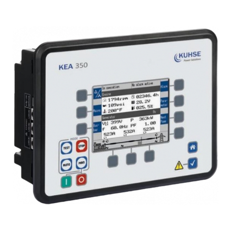
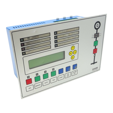
Kuhse KEA 350 P2 User manual

Kuhse Power Solutions GmbH
An der Kleinbahn 39
21423 Winsen | Germany
Fon +49. 4171.798.0
Fax +49. 4171.798.117
www.kuhse.de
BA-KEA 350 P2 / KEA 350 RP-P2_EN Version 03
USER MANUAL
KEA 350 P2 / KEA 350 RP-P2

User Manual
KEA 350 P2 / KEA 350 RP-P2
BA-KEA 350 P2 / KEA 350 RP-P2_EN Version 03
Datum: 17.Sep.2020
Seite 2 von 23
Content
1 Amendments.................................................................................................................................2
2 Brief Overview...............................................................................................................................3
2.1 Terminal Allocation.......................................................................................................................6
2.2 Wiring Diagram .............................................................................................................................6
3 Front Panel Access ........................................................................................................................9
3.1.1 Basic Navigation............................................................................................................................9
3.1.2 The HOME Screen .......................................................................................................................13
4 Operation....................................................................................................................................15
4.1 Power ON....................................................................................................................................16
4.2 Change Operating Modes ...........................................................................................................17
4.2.1 Operating Mode STOP ................................................................................................................17
4.2.2 Operating Mode MANUAL..........................................................................................................19
4.2.3 Operating Mode AUTOMATIC.....................................................................................................21
4.2.4 Operating Mode TEST .................................................................................................................22
4.3 Restore Language Setting via HMI, Buttons and Softkeys..........................................................22
1Amendments
2019-10-16
Creation
Twesten
2020-05-25
Layout adjustment
Twesten
2020-09-17
Implementation of QR Code
Twesten
Created
Amendments
Name

User Manual
KEA 350 P2 / KEA 350 RP-P2
BA-KEA 350 P2 / KEA 350 RP-P2_EN Version 03
Datum: 17.Sep.2020
Seite 3 von 23
2Brief Overview
Fig. 1: KEA 350 RP-P2 Series
Fig. 2: KEA 350 P2 Series
1Terminal 21-40: Mains/Generator/Busbar
voltage
2Terminal 1-20: Mains/GND current, Generator
current, Analog inputs/outputs
3Terminal 101-120: Analog Input 10, Analog
Out‐puts 3-6, Busbar Voltage L3/N
4Terminal 81-100: Transistor Output SO1,
Analog Inputs 4-9
5RS-485 interface RS-485 #1
6CAN bus interface CAN #2
7CAN bus interface CAN #3
8CAN bus interface CAN #1
9Terminal 141-160: Discrete Outputs 13-23,
Transistor Output SO2
10 Terminal 61-80: Discrete inputs, MPU, power
supply, and D+
11 Terminal 121-140: Relay outputs 13-22
12 Terminal 41-60: Relay outputs 01-12
13 USB interface (2.0, slave) SERVICE port
14 ETHERNET interface (RJ-45) LAN C
15 ETHERNET interface (RJ-45) LAN B
16 ETHERNET interface (RJ-45) LAN A

User Manual
KEA 350 P2 / KEA 350 RP-P2
BA-KEA 350 P2 / KEA 350 RP-P2_EN Version 03
Datum: 17.Sep.2020
Seite 4 von 23
The KEA 3X0 series are control units for engine-generator system management applications. The control units
can be used in applications such as: co-generation, stand-by, AMF, peak shaving, import/export or distributed
generation.
The KEA 3X0 series is also applicable for islanded, island parallel, mains parallel and multiple unit mains parallel
operations.
Scope of delivery
The following parts are included in the scope of delivery. Please check prior to the installation that all parts are
present.
Fig. 3: Scope of delivery - schematic
A/B KEA 350 RP-P2(sheet metal housing ) or KEA 350
P2 (-LT) genset control (plastic housing).
All screwable terminal connectors are delivered
with plug and jack.
CQR Code (Link to configuration software and
manual)
C and D with plastic housing KEA 350 P2
(-LT) only:
DClamp fastener installation material - 4 x
EScrew kit installation material - 12 x
FPrinted QR Code sticker - 2 x)
Configuration files and Technical Manual are available at the CD-ROM and
additionally on device internal memory. Opening USB connection to the KEA
3X0 offers read access to the files listed below but with status "delivery" -
please be aware that this files are not updated. Please contact Kuhse for the
latest versions.

User Manual
KEA 350 P2 / KEA 350 RP-P2
BA-KEA 350 P2 / KEA 350 RP-P2_EN Version 03
Datum: 17.Sep.2020
Seite 5 von 23
Files stored at KEA 3X0 device:
–Configuration
–msi-file (installing application files and ToolKit)
–eds-file (zipped)
–Documentation
–Technical Manual (PDF)

User Manual
KEA 350 P2 / KEA 350 RP-P2
BA-KEA 350 P2 / KEA 350 RP-P2_EN Version 03
Datum: 17.Sep.2020
Seite 6 von 23
2.1 Terminal Allocation
Fig. 4: Terminals KEA 350-P2(-LT) plastic housing
Fig. 5: Terminals KEA 350-P2 sheet metal housing
2.2 Wiring Diagram
The Protective Earth terminal 61 is not connected on the sheet metal
housing.
-Use the protective earth (PE) connector located at the bottom center of
the sheet metal housing instead.

User Manual
KEA 350 P2 / KEA 350 RP-P2
BA-KEA 350 P2 / KEA 350 RP-P2_EN Version 03
Datum: 17.Sep.2020
Seite 7 von 23
Fig. 6: Wiring diagram 1(2) KEA 350 RP-P2 / KEA 350 P2(-LT)
Pin 61: Metal housing: don´t use; Plastic housing with HMI/display: Earth/ground

User Manual
KEA 350 P2 / KEA 350 RP-P2
BA-KEA 350 P2 / KEA 350 RP-P2_EN Version 03
Datum: 17.Sep.2020
Seite 8 von 23
Fig. 7: Wiring diagram 2(2) KEA 350 RP-P2 / KEA 350 P2(-LT)

User Manual
KEA 350 P2 / KEA 350 RP-P2
BA-KEA 350 P2 / KEA 350 RP-P2_EN Version 03
Datum: 17.Sep.2020
Seite 9 von 23
3Front Panel Access
The following chapters only apply to model with front panel and display.
Front Panel / HMI / display
Please see chapter for detailed description of the front panel with display and buttons.
Buttons can be disabled by ToolKit with parameter 12978
p. 163/ S. 1038 “Lock keypad”.
3.1.1 Basic Navigation
Main screen
After power-up the control unit displays the main screen / HOME screen (Fig. 8).
The main screen can be divided into the following basic sections:
Fig. 8: Main screen
1Values
2Status Messages
3Alarm Messages
4Single Line Diagram
5Current Softkey Functions

User Manual
KEA 350 P2 / KEA 350 RP-P2
BA-KEA 350 P2 / KEA 350 RP-P2_EN Version 03
Datum: 17.Sep.2020
Seite 10 von 23
Values [1]
The "values" section (Fig. 83/1) of the screen illustrates all measured power related information including
voltages, currents, frequencies, power, and power factor values.
If the mains data display is disabled, the main screen will only show
generator data with bigger digits.
The section's content changes based on the selected sub-menu screen. For
information on specialized menu screens refer to
Chapter 4.1.5 “Specialized Menu Screens” on page 121.
Status messages [2]
The "status message" section (Fig. 83/2) of the screen shows the actual operating information.
For a list of all operation states refer to Chapter 9.5.3 “Status Messages” on
page 1079.
Alarm messages [3]
The "alarm message" section (Fig. 83/3) of the screen shows the last alarm message that is occurred and not
yet acknowledged.
For a list of all alarm messages refer to Chapter 9.5.4.2 “Alarm Messages” on
page 1084.
Single line diagram [4]
The single line diagram (Fig. 83/4) shows the current status of the engine and power circuit breakers.
This section is also used for manual operation of the genset. For additional
information refer to Chapter 5.2.2 “Operating Mode MANUAL” on page 572.
Softkeys [5]
The softkeys (Fig. 83/5) permit navigation between screens, levels and functions as well as configuration and
operation.
Group
Softkey
Caption
Description
Display
Display Mode
Next step to display all measured (delta/wye) voltages one after
the other.
Customer configurable
screen 1 (and 2)
Change to "customer specific screen 1 (or 2)"
Notes
The name of this softbuttons is configurable, too.

User Manual
KEA 350 P2 / KEA 350 RP-P2
BA-KEA 350 P2 / KEA 350 RP-P2_EN Version 03
Datum: 17.Sep.2020
Seite 11 von 23
Group
Softkey
Caption
Description
CAN 1
Change to "CAN interface 1 state" screen.
CAN 2
Change to "CAN interface 2 state" screen.
Ext. I/O
Change to external discrete I/Os screen.
Int. I/O
Change to internal discrete I/Os screen.
Reset Value Display
Reset Maintenance
Reset the maximum value display.
Reset the maintenance counter.
Operation
Increase Value
Increase selected value.
Decrease Value
Decrease selected value.
Confirm Input
Confirm and store changed value.
Acknowledge Message
Acknowledge/Delete message/event.
Open Breaker
Open mains/generator breaker (MANUAL mode).
Close Breaker
Close mains/generator breaker (MANUAL mode).
Code req.
Request a blink code for one error message from the ECU.
Repeated pressing of this softkey displays all stored error mes‐
sages (J1939 Special Screen).
Reset
Reset the blink code (J1939 Special Screen).
Navigation
Move Up
Select previous value/entry.
Move Down
Select next value/entry.
Move Cursor Position
Move cursor position
Return
Return to previous menu.
Next Page
Go to following page/screen of the current menu.
Parameter Screen
Show parameter screen.
Alarm Screen
Show alarm screen.

User Manual
KEA 350 P2 / KEA 350 RP-P2
BA-KEA 350 P2 / KEA 350 RP-P2_EN Version 03
Datum: 17.Sep.2020
Seite 12 von 23
Status symbols
Menu screen
Symbol
Caption
Description
Main Screen
Voltage Display Mode
The index of the symbol indicates whether delta or wye voltage is
displayed and which phases are displayed.
Single Line Dia- gram
Rotating Field CW
Generator, mains or busbar rotating field moves clockwise.
Rotating Field CCW
Generator, mains or busbar rotating field moves counter-clock-
wise.
Power Detected
Power is detected at the respective measuring point (generator, busbar
or mains).
Monitoring Enabled
Indicates that the engine delayed monitoring has expired and the
monitoring functions are enabled.
Power Imported
Power is imported (at mains interchange).
Power Exported
Power is exported (at mains interchange).
Alarm List
Alarm Condition Present
Indicates that corresponding alarm condition is still present.
Alarm class A/B/C/D/E/F present
Symbol with "!" indicates that an alarm of class A/B/C/D/E/F is present.
Alarm class A/B/C/D/E/F not
present
Symbol without "!" indicates that an alarm of class A/B/C/D/E/F is not
present.
Setpoints
Generator Power
Indicates the generator power (actual value).
Mains Power
Indicates the mains power (actual value).
Synchroscope
Phase Angle
Indicates the actual phase angle between busbar and mains or busbar
and generator.
Sequencing
Breaker Closed
GCB of respective genset in sequence is closed.
Breaker Open
GCB of respective genset in sequence is open.
Add-on
Generator is becoming "Add-on" to the (multiple) genset system.
Add-off
Generator is going "Add-off" from the (multiple) genset system.
LogicsManager
Delay ON
Delay before output becomes TRUE.
Delay OFF
Delay before output becomes FALSE.
TRUE/enabled
Variable is TRUE (LogicsManager).
The bit is enabled (CAN Interface).
Relay activated (DiscreteOutputs)
FALSE/disabled
Variable is FALSE (LogicsManager).
The bit is disabled (CAN Interface).
Relay deactivated (Discrete Outputs)

User Manual
KEA 350 P2 / KEA 350 RP-P2
BA-KEA 350 P2 / KEA 350 RP-P2_EN Version 03
Datum: 17.Sep.2020
Seite 13 von 23
The following chapters list notes related to the specific menu screens.
For information on standard softkeys and status symbols refer to Chapter
4.1.1 “Basic Navigation” on page 112.
3.1.2 The HOME Screen
General notes
The “Home” button is a one-click way back to the overview
starting point: the HOME page / HOME screen
The “Home Screen” offers display alternatives via parameter
4103 p. 163 “ Home screen data”
-Generator
-Generator/Mains
-Generator/Busbar
-Generator/Engine
-Generator/LS-5
-Generator/Mains (LS5)
To display the single line diagram with/without mains is select‐
able via parameter 4129 p. 163 “Oneline diagram with mains”
Two customizable buttons enable selection of indications to
display engine and auxiliary values (full access via ToolKit,
name/description cannot be changed via HMI)
Find menu: “Parameter Configure HMI
Configure customer screen x”
Two display brightness levels can be switched by LogicsManager.
Can be used for e.g.:
-Key activation determined
-Brightness reduction on navigation bridge (vessels)
-Saving energy
Find menu: “Parameter Configure HMI
Configure display”
Lock keypad function is determined by LogicsManager 12978 p.
163/ p. 1038. Result is available as logical command variable
11924 p. 1017/ p. 1028 (and can be used with 86.30).
Find menu (ToolKit only!): “Parameter Configure HMI
Configure display”
Fig. 8: HOME page/screen

User Manual
KEA 350 P2 / KEA 350 RP-P2
BA-KEA 350 P2 / KEA 350 RP-P2_EN Version 03
Datum: 17.Sep.2020
Seite 14 von 23
Display alternatives
The HOME screen allows a number of pre-selectable and soft‐button controlled display variants.
Generator
-Voltages (pp - pn) - selectable via softbutton [1]
-Power
-Power Factor PF
-Frequency
-Currents (L1, L2, L3)
Generator/Mains
-Generator values as described above and additionally for Mains
-Voltage
-Frequency
-Current
-Power
-Power factor
Generator/Busbar
-Generator values as described above and additionally for Busbar
-Voltage
-Power
-Frequency
Generator/Engines
-Generator values as described above and additionally for Engine
-Engine speed (rpm)
-Oil pressure (bar or psi)
-Water temperature (°C or °F)
-Operating hours (h)
-Battery voltage (V)
-Fuel level (%)
Generator/LS-5
-Generator values as described above and additionally for LS-5
-Voltage
-Power
-Frequency

User Manual
KEA 350 P2 / KEA 350 RP-P2
BA-KEA 350 P2 / KEA 350 RP-P2_EN Version 03
Datum: 17.Sep.2020
Seite 15 von 23
Generator/Mains (LS5)
-Generator values as described above
and additionally for mains values measured by LS-5, if an application mode (parameter 3444 p. 251)
with L-MCB is selected.
-Voltage
-Power
-Frequency
Fig. 9: AnalogManagers for "Engine" values at Home Screen
Engines" parameter selection
The values to be displayed at "Engines" can be selected via AnalogManager
definition of the parameters at “Parameter
Configure HMI
Screen configuration”. Menu texts and symbols cannot be changed!
4Operation
In operation the genset controller can be manually or remote controlled.
Front panel access is described in chapter 4.1 “Front Panel Access” on page 112.
Access via ToolKit is described in chapter 4.2.6 “View And Set Values In ToolKit” on page 147.
Access via Remote Panel RP 300 is described in chapter and the Technical Manual “37593 RP 300” .
Access via PLC depends on the interface and the data telegram used for communication.
For menu structure/menu tree see “Menu structure (menu tree)” on page
110.

User Manual
KEA 350 P2 / KEA 350 RP-P2
BA-KEA 350 P2 / KEA 350 RP-P2_EN Version 03
Datum: 17.Sep.2020
Seite 16 von 23
4.1 Power ON
Behavior during starting KEA 3X0
The start-up procedure of the KEA 3X0 device can be caused by the following reasons:
Power ON
Power cycling e.g. by 1701 p. 181 “ Set factory default values”
Power is back after voltage drop
This process is visualized by the HMI of the plastic housing version or the LEDs of the metal housing version.
Using the USB Service Port
With power ON and a PC/laptop connected via USB service port it can
happen that the USB window that pops up doesn't show all files and/or the
correct available free memory at the device: Please unplug/plug the USB
connection after the KEA finished starting.
With power ON and connected USB service port it can happen that a
connected USB device is not detected correctly: Please unplug/plug the USB
connection after the KEA finished starting.
With power cycle of the KEA 3X0 the USB connection is lost: Please
unplug/plug and/or start USB connection again after the KEA finished
starting.
... starting plastic housing (HMI) version
Power ON from zero power
Buttons are illuminated
Start-up screen appears
-the red bar at the bottom monitors the degree of fulfillment
HOME screen appears with measured values and state information
-Illumination of buttons is disabled according to the default settings STOP button still might be
illuminated
-WARNING triangle is blinking if there are unacknowledged alarm messages
Power cycling
Warning LED is twinkling in a high frequency
(afterwards the standard process of Power ON is executed:)
Buttons are illuminated
Start-up screen appears
-the red bar at the bottom monitors the degree of fulfillment
HOME screen appears with the same measured values and state information as before power cycling
... starting metal housing version

User Manual
KEA 350 P2 / KEA 350 RP-P2
BA-KEA 350 P2 / KEA 350 RP-P2_EN Version 03
Datum: 17.Sep.2020
Seite 17 von 23
Power ON from zero power
LEDs are twinkling
LEDs are illuminated according to the state of the genset control
Power cycling
Warning LED is twinkling in a high frequency
(afterwards the standard process of Power ON is executed:)
LEDs are twinkling
LEDs are illuminated according to the state of the genset control
4.2 Change Operating Modes
Startup
The genset controls starts in the operating mode defined by parameter 1795 [Startup in mode]. Refer to
Chapter 4.4.5. “Configure Operation Modes” on page 338 for details.
Select Operation Mode
Operation modes can be selected via
front panel buttons (plastic housing variant or Remote Panel RP 300 or VNC client),
HMI configuration (plastic housing variant or Remote Panel RP 300 or VNC client),
remote settings via interfaces, or
ToolKit
The following chapters describe the manually front panel access.
4.2.1 Operating Mode STOP
Usage
Use the STOP button to activate operating mode STOP.
Observe the notes on the system's reaction upon activation of operating mode
STOP as listed below.
STOP LED is illuminated at the front panel; ToolKit home page shows STOP icon left beside the prime mover.
System reaction
In operating mode STOP neither the engine nor the GCB can be operated. Dependent on the application mode
the power circuit breakers cannot be operated.

User Manual
KEA 350 P2 / KEA 350 RP-P2
BA-KEA 350 P2 / KEA 350 RP-P2_EN Version 03
Datum: 17.Sep.2020
Seite 18 von 23
CAUTION!
Hazards due to improper use of operating mode STOP
Selecting the operating mode STOP is not the same as an EMERGENCY STOP.
In some cases the KEA will perform additional logic functions, such as an
engine cool down period, before the engine is stopped.
-For emergency stop functionality use an EMERGENCY STOP discrete
input, programmed as an F class alarm.
If the operating mode STOP is selected while the engine was already stopped the following applies:
The GCB will not be closed.
The fuel solenoid relay will not be enabled.
The start request is ignored.
The start push buttons (softkeys) are disabled.
The engine/generator monitoring remains activated (exception: all monitoring that is delayed by the
engine speed).
If the operating mode STOP is selected while the engine was running the following applies:
Dependent on the current application mode a soft shut down will be executed.
Pressing the STOP button again opens the GCB.
If the STOP button is pressed again, the cool down will be interrupted.
If the operating mode STOP is selected while the engine performs a cool down the following applies:
Pressing the STOP button again causes an immediate stop of the cool down and stops the engine.
If the conditions of the LogicsManager function "Enable MCB" (parameter
12923 p. 263/ p. 1038) are TRUE, the MCB will be closed again if it is open in
STOP operating mode.

User Manual
KEA 350 P2 / KEA 350 RP-P2
BA-KEA 350 P2 / KEA 350 RP-P2_EN Version 03
Datum: 17.Sep.2020
Seite 19 von 23
4.2.2 Operating Mode MANUAL
General usage
In the MANUAL operating mode (mode button “MAN” illuminated) both the engine circuit breaker and the
power circuit breaker can be operated via the push buttons along the bottom of the display (softkeys).
Additionally the Start(I)/Stop(O) buttons can be used to start or stop the engine.
1 Mode button: MAN
2 START button: Engine
3 STOP button: Engine
4…6 Soft buttons: Breaker OPEN/CLOSE
Fig. 10: KEA 3X0 MAN-buttons
Use the mode button “MAN” to activate operating mode MANUAL.
The MAN button is illuminated.
The breakers will open immediately without power reduction. To open the
breaker in a no-load condition, reduce the load manually in the setpoints
screen (Chapter 4.1.5 “Specialized Menu Screens” on page 121).
Example for application mode A01
To start the engine:
Press the button [I] below the MAN button.
Success: The engine starts and the circular arrow and the eye symbol appear.
Failure: No change in the display until the "start failure" message appears.
To stop the engine:
Press the button [0] right below the MAN button.
Success: The engine stops and the circular arrow and the eye symbol disappear.
Failure: No change in the display until the "stop failure" message appears.

User Manual
KEA 350 P2 / KEA 350 RP-P2
BA-KEA 350 P2 / KEA 350 RP-P2_EN Version 03
Datum: 17.Sep.2020
Seite 20 von 23
Overview
Function/Status
Symbol
Available in application mode
Start/running
engine
/
Stop/stand still
engine
/
Breaker open
command is
issued or a clo‐
sure of the
breaker is
blocked
No defined
breaker state
Open the GCB
Close the GCB
Open the GGB1
Close the GGB1
Open the MCB
Close the MCB
1The GGB can not be operated via softkey.
This manual suits for next models
1
Table of contents
Other Kuhse Control Unit manuals
Popular Control Unit manuals by other brands

TECshow
TECshow MATRIXCOB LITE user manual

Haier
Haier YR-H71 Service manual

Toshiba
Toshiba TOSVERT VF-A7 instruction manual

Sophos
Sophos SG 105wSG 105XG 105wXG 105SG 115SG 115wXG 115XG 115wSG 125SG 125wXG 125XG 125wSG 135SG 135wXG 135XG... Mounting instructions

RWC
RWC 315i Installation and maintenance instructions

Zeta
Zeta SMART CONNECT SCM-ACM instruction manual