Operating Instruction KEA 293 PST - 6 / 12 - File: BA_KEA 293 PST_EN_Ver 2016-07-01.doc
Subject to technical changes
An der Kleinbahn 39,21423 Winsen
Telefax; +49 4171-798-117
AUXILIARY DRIVES signal is present. If no auxiliary drives are required (for start release), terminal 8 from X2,
START RELEASE should be switched with L-. If the genset has not started at the end of the starting program,
the FAILED START /MOTOR FAULT alarm is issued and the automatic system inhibited. Following the removal of
the start command, the unit is switched off.
In addition to the remote start, the genset can also be started via the Sprinkler command (see further in this
document).
8.3. Test operating mode
After button selection to the TEST position, the start program is triggered. The START CONTROL indication
flashes as long as there is no start release and the SWITCH ON AUXILIARY DRIVES signal is present. If no auxil-
iary drives are required (for start release), terminal 8 from X2, START RELEASE should be switched with L-.
In order to switch off the genset, the OFF or (if the start command is not present) AUTOMATIC operating mode
must be selected.
8.4. Sprinkler operation
The following functions are intended for the operation of an electrical sprinkler pump:
Switching of all switching-off alarms (overspeed alarm remains switched off for electronic speed sensor, de-
mand VDS 2100-22) to warning
Start program to 6 (parameterisable) start attempts
Upon sprinkler request being withdrawn: Cessation of the sprinkler operation after the SPRINKLER RUN-ON
TIME, or only manual switching off
Sprinkler operation is automatically cancelled after the sprinkler requirement is removed after a stipulated
run-on time or can only be ended manually (demand VDS 2100-22). If the automatic system is parameter-
ised for manual shutdown, the LED of the OFF operating mode flashes as soon as the sprinkler input is free.
Stopping can then be carried out via the OFF operating mode (or always via Emergency Stop).
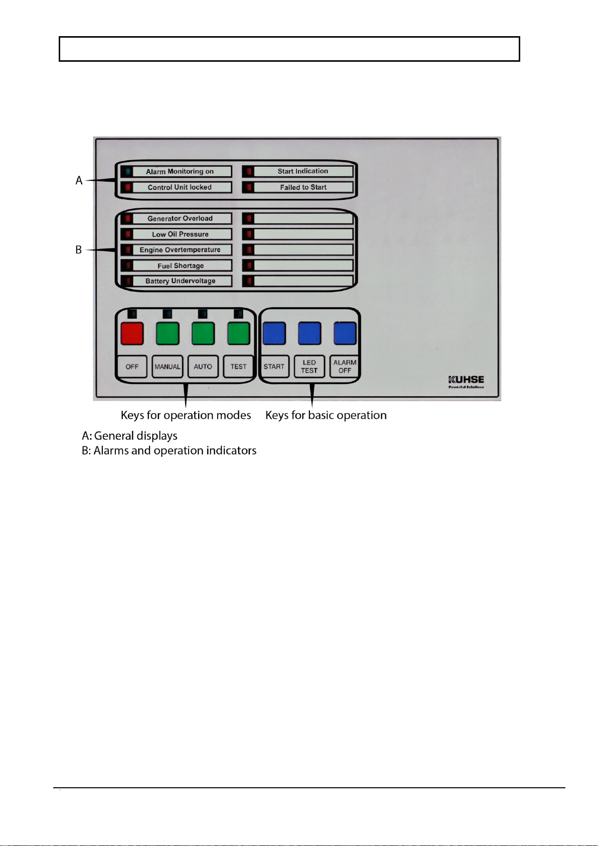
9. Error messages / Programmable operation indicators
Any of the 10 LEDs can either display an error message or be parameterised as an operation indicators.
9.1. Use as an operational indicator
These displays are independent of the selected operating mode. Thus, they can be used as displays of operational con-
ditions via contact inputs as normal signal lamps. The parameterisation is described in the service instructions.
9.2. Use as an error message
The arrival of an error message is displayed by the LED flashing. At the same time, the acoustic signal (for
the entered duration) is controlled. The acoustic signal is switched off with a pulse from the ALARM OFF key
(or automatically after the entered time). However, the LED continues to flash. If the value 0 sec. is entered
for the duration of the horn switch-on, no automatic switch-off is carried out: The horn remains switched on
until manually deleted.
Due to a second button actuation of ALARM OFF, the message switches from flashing to continuously illumi-
nated. Due to the necessary second acknowledgement, e.g. the switching off of the acoustic signal genera-
tor after an automatic switch-off, it can be distinguished which error message has newly occurred.
The display is cleared after the error is eliminated after renewed actuation of the ALARM OFF key.
With messages that lead to the switching-off of the genset, further operation is inhibited and this is indicated
by AUTOMATIC SYSTEM LOCKED. In order to unlock, the OFF operating mode (any actuated external Emergency
OFF buttons must also be unlocked) must be selected.
The parameterisation is described in the service instructions.
9.3. Alarms 9 and 10
Both these alarms can be delayed from 0 to 240 sec. by the signal transmission, i.e. for the alarm contact to
issue an error, the signal must be pending for a parameterised time. Furthermore, both these alarms are also
effective in the Off operating mode (Off), but without switching on the horn. Thus, criteria (e.g. tank overfill-
ing, leakage warning) that always have to be reported can be monitored.