Kuhse KGM - KEA User manual

Alfred Kuhse GmbH
An der Kleinbahn
D-21423 Winsen | Germany
Tel: +49 (0) 4171 798 0
Fax: +49 (0) 4171 798 117
www.kuhse.de
HB-KGM-KEA_DE Version 01
MANUAL
Kuhse Gateway Module
KGM - KEA

Manual
Kuhse Gateway Module
KGM - KEA
HB-KGM-KEA_EN Version 01
Date: 23rd. May 2017
Page 2 of 75
Dear Customer!
Congratulations on your decision to use this product from Alfred Kuhse GmbH in your company.
Note
Due to the continuous further development of our products, there may be minor differences
between the images/text of this documentation and the equipment that it accompanies. We reserve
the right to change designs and the scope of deliveries as well as the right to technical
development and the right to translate the documentation.
Any of the company names and product names mentioned in this manual may be trademarks or
registered trademarks. The citing of third party products is only done for informative purposes and
does not represent an approval or recommendation.

Manual
Kuhse Gateway Module
KGM - KEA
HB-KGM-KEA_EN Version 01
Date: 23rd. May 2017
Page 3 of 75
Table of contents
1Revision history ............................................................................................................5
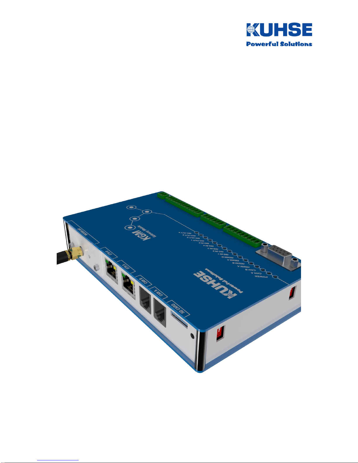
2Introduction...................................................................................................................6
3Safety regulations.........................................................................................................7
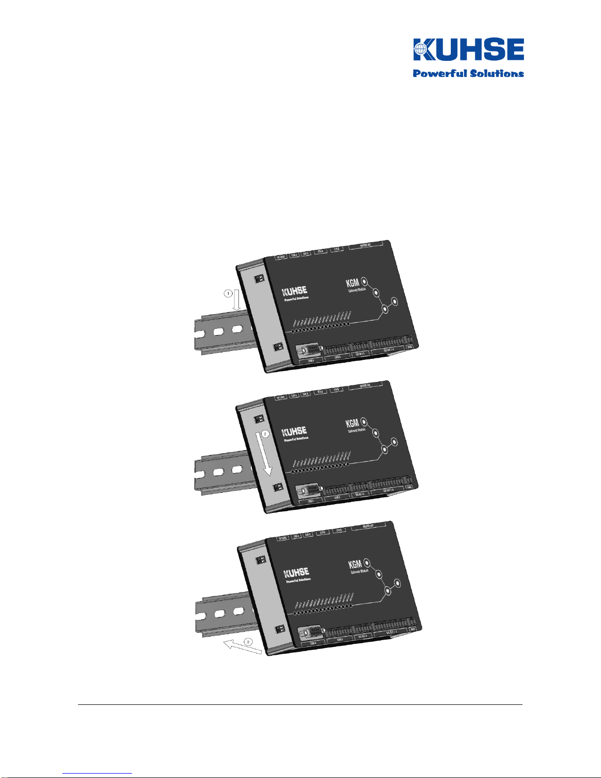
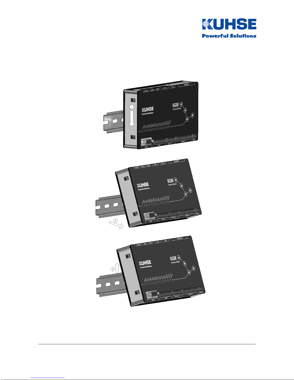
4Mounting and installation..............................................................................................8
5
Inputs and outputs / interfaces....................................................................................10
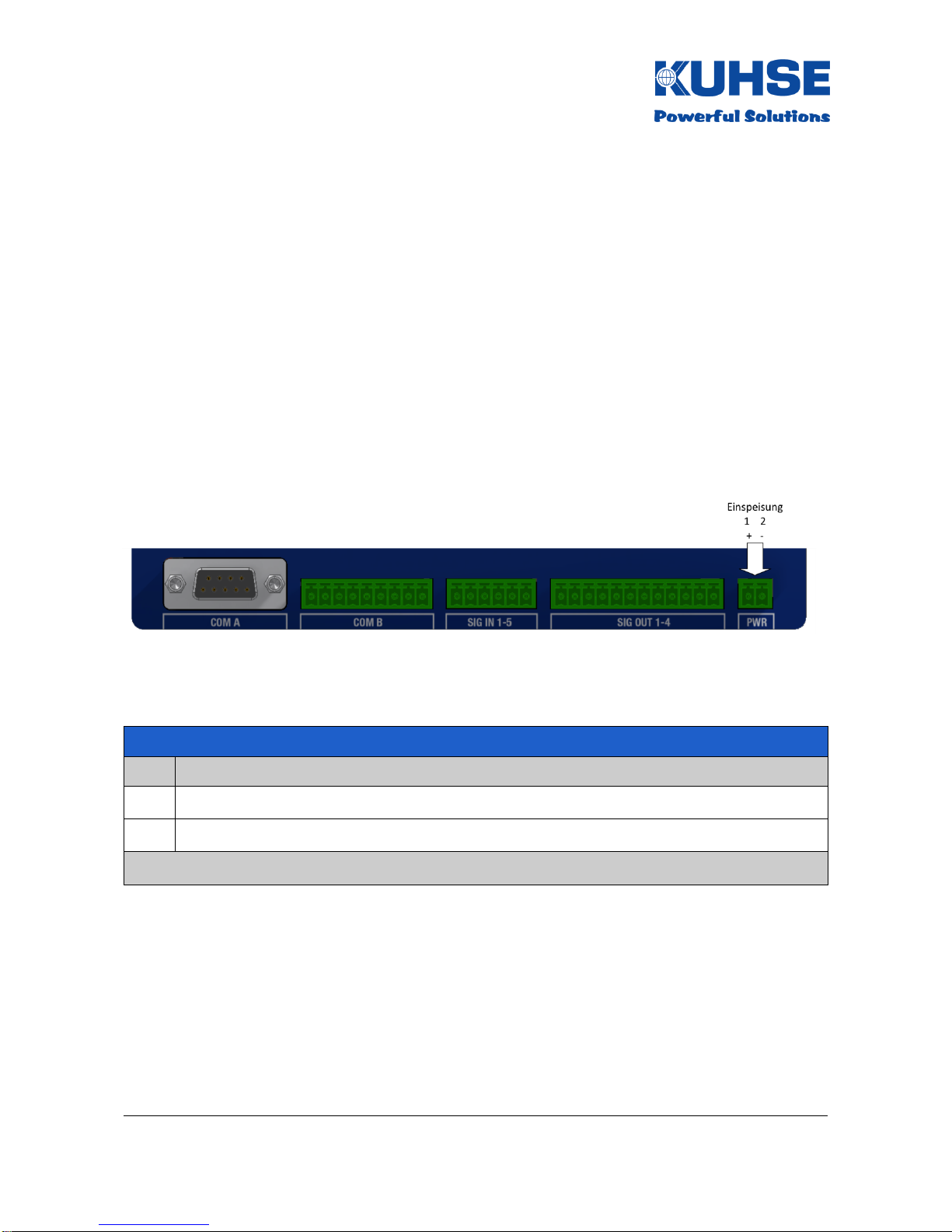
5.1 Power supply..............................................................................................................10
5.2 Relay outputs..............................................................................................................11
5.3 Digital inputs...............................................................................................................12
5.4 Serial interfaces..........................................................................................................13
5.4.1 COM A........................................................................................................................13
5.4.2
COM A - RS232..........................................................................................................13
5.4.3
COM A - RS485..........................................................................................................14
5.4.4 COM B........................................................................................................................15
5.4.5 COM B - RS232..........................................................................................................15
5.4.6 COM B - RS485..........................................................................................................16
5.4.7 RS485 bus termination ...............................................................................................17
5.5 CAN bus.....................................................................................................................18
5.5.1 CAN bus termination...................................................................................................19
5.6Ethernet......................................................................................................................20
5.7 SD card ......................................................................................................................22
5.8 Modem slot.................................................................................................................23
5.9 RESET button.............................................................................................................24
6Commissioning and configuration...............................................................................25
6.1 Boot process...............................................................................................................25
6.2
LED signalling.............................................................................................................26
6.3 Device configuration...................................................................................................27
6.3.1
Device connection and web browser call-up...............................................................27
6.3.2 Log-in .........................................................................................................................28
6.3.3
Start screen - interface configuration ..........................................................................29
6.3.4
Configuration - interfaces............................................................................................30
6.3.5 ModBus configuration.................................................................................................33
6.3.5.1 ModBus RTU Master ..................................................................................................33
6.3.5.2 ModBus RTU Slave ....................................................................................................34
6.3.5.3 ModBus TCP Master ..................................................................................................34
6.3.5.4 ModBus TCP Slave ....................................................................................................35
6.3.6 PROFINET configuration............................................................................................36
6.3.7 KEA configuration.......................................................................................................37
6.3.8
Configuring inputs and outputs ...................................................................................38
6.3.9
KNG configuration ......................................................................................................39
6.3.10
KGM configuration......................................................................................................40
6.3.11 Log-out.......................................................................................................................42
7
Data point list KEA1xx
...............................................................................................43
7.1
Modbus TCP-Slave / RTU-Slave
..............................................................................43
7.1.1
Digital signals KEA1xx
..............................................................................................44
7.1.1.1
Fault messages KEA1xx (FC03)
..............................................................................44
7.1.1.2 Zustandsmeldungen KEA1xx (FC03)..........................................................................45

Manual
Kuhse Gateway Module
KGM - KEA
HB-KGM-KEA_EN Version 01
Date: 23rd. May 2017
Page 4 of 75
7.1.1.3 Analogue values KEA1xx (FC03)................................................................................46
7.1.2
Counter values KEA1xx (FC03)
................................................................................47
7.1.3
Commands to KEA 1xx (FC16)
................................................................................47
7.1.4
Connection status KEA1xx (FC03)
...........................................................................48
7.1.5
Example telegram
.....................................................................................................48
7.1.6
KGM inputs and outputs (FC03 / FC16)......................................................................48
8
Data point list KEA2xx ................................................................................................49
8.1
Modbus TCP Slave / RTU Slave.................................................................................49
8.1.1
Digital signals KEA2xx................................................................................................50
8.1.1.1
Fault messages (FC03) ..............................................................................................50
8.1.1.2 Status messages (FC03)............................................................................................51
8.1.1.3 Analogue values KEA2xx (FC03)................................................................................52
8.1.2
Counter values KEA2xx (FC03)..................................................................................53
8.1.3
Commands to KEA 2xx (FC16)...................................................................................53
8.1.4
Example telegram.......................................................................................................54
8.1.5
KGM inputs and outputs (FC03 / FC16)......................................................................54
8.2
PROFINET .................................................................................................................55
8.2.1
Digital signals KEA2xx................................................................................................56
8.2.1.1
Fault messages ..........................................................................................................56
8.2.1.2 Status messages........................................................................................................57
8.2.1.3 Analogue values KEA2xx............................................................................................58
8.2.2
Counter values KEA2xx..............................................................................................59
8.2.3 Connection status to KEA 2xx.....................................................................................59
8.2.4
Commands to KEA 2xx...............................................................................................59
8.3
PROFIBUS.................................................................................................................60
8.3.1
Digital signals KEA2xx................................................................................................61
8.3.1.1
Fault messages ..........................................................................................................61
8.3.1.2 Status messages........................................................................................................62
8.3.1.3 Analogue values KEA2xx............................................................................................63
8.3.2
Counter values KEA2xx..............................................................................................64
8.3.3 Connection status to KEA 2xx.....................................................................................64
8.3.4
Commands to KEA 2xx...............................................................................................64
8.3.5
KGM inputs and outputs .............................................................................................65
9Firmware update.........................................................................................................66
10 Technical data............................................................................................................71
10.1 Kuhse Gateway Module (KGM - KEA)........................................................................71
10.2 Kuhse Gateway Module - Modem...............................................................................72
10.3 Dimensions.................................................................................................................73
10.3.1 Kuhse Gateway Module (KGM - KEA) ........................................................................73
10.3.2 Kuhse Gateway Module - Modem...............................................................................73
11 RJ12 –CAN bus connection cable..............................................................................74
11.1 RJ12 pin allocation on the KGM..................................................................................74
11.2 CAN bus pin allocation on the KEA.............................................................................74
11.3 Connecting KGM - KEA..............................................................................................74

Manual
Kuhse Gateway Module
KGM - KEA
HB-KGM-KEA_EN Version 01
Date: 23rd. May 2017
Page 5 of 75
1Revision history
Date
Changed
Name
28/10/2016
Creation of the document
C.Behr
18/01/2017
Modbus TCP server data point list added
C.Behr
17/02/2017
Menu point and data point list for PROFINET added
C.Behr
23/02/2017
Data point list for PROFIBUS added
C.Behr
23/02/2017
Data point list KEA1xx for Modbus TCP/RTU added
C.Behr
20/04/2017
Change measure of right view
C.Behr
24/04/2017
Change the pictures of the webserver
C.Behr
22/05/2017
KEA1xx –delete “effective work” from ZLT
C.Behr

Manual
Kuhse Gateway Module
KGM - KEA
HB-KGM-KEA_EN Version 01
Date: 23rd. May 2017
Page 6 of 75
2Introduction
The KGM is a latest-technology, micro-processor controlled device and brings together different
functionalities within a single hardware and software platform.
The device can be used as:
Protocol converter (Gateway) for different communication protocols
Interface converter for connected peripheral devices
Data collection point and router in connection with central and decentralised control rooms
System control and monitoring in energy systems
The device is integrated into an industrial housing. It has a wide input voltage range of 9-36VDC
for the internal power supply. All inputs and outputs are isolated. Alongside numerous
communications interfaces, the device also has additional digital inputs and relay signalling
outputs. Furthermore, a GSM/UMTS/LTE modem can also be installed in a device insertion slot for
communication via a mobile telephony network. Additional modules can be connected via CAN bus
to allow expansion with additional digital inputs, analogue measurements and relay signalling
outputs. All inputs and outputs are implemented via plug-in connectors.
The following interfaces are available in the device:
Power supply input: 9-36VDC (isolated)
2x Ethernet 10/100/1000Mbit
2x RS232
2x RS485
2x CAN bus
1x SD card
5x Digital input
4x Relay output
1x Radio modem slot

Manual
Kuhse Gateway Module
KGM - KEA
HB-KGM-KEA_EN Version 01
Date: 23rd. May 2017
Page 7 of 75
3Safety regulations
These installation instructions and operating instructions contain all important information for
installing, configuring and commissioning the product. Please read through the document carefully
and ensure that it is available to all personnel who remove the product from the packaging,
connect it, configure it and commission it.
Please note: The product shall be unpacked, installed and
commissioned only by authorised specialist personnel. In the event of
improper handling, erroneous wiring of connections or improper use
in general, this can result in the failure of the product.
The manufacturer accepts no warranty or guarantee claims for damage resulting from improper
use of the product or erroneous wiring.
Please note: The product shall not be used with the housing open. In
this case the product can be permanently damaged through contact
with conductor tracks and electronic components. In addition, all
warranty or guarantee claims shall be void in the event that the
housing has been opened without the knowledge of the manufacturer.
This product contains sensitive electronic components. Please only remove the product from its
packaging immediately before its integration into an energy system. Please follow the rules for
good ESD practice during the installation and commissioning of electronic products. Please avoid
any impermissibly high mechanical stresses on the device. An unprotected installation in
environments that do not represent the technical operating conditions, is not permitted. Use in
outdoor areas and humid rooms is forbidden. Please protect the product from direct or indirect
moisture.
Please note: Please use the input and output connectors provided
with the product exclusively. Please follow the recommendations for
minimum cable cross-sections for the specified connections.
Defective devices should be immediately removed from operation and submitted for fault analysis
along with a written description of the fault that occurred.

Manual
Kuhse Gateway Module
KGM - KEA
HB-KGM-KEA_EN Version 01
Date: 23rd. May 2017
Page 8 of 75
4Mounting and installation
The mechanical installation of the product is very simple. The device is equipped with a rear panel
adapter for DIN rail mounting (NS 35mm). It can be installed on DIN rails with a height of 7.5 and
15mm.
Remove the device from the packaging. Hold the device at a slight angle and hang it into the DIN
rails from above (1). Guide it downwards (2) with light pressure and move the underside of the
device towards the DIN rail (3). Once the device is parallel to the DIN rail, you can release the
device. It now latches onto the underside of the DIN rail automatically.

Manual
Kuhse Gateway Module
KGM - KEA
HB-KGM-KEA_EN Version 01
Date: 23rd. May 2017
Page 9 of 75
If a device is to be removed, first press it downwards (1) and then after that the underside must be
tilted forwards (2). The device is now hanging only from the top edge of the DIN rail and can be
removed from there (3).

Manual
Kuhse Gateway Module
KGM - KEA
HB-KGM-KEA_EN Version 01
Date: 23rd. May 2017
Page 10 of 75
5
Inputs and outputs / interfaces
5.1 Power supply
The power supply for the device can be implemented directly from a DC source (e.g. batteries), an
external DC/DC converter or an external AC/DC converter (mains adapter).
The positive pole of the input is protected internally with a current-limiting polyfuse. The input is
also protected against reverse polarity connection with a diode. However, the internal device
protection does not replace the cable protection required for the supply line (important with direct
battery connection) and for the external mains adapter.
The input is protected against short-term voltage spikes. However, continuous application of
excessive voltage can result in the internal protection heating up severely and to the device failing.
For this reason, the permissible input voltage range (see "Technical data") must always be
complied with!
If the power supply has been correctly connected and switched on, the internal auxiliary power
supply of the device is activated. The correct condition is indicated with the green
"Power" LED on the front face. The internal power supply is isolated from the supply feed.
The supply feed is implemented with a two-pole plug-in connector and identified with "PWR".
"PWR" power supply (isolated, 9-36 V DC / 1 A)
Pin
Function
1
DC voltage (+)
2
DC voltage (-/GND)
Connector MC 1.5/2-ST-3.5; Phoenix Contact 1840366; min. 2 x 0.75mm2

Manual
Kuhse Gateway Module
KGM - KEA
HB-KGM-KEA_EN Version 01
Date: 23rd. May 2017
Page 11 of 75
5.2 Relay outputs
4 controllable relay outputs are integrated into the device for potential-free signalling of alarm
messages and for controlling external devices and modules.
The relay outputs are wired as changeover contacts (COM, NC, NO) to the external connection.
"SIG OUT 1-4" connector - relay outputs (isolated, 30 V / 1 A max.)
Pin
Function
1
Relay 1 - NC
2
Relay 1 - COM
3
Relay 1 - NO
4
Relay 2 - NC
5
Relay 2 - COM
6
Relay 2 - NO
7
Relay 3 - NC
8
Relay 3 - COM
9
Relay 3 - NO
10
Relay 4 - NC
11
Relay 4 - COM
12
Relay 4 - NO
Connector MC 1.5/12-ST-3.5; Phoenix Contact 1840463; min. 12 x 0.5mm2
In relaxed condition (relay coil not energised) the COM and NC contacts are closed.
In activated condition (relay coil energised) the COM and NO contacts are closed. In addition, this
active condition is indicated separately with a green LED for each relay output (SIG OUT 1-4).
A delay time for the relay reporting can be set in the configuration interface.

Manual
Kuhse Gateway Module
KGM - KEA
HB-KGM-KEA_EN Version 01
Date: 23rd. May 2017
Page 12 of 75
5.3 Digital inputs
5 digital inputs are integrated into the device for the polling of external signal reporting loops.
The inputs use a common signal voltage of 5V. The signal voltage as well as the inputs themselves
are internally isolated.
Only potential-free signal loops are permitted to be connected. The minimum contact conductance
of the signalling circuits (auxiliary switches, relays, contactors, etc.) connected must not drop below
10 mA.
"SIG IN 1-5" connector - digital inputs (isolated, 5 V / 10 mA)
Pin
Function
1
Digital input 1
2
Digital input 2
3
Digital input 3
4
Digital input 4
5
Digital input 5
6
Signal voltage +5V DC
Connector MC 1.5/6-ST-3.5; Phoenix Contact 1840405; min. 6 x 0.5mm2
In closed condition, that means that if the 5V supply voltage is present at the respective digital
input, an internal reporting signal is generated. In addition, this active condition is indicated
separately with a green LED for each digital input (SIG IN 1-5).

Manual
Kuhse Gateway Module
KGM - KEA
HB-KGM-KEA_EN Version 01
Date: 23rd. May 2017
Page 13 of 75
5.4 Serial interfaces
The RS232 and RS485 serial interfaces are each available via identical plug-in connectors.
However, the connector pins are not double-assigned, i.e. it is possible to use the respective
interfaces simultaneously on one connector.
5.4.1 COM A
Devices that communicate via the RS232 or RS485 (half-duplex) interfaces can be connected to
serial port A. The interfaces are isolated.
5.4.2
COM A - RS232
Connector "COM A" - Serial interface RS232
Pin
Function
1
RS232 A - RXD
2
RS232 A - TXD
4
RS232 A - RTS
7
RS232 A - CTS
9
RS232 A - GND
3,5,6,8
RS232 A - CTS
Connector Sub-D9; male, 5 x 0.25mm2
The following parameters can be configured for the serial interface COM A - RS232 A:
Activate/deactivate interface
Baud rate, data bits, parity, stop bits, sequence control
If the interface is active, the green "RS232 A" LED illuminates.

Manual
Kuhse Gateway Module
KGM - KEA
HB-KGM-KEA_EN Version 01
Date: 23rd. May 2017
Page 14 of 75
5.4.3
COM A - RS485
Connector "COM A" - Serial interface RS485
Pin
Function
3
RS485 A - B
5
GND ISO (only for external termination)
6
5 V ISO (only for external termination)
8
RS485 A - A
1,2,4,7,9
Not relevant
Connector Sub-D9; male, 3 x 0.25mm2
The following parameters can be configured for the serial interface COM A - RS485 A:
Activate/deactivate interface
Baud rate, data bits, parity, stop bits
If the interface is active, the green "RS485 A" LED illuminates.

Manual
Kuhse Gateway Module
KGM - KEA
HB-KGM-KEA_EN Version 01
Date: 23rd. May 2017
Page 15 of 75
5.4.4 COM B
Devices that communicate via the RS232 or RS485 (half-duplex) interfaces can be connected to
serial port B. The interfaces are isolated.
5.4.5 COM B - RS232
Connector "COM B" - Serial interface RS232
Pin
Function
1
RS232 B - GND
2
RS232 B - CTS
3
RS232 B - TXD
4
RS232 B - RTS
5
RS232 B - RXD
6,7,8,9
Not relevant
Connector MC 1.5/9-ST-3.5; Phoenix Contact 1840434, 5 x 0.25mm2
The following parameters can be configured for the serial interface COM B - RS232 B:
Activate/deactivate interface
Baud rate, data bits, parity, stop bits, sequence control
If the interface is active, the green "RS232 B" LED illuminates.

Manual
Kuhse Gateway Module
KGM - KEA
HB-KGM-KEA_EN Version 01
Date: 23rd. May 2017
Page 16 of 75
5.4.6 COM B - RS485
Connector "COM B" - Serial interface RS485
Pin
Function
1-6
Not relevant
7
RS485 B - B
8
RS485 B - A
9
Termination RS485 B
Connector MC 1.5/9-ST-3.5; Phoenix Contact 1840434, 3 x 0.5mm2
If bus termination is required, pin 7 must be externally linked to pin 9. Resistance circuitry is
already installed in the device.
The following parameters can be configured for the serial interface COM B - RS485 B:
Activate/deactivate interface
Baud rate, data bits, parity, stop bits
If the interface is active, the green "RS485 B" LED illuminates.

Manual
Kuhse Gateway Module
KGM - KEA
HB-KGM-KEA_EN Version 01
Date: 23rd. May 2017
Page 17 of 75
5.4.7 RS485 bus termination
For correct operation of the RS485 bus, it is necessary to fit a termination resistor at both ends of
the bus. If the device is installed at the end of the bus, an internal termination resistor can be
activated via DIP switch. This simplifies the installation as there is no need to wire an external
resistor. If a PROFIBUS connector with integrated termination is used, the internal termination
should be deactivated on the DIP switch!
There must always be two termination resistors (each 220 Ohm)
installed in an RS485 bus. However, there must never be more
than two resistors active. If the device is installed in the middle
of a system configuration and external resistors are active at
both extremities of the bus, the internal resistor must be
deactivated. If the termination is incorrect, the RS485 bus
communication may be occasionally disrupted or the RS485 bus
may fail completely.
The 3-pole DIP switch for the RS485 bus termination is located at the left, bottom side of the
device.
RS485 bus termination
DIP switch
Function
1-3
ON = RS485 A termination active; OFF = RS485 A termination deactivated

Manual
Kuhse Gateway Module
KGM - KEA
HB-KGM-KEA_EN Version 01
Date: 23rd. May 2017
Page 18 of 75
5.5 CAN bus
The device has 2 CAN bus interfaces that operate independently of one another. The interfaces
are isolated. The interfaces can be operated with CAN protocol 1.0A or 1.0B (proprietary). In doing
so, each interface can have its own protocol and its own baud rate.
Connector "COM A" - CAN bus A (isolated)
Pin
Function
1.2
Not relevant
3
CAN - high
4
CAN - low
5.6
GND
Connector RJ12 6p/6c, 6 x 0.5mm2
Connector "B" - CAN bus B (isolated)
Pin
Function
1.2
Not relevant
3
CAN - high
4
CAN - low
5.6
GND
Connector RJ12 6p/6c, 6 x 0.5mm2
The respective CAN protocol and the CAN bus data rate can be selected or configured.

Manual
Kuhse Gateway Module
KGM - KEA
HB-KGM-KEA_EN Version 01
Date: 23rd. May 2017
Page 19 of 75
5.5.1 CAN bus termination
For correct operation of the CAN bus, it is necessary to fit a termination resistor at both ends of
the bus. If the device is installed at the end of the bus, an internal termination resistor can be
activated via DIP switch. This simplifies the installation as there is no need to wire an external
resistor.
There must always be two termination resistors (each 120 Ohm)
installed in a CAN bus. However, there must never be more than
two resistors active. If the device is installed in the middle of a
CAN configuration and external resistors are active at both
extremities of the bus, the internal resistor must be deactivated.
If the termination is incorrect, the CAN bus communication may
be occasionally disrupted or the CAN bus may fail completely.
The DIP switch for the CAN termination is located at the left, top side of the device.
CAN bus termination
DIP switch
Function
1
ON = CAN A termination active; OFF = CAN A termination deactivated
2
ON = CAN B termination active; OFF = CAN B termination deactivated

Manual
Kuhse Gateway Module
KGM - KEA
HB-KGM-KEA_EN Version 01
Date: 23rd. May 2017
Page 20 of 75
5.6 Ethernet
The device has 2 Ethernet ports that operate independently of one another with separate physical
MAC addresses and their own IP address space. The interfaces are isolated.
Two LEDs on the respective port indicate an existing link (green, steadily illuminated LED) and
active communication "Traffic" (yellow, flashing LED).
Connector "ETH A" - Ethernet Port A
Pin
Function
1
TRP0+
2
TRN0-
3
TRP1+
4
TRP2+
5
TRN2-
6
TRN1-
7
TRP3+
8
TRN3-
Connector RJ45 8p/8c, 8 x 0.5mm2 (Standard CAT 5)
Table of contents
Popular Gateway manuals by other brands

Cisco
Cisco VG248 - Gateway Hardware installation guide

IOGear
IOGear GCN1000 PCPortal installation guide

Juniper
Juniper SRX 1400 SERVICES GATEWAY - Hardware guide

TELES
TELES ECOTEL manual

ZyXEL Communications
ZyXEL Communications AMG1302-T series user guide

DISCOVER
DISCOVER Lynk Lite Installation and operation manual