Kuller KPG22-2 User manual

GASOLINE GENERATORSET
USER SMANUAL

Foreword
Thankyouforpurchasing ourgasolinegeneratorandhopethatyouwill enjoyoperatingyourunit,
oneofthefinestmodelsinthemarket.
ThisManualprovidesinformationregardingthesafeoperationandmaintenance ofthisproduct.It
isapplicableforModelsno.KPG22-2/KPG22/KPG28/KPG30/KPG42/KPG55/KPG80Egasoline
generators. Thismanualshouldbeconsideredapermanentpartoftheunitandshouldremainwith
theproductifitisresold.
Everyefforthasbeenmadetoensuretheaccuracyoftheinformationinthismanual.Wereservethe
righttochangethisproductandspecificationsatanytimewithoutpriornotice.
Important Message
Thismanualcontainsspecialmessagestobringattentiontopotentialsafetyconcerns,generator
damageaswellashelpfuloperatingandservicinginformation.Pleasereadalltheinformation
carefullytoavoidinjuryandmachinedamage.
Payspecialattentiontostatementswiththefollowingsymbolsandwords.
WARNING indicatesahazard,ifinstructionsarenotstrictlyfollowed,canresultinhuman
injuryordeath.
CAUTION indicatesahazard,ifinstructionsarenotstrictlyfollowed,couldresultinhuman
injuryand/orpropertydamage.
NOTE usestogivehelpfulinformation.

2
TABLEOFCONTENTS
Foreword ...1
TableofContents ....2
1. SafetyInstructions .3
2. IntroductiontoPartsand Components ..5
3. Pre-operationCheck/Inspection 6
3.1EngineOilLevel 6
3.2FuelLevel ..7
3.3AirCleaner .8
3.4Battery 8
3.5GroundingtheUnit .....8
4. StartingtheEngine 9
5. UseoftheGeneratorSet ... ...10
5.1 Grounding ...10
5.2 WattageofElectricalDevices ..10
5.3 ConnectingSequence 10
5.4 ConnectingMethod .11
5.5 InstructionsonAC Usage 11
5.6 InstructiononDCUsage .12
6StoppingtheEngine 13
7Maintenance 14
7.1 Maintenance Schedule 14
7.2 ReplacementofEngineOil .14
7.3 Maintenance ofSparkPlug .15
7.4 Maintenance ofFuelFilterCup ...15
8ElectricalStart ..16
9Storageand Transportation. .17
10 Troubleshooting ...18
11 Specifications 19

3
1. SafetyInstructions
CAUTION Read themanualcarefully.Donotoperatetheequipmentuntilyouhave read the
manualandfamiliarizedyourselfwiththesafety,assembly,operation,and
maintenance instructions.
CAUTION Thisequipmentshouldonlybeoperatedonastable, levelsurface.
CAUTION Don toverload theunit, oritsservice lifewill beshortened.
CAUTION Don toperateorstoretheunit inhumidplacesand/oronmetalsurfaces.
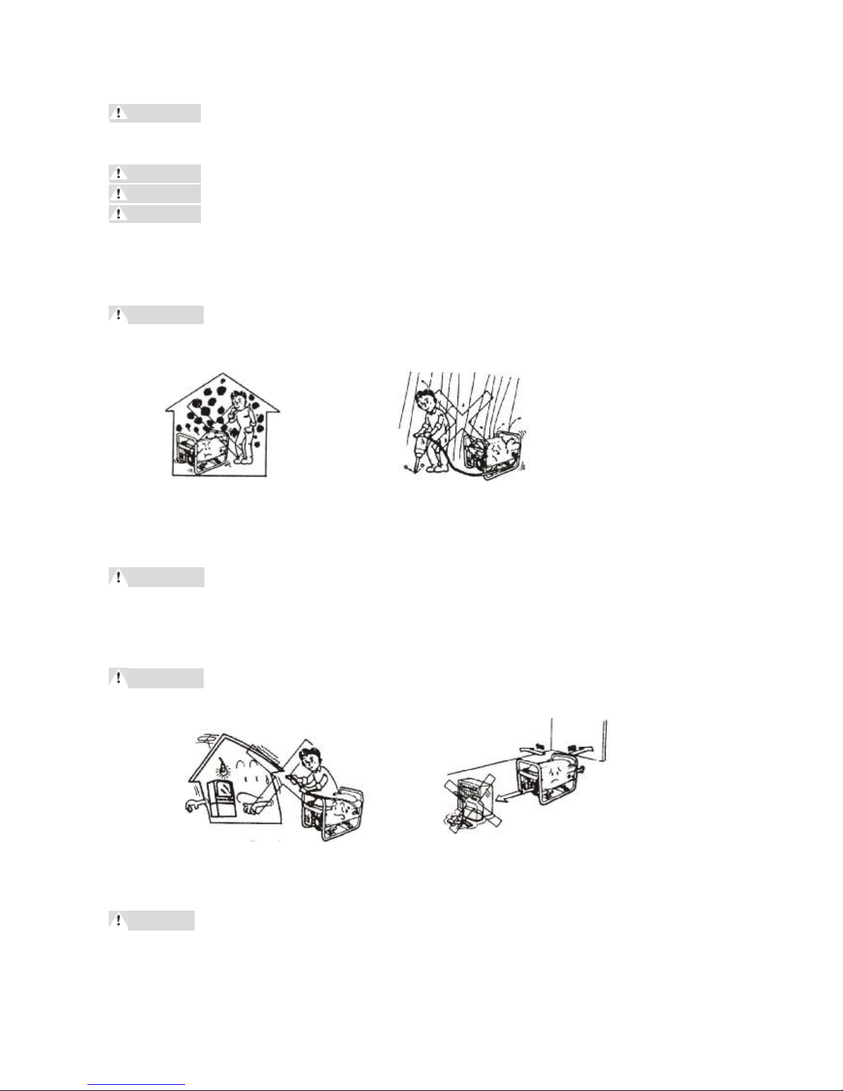
Don’toperatetheunitinenclosedorpartiallyenclosedplaces,suchasrooms,basements,
garages, caves, tunnels, etc (Figure1)
WARNINGDANGER:CarbonMonoxide. Using ageneratorindoors(orenclosedorpartially
enclosedplaceswithoutgoodventilation)CAN KILLYOU INMINUTES.
GeneratorexhaustcontainsCarbonMonoxide, acolorless, odorless, butdeadlygas.
Figure1 Figure2
Don’toperatetheunitunderwetcircumstances (Figure2)
WARNING DANGER:ElectricShock.Thegeneratorproducespowerfulvoltage,operationin
wetcircumstancescanresultinelectrocution.
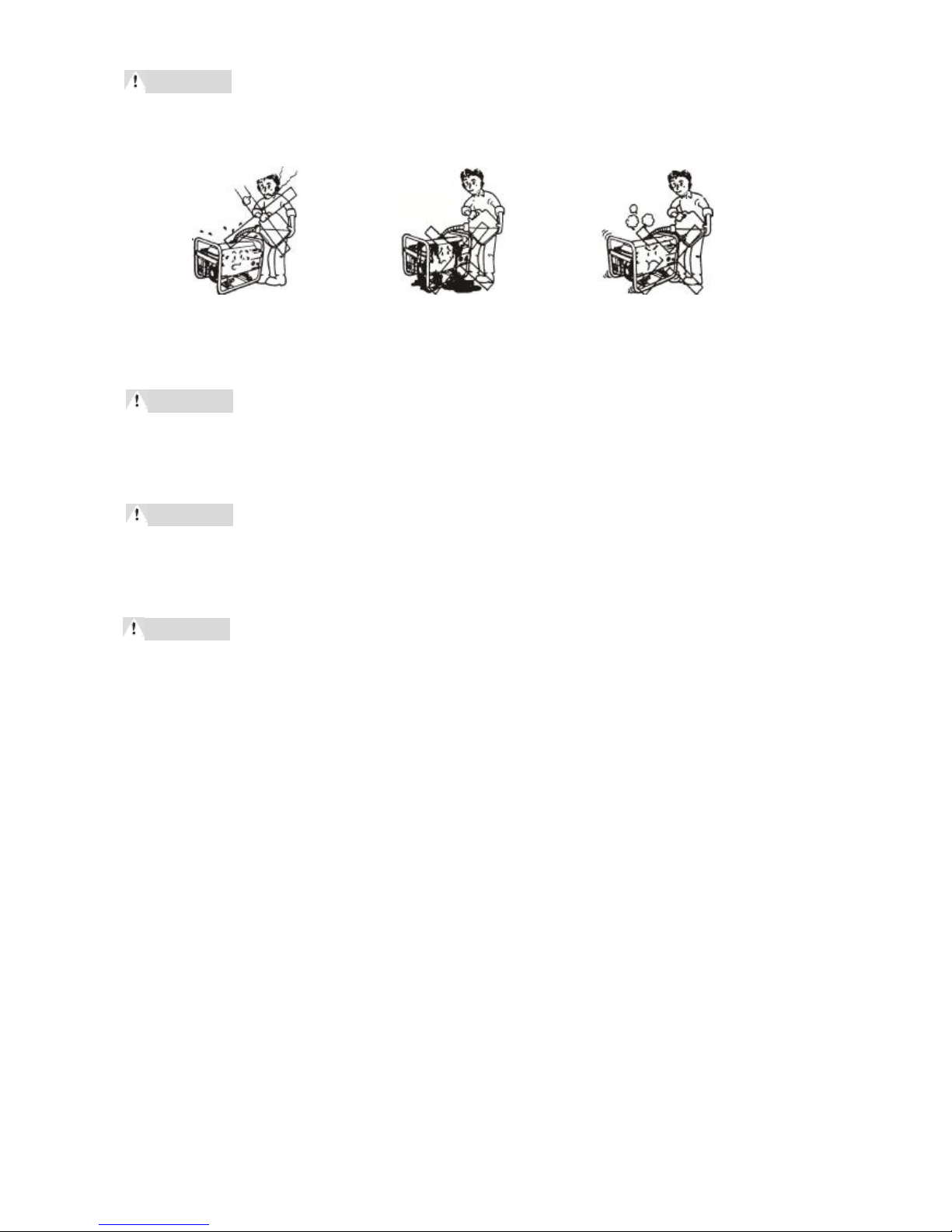
Don’tconnecttheunittobuildingcircuit (Figure3)
WARNINGDANGER:Fireand EquipmentDamage. Improperconnectionmayresultin
generatordamageorafire.
Figure3 Figure4
Keepinflammablesatleast1meteraway fromtheunit (Figure4)
WARNINGDANGER:Fireand/orExplosion. Thegeneratorsetproducesheatwhenitis
working.Operationnearinflammablescancausetheinflammablesover-heatedand
thuscauseafire.
Prohibittosmokeduringfuelfilling (Figure5)

4
WARNINGDANGER:Fireand/orExplosion. Gasolineanditsvaporsarehighlyflammable
andexplosiveundercertainconditions.Gasolineanditsvaporcaneasilybeignited
bycigaretteends, aswellassparks, openflames, hotsurfaces, etctoresultinfireor
explosion.
Figure5 Figure6Figure7
Takecaretoavoidfuelspillagewhenfilling. (Figure6)
WARNINGDANGER:Fireand/orExplosion. Gasolinespillageanditsvaporsarehighly
flammableandexplosiveundercertainconditions.
Beawaretofillfuelafterstoppingtheengine. (Figure7)
WARNINGDANGER:Fireand/orExplosion. Gasolineanditsvaporsarehighlyflammable
andexplosiveundercertainconditions.
Beawareofhotsurfaces.
WARNINGDanger:Burns. Themufflerisveryhotduringand/orimmediateafterengine
operation.Accidentalcontactwithhotsurfacessuchasthemufflerwillresultin
seriousburns.
1.9Keepchildrenand otherpeopleaway fromtheunitduringoperation.

5
2. IntroductiontoPartsand Components
Mainpartsandcomponents oftheunitareillustratedasfollows:
Figure8
1. FuelGauge2. FuelTankCover3.ACPlug Socket
4. CircuitBreaker5.Voltmeter6. Dipstick
7. IgnitionSwitch8. DrainPlug 9. RecoilStarter
10. FuelSwitch11.AirCleaner12. ChokeLever
13. GroundTerminal14. Muffler15. SparkPlug
Note:Picturesanddrawingsusedinthismanualareforreference onlyanddonotrepresentany
specificmodel.

6
3. Pre-operationCheck
Pleasedothefollowing preparationbeforeoperationtoensurethereliablefunctionoftheunit,orit
mayresultinequipmentdamageandservice lifeabridgement.
EngineOilLevel
Littleengineoilisfilledintheenginewhenyoupurchasetheunit.Beforeoperatingtheunit,
pleasefillinadequateamountofengineoilofthepropertype.
Theoilcapacityofthemachineis0.45 Lfor1200 and1300,0.6Lfor2500(E) 、3000(E)and
3200(E), and1.1Lfor3500(E)up to7500(E).
SAE10W-30 engineoilisrecommendedforgeneral,
all-temperatureusage. Otherviscositiesoil(asshown
inthechart)maybeusedwhentheaverage
temperatureinyourarea iswithintheindicatedrange.
NOTE:Dothecheckonlywhentheunitstops operationonalevelground.
Takeouttheoilfillercoverandhavethedipstickcleaned(Figure9)
Figure9 Figure10
Insertthedipstickintotheoilfillerholewithoutscrewingitin(Figure10)
Iftheoil levelisbelowthelowermarkofthedipstick,
add oiltoitshighermark(Figure11)
Re-screwintheoilfillercover/dipstickandfastenitsecurely(Figure12)
FuelLevel
Toensurethesmoothperformance oftheunit,fresh,unleadedgasoline90# orhigheris
recommendedtobeaddedintotheenginebythefollowing steps.
Puttheunitonalevelsurface.
Removethefuelfillercover(Figure13)
SurroundingTemperature

7
Checkthefuellevel,andadd fuelifnecessary.Besurenottoaddtoo full.Fuelcapacityfor
themachine:3L(1200),6L(1300),15L(2500[E],3000[E],3200[E]),and25L(3500[E]up to
7500[E])(Figure14)
CAUTION Thefuelexpansioninthetankcanresult infuelspillageandpossiblefireorexplosion.
Pleasedon tadd fueltotheceilingofthetanktoleaveroomforfuelexpansion.
Fill fueltotheshoulderofthefuelfilter/Strainer.(Figure15)
Re-mountthefuelfillercoverandtightenitwell(Figure16)
CAUTIONDon’taddamixtureofgasolineand engineoilusedfor2-strokepetrolengines.
Don’tusestalefuel.
Avoidforeignmattersgettingintothetank, suchasdusts, wateretc.
Drainfuelinthetankand carburetoriftheunitisnottobeusedforlongtime
asfueldegenerationowingtolong-timestoragemay causeitdifficulttostart
theengine.
AirCleaner
Removetheaircleanerhousing(Figure17)
Checkittosee iftheaircleanercoreisintactand/orclean.Ifitisbroken,haveitreplaced
withanewone.
Ifthecoreisdirty, haveitcleanedinthefollowingway. (Figure18)
a) Cleanthecoreincleansing solvent

8
b) Dryitup
c) Dipafewdrops ofengineoilonit
d) Squeeze outexcessoil
Putthefilterelementbacktoitsoriginalplace,mountthecover and
fastenitsecurely(Figure19)
3.4Battery(ForElectricalStartModelsonly)
3.4.1Checkthebatteryandconnectingports.
3.4.2Checkeachcellofthebatterytosee iftheelectrolytelevelofthebatteryisbetweentheupper
andlowerlevelmarkedonthebattery. (Figure20)
1. UpperLevel
2. LowerLevel
3.4.3Checkthespecificgravityofelectrolyte
3.5GroundingtheUnit
Keepthegeneratorproperlygroundedtoavoidelectrocution.
(Figure27)
Thereisagroundingnutonthelowerrightofthecontrol
panel.Connectthenutandtheearthfirmlywithawire
beforeoperation.
WARNING DANGER:ElectricalShock.Failuretoproperlygroundthegeneratorcanresult
inelectrocution.

9
4. StartingtheEngine
NOTE Beforestartingtheenginebesurethatallthepre-operationcheckhasbeendone.
Unplug all ACsockets todisconnectloads
Checkiftheunithasbeenproperlygrounded.
Checkthelevelofengineoil andfuel.
SetthefuelswitchtoONposition(Figure22)
SettheChokeLevertoOFF position(Figure23)
NOTE Don tclosethechokewhentheengineishot.
SettheIgnitionSwitchtoON positionforhandstartmodels;Turnthekey-switchtoON
positionforE-startunits(Figure24)
Pull up theStartingHandlegentlyuntil resistance isfelt,thenpullitup rapidly.Putbackthe
handleslowlytoavoiddamagetothestartingsystem.Turnthekey-switchtoSTARTpositionfor
E-startModels, fordetailspleaseconsultChapter8.(Figure25)
Iftheenginefailstostart,pleaseturnonthechokeleverandrepeatwhatyoudo inSection4.6.
WARNING Aftertheenginestarted,releasethestartinghandlegentlytoavoidpersonalinjury
and/orequipmentdamageduetothebouncingback.
Once theengineisstarted,setthechokelevertoON position. (Figure
26)

10
5. Useofthe GeneratorSet
Constantlydothefollowing tokeeptheunitinsound,
workablecondition.
WARNING DANGER:ElectricalShock.Failureto
properlygroundthegeneratorcanresultin
electrocution.
5.1Grounding
Keepthegeneratorproperlygroundedtoavoidelectrocution.
(Figure27)
5.2WattageofElectricalDevices
Referencedataoftheratingwattageand(thewaytocalculate)thestartingwattageoftheelectric
appliancesconnectingtothegenerator.
Description Wattage Species Examples
Start Rating ElectricDevices Start Rating
IncandescentLamp
Heating Devices X1 X1
Incandescent
Lamp
TV
IncandescentLamp
100W
100VA
(W)
100VA
(W)
FluorescentLamp X2 X1.5
Fluorescent
Lamp
FluorescentLamp
40W 80VA(W) 60VA(W)
DriveDevice X3-5 X2
Refrigerator
ElectricFan
Refrigerator
150W
450---750
VA(W)
300VA
(W)
Table5.1
WARNING Electricmotorsrequirefarmorewattagethantheratedonesatstarting,besurenot
toexceedtheratedoutputofthegeneratorsetwhenconnectingloadstoit.
5.3ConnectingSequence
Iftherearetwoormoreloadsneeding powersupplyfromthegenerator,besuretoconnectthem
onebyonewiththeoneofhigheststartcurrentfirst,followedbythe2nd highest,until thelowest.
(Figure28)

11
5.4ConnectingMethod
Illustrationofconnectingmethods(Figure29)
WARNINGDANGER: GeneratorDamageand/orFire.Whenitisneededtoconnectthe
generatortobuilding powersupply,besuretohaveaskilledelectriciantodothejob.
Improperconnectionbetweenthegeneratorandloadsmayresultingeneratordamage,
evenafire.
5.5InstructionsonAC Usage
NOTE AcquaintyourselfwiththeparametersontheControlPaneltoensurecorrectusage
withintheratedoutputofthegeneratorset.
CAUTIONThegeneratorsetcanworkatitsratedoutputonlyunderconstanttemperature,
pressureand humidity.Thevariationoftemperature,pressureand humiditymay
influence theoutputofthegenerator.
Thetemperaturerangeinwhichtheunitcanbestartedis150C-400C.Thestandard
conditionis
--Surroundingtemperature:250C
--SurroundingPressure:100kPa
--RelevantHumidity:30%
--HeightaboveSeaLevel:1000m
5.5.1Startthegenerator(Figure30)

12
5.5.2Connectthedevices(Figure31)
5.6InstructiononDCUsage
PayspecialattentiontotheconnectionofpositiveandnegativepolesinDCapplication.
CAUTION TheDCoutputshouldnotbeusedaspowersupplyforbatterycharging.

13
6StoppingtheEngine
6.1ForEmergency:SettheignitionswitchtoOFF positiondirectlytostopthegenerator.
6.2UnderNormalCondition
6.2.1Turnoff theACbreakerandunplug alltheloads(Figure34)
6.2.2Runtheunitforseveralminuteswithoutloadtocooldownthegeneratorset.
6.2.3SettheignitionswitchtoOFF position(Figure35)
6.2.4SetthefuelswitchtoOFF position(Figure36)
WARNING Don ttouchtheheatingcomponentsbeforetheunitcoolsdownafterstoppingthe
enginetoavoidburns.
CAUTION Fuelstorageinunitwhichisnottobeusedforlongtimewillcauseitdifficultto
starttheengine. Drainthefuelforlong-timestorageoftheunit.

14
7Maintenance
7.1Maintenance Schedule: TheUnitshouldbeservicedaccordingtothefollowing Maintenance
Schedule:
Period
Item
Each
Time
20 Hrsor
1stMonth
50HrsorEvery
3 Month
100Hrsorevery6
Month
300Hrsoreveryone
year
Checkengineoil Check
Replace engineoil Replace Replace
Checkaircleaner Check
Washaircleaner Clean
Oil filtercover Clean
Batteryelectrolyte
level Check
Sparkplug Clean
Valveclearance Check&readjust
Washcylinder
cover Clean
Washfueltank Replace every3 years
Battery Replace ifnecessary
WARNINGDon’tcarryoutanymaintenancewhentheunitisworking.
7.2ReplacementofEngineOil
Pleasedrainthoroughlytheengineoil beforetheenginecompletelycooleddowntoguarantee the
adequateoilfluidity.
7.2.1Unscrewandtakeoutthedipstick(Figure37)
7.2.2Unscrewthedrainplug, anddrainengineoilfromthecrankcase.
7.2.3Putthedrainplug back(Figure38)
7.2.4Fillengineoiltotheupperlevelofthedipstick.
EngineOilrecommended:4-strokegasolineengineoil----engineoil class SE, SFfromAPI
Service ClassificationorSEA10W-30 engineoil equivalenttoClass SG.
7.2.5Re-mountthedipsticktoits originalposition.
CAUTIONPleaseputdiscardoilintospecifiedcontainer. Don’tpouritonearth.

15
7.3Maintenance ofSparkPlug
Pleasedothejobwithaspecialtool
7.3.1Disconnectthesparkplug capandthespark
plug, clearthedirtaroundthesparkplug (Figure39)
7.3.2Removethesparkplug withaspecialtool
(Figure40)
7.3.3Checkthesparkplug,iftheinsulatorisbroken,
havethesparkplug replaced.Doawaywithcarbonfouling aroundthesparkplug withametal
brush. (Figure41)
7.3.4Checkthesparkplug clearancetosee ifitisbetween0.7-0.8mm,adjustitifnecessary(Figure
42)
7.3.5Re-mountthesparkplug anditscap. (Figure43)
SparkPlugrecommended:F7TC
NOTE Screwinhalfroundmoreafterthesparkplug compressesits
washerifanewsparkplug isused.Screwinone-fourth
roundmoreonlyifthe oldoneisused.
CAUTIONThesparkplugmustbetightenedsecurely,oritmay resultinmachinedamage
owingtoover-heating.
CAUTIONPleasebecarefultochoosetheheatvalueofthesparkplug.Pleaseadoptspark
plugofrecommendedorequivalentmodeland type
7.4Maintenance ofFuelFilterCup
7.4.1SetthefuelswitchtoOFF position,Dismantlethefuelfiltercup andgauze
(Figure44)
7.4.2Cleanthefuelfiltercup andgauze.
7.4.3Mountthefuelfiltercup andgauze totheiroriginalposition.
(Figure45)

16
8.ElectricalStart
WARNING Poisonousliquidsulfuricacidinsidebattery.Tilting generatorsetwithbatterymay
resultinsulfuricacidleakage.
Keepchildrenawayfromtheunit.
Avoidliquidacidfromtouchingyourskinoreyes.
CAUTION Iftheunitisnottobeusedforlongtime,pleasedisconnectthepositivepoleofthe
batteryandhavethepolewrappedup withinsulatedtape.
8.1StartingtheUnit(PleaseconsultChapter5forrelevantinstructions)
TurntheignitionswitchtoSTARTpositionfor2-3seconds.
CAUTION Iftheunitcannotbestartedwithin10 seconds,pleasereleasethekeyfor10
secondsandrepeatthepreviousoperationtoavoidpowerlack.Iftheunitstill
cannotbestarted, pleaseconsultChapterTroubleshooting.
8.2OperationmethodssameasChapter6
8.3StoppingtheUnit
8.3.1Foremergency
DirectlyturntheignitionswitchkeytoOFF position.
8.3.2Fornormalcondition
8.3.2.1Turnoff theACbreakerandunplug all theloads
8.3.2.2Runtheunitforseveralminuteswithoutloadtocooldownthegeneratorset.
8.3.2.3SettheignitionswitchtoOFF position
8.3.2.4SetthefuelswitchtoOFF position
8.4ReplacementoftheBattery
Ifyourunitcanbestartedbyrecoilstart,butcannotbestartedbyelectricalstart,pleaseruntheunit
withrecoilstartandhaveyourbatterychargedfor20minutes.Iftheunitstill cannotbestartedby
electricalstart, pleasehavethebatteryreplacedasfollows.
8.4.1Disconnectthepositiveandnegativepolesofthebatterywithwires.
8.4.2Removethebatteryhold-downplate.
8.4.3Installanewbatteryandthehold-downplate.
8.4.4Connecttherelevantwireswiththepositiveandnegativepoles.

17
9.StorageandTransportation
Turnofffuelswitchandignitionswitchtoavoidfuelleakageduringtransportation.Gasolinevapor
andleakagecanbeeasilyignited.
WARNING Allowtheunittocooldownbeforestorageand/ortransportationsoastoprevent
burnsresultingfromaccidentallytouchingthehotsurfacesoftheengine.Takecare
toavoidtheunitfromfalling downduringtransportation.Don tplace heavyobjects
ontheunit.
9.1Whenstoringtheunitforlongtimepay attentiontothefollowing:
9.1.1Thestoringplacesshouldbedryandclean
9.1.2Carryoutmaintenance accordingtothetablebelow:
StoringTime RecommendedMaintenance
<1month Noneed
1-2months Add freshfuelandadequateamountofgasstabilizer
2-12 months Add freshfuelandadequateamountofgasstabilizer
Drainfuelincarburetor
1yearorup
Add freshfuelandadequateamountofgasstabilizer
Removethesparkplug andpourintothecylinderaspoonofengineoil,pull
therecoilstartslowlytodistributetheoilevenly
Re-mountthesparkplug
Replace engineoil
**Gasolinestabilizercanensurealongerstoringtimeofgasoline
9.2PreparationbeforeStorage
Carryoutthefollowing proceduresforlong-timestorage.
9.2.1Loosenthedrainboltoncarburetoranddrainfuelinsideit(Figure
46)
WARNING Gasolineishighlyflammableandexplosive.Carryout
theoperationinwell-ventilatedplace withtheunit
stoppingworking.Smoking,openflames,andsparksare
prohibitedintheoperationarea.
9.2.2Replace engineoil
9.2.3Removethesparkplug andpourintothecylinderaspoonofengineoil,pulltherecoilstart
slowlytodistributetheoilevenly.
9.2.4Pullup therecoil starthandleslowlyuntil ananti-actionisfelt, keeppulling until overpassing
theresistance.Atthisposition,theinletandoutletvalvesoftheengineareclosedsoastoprevent
therustycrankcase.

18
10.Troubleshooting
10.1FailuretoStarttheEngine:thegeneratorcannotbestarted.(Figure52)
10.1.1CheckiftheignitionswitchisatONposition. (Figure53)
10.1.2Checkiftheengineoillevelistoo low. (Figure54)
Figure54
10.1.3Checkthefuelinsidethetank. (Figure55)
10.1.4Removethesparkplug,checkifthereissparkjumping
out. (Figure56)
10.1.5Ifthegeneratorsetstillcannotbestartedafterthe
abovesteps,consultyourdealerforhelp.
(Figure57)
10.2FailuretoGeneratePower:theunitdoesn tgenerateelectricitywhentheengineisrunning.
10.2.1Checkthelamps(Figure58)
10.2.2CheckiftheACbreakerisatON position. (Figure59)
10.2.3Iftheproblemstillexistsafterthe
abovesteps,consultyourdealerforhelp.
(Figure60)

19
11.Specifications
Model KPG22-2 KPG22 KPG28 KPG30 KPG42 KPG55 KPG80E
Engine
RatedPower 6.5HP 6.5HP 6.5HP 6.5HP 13HP 13HP 18HP
Displacement 196ml 196ml 196ml 196ml 389ml 389ml 439ml
Type 1 cylinder, 4-stroke, OHV, air-cooledgasolineengine
RatedSpeed 3000
Volt Adjustment AVR(AutomaticVoltageRegulation)
Ignition CDI
StartType Recoil Start Recoil start/electricstart
TankVolume 3.5L 15L 25L
MinimumFuel
Consumption 395g/Kwh
EngineOil
Capacity 0.6L 1.1L
Genera
tor
RatedFrequency 50HZ
RatedVoltage 240V
RatedOutput 2000W 2000W 2500W 2800W 4000W 5000W 7000W
Max. Output 2200W 2200W 2700W 3000W 4200W 5500W 7500W
NetWeight 33KG 42KG 45KG 50KG 76KG 88KG 90KG
Gross Weight 34.5KG 44KG 48KG 52KG 78KG 91KG 93KG
This manual suits for next models
6
Table of contents