Kuppersberg DOMINO Installation and operating instructions

Dear Customer,
Thank you for having purchased one of our products.
We are certain that this new, modern, functional and practical appliance, built with the very highest
quality materials, will meet your requirements in the best possible way. This appliance is easy to use.
It is, however, important to thoroughly read the instructions in this handbook in order to obtain the
best results.
The manufacturer shall not be held responsible for any damages to persons or property
caused by incorrect installation or use of the appliance.
The Manufacturer shall not be held responsible for any inaccuracies in this handbook due to printing or
transcription errors; the designs in the figures are purely indicative. The Manufacturer also reserves the right
to make any modifications to the products as may be considered necessary or useful, also in the interests of
the user, without jeopardizing the main functional and safety features of the products themselves.
P20089R00
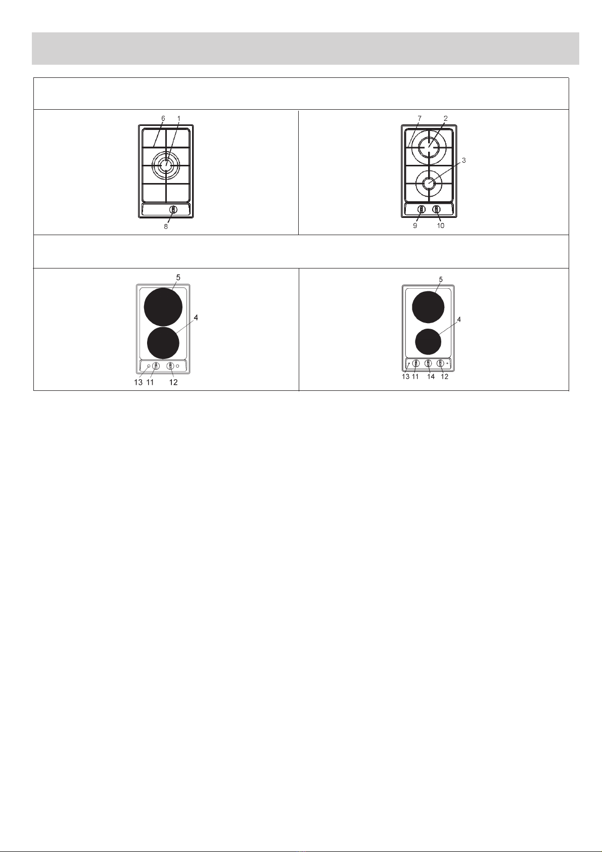
INSTRUCTIONS AND ADVICE FOR THE
USE, INSTALLATION AND MAINTENANCE
OF MIXED AND GAS FUELLED
BUILT-IN HOT PLATES
GB

3
DESCRIPTION OF THE HOT PLATES
1 Ultra rapid burner of 3350 W
2 Rapid gas burner of 3000 W
3 Auxiliary gas burner of 1000 W
4 Electric plate Ø 145 mm
5 Electric plate Ø 180 mm
6 Enamelled steel pan support 1F
7 Enamelled steel pan support 2F
8 Burner n° 1 control knob
9 Burner n° 3 control knob
10 Burner n° 2 control knob
11 Electric plate n° 5 control knob
12 Electric plate n° 4 control knob
13 Electric plate operation warning light
14 Timer
FV3XG/FV3EG/FV3XW/FV3EG
FV3XE/FV3EE

FV3VR/FV3VR
6 1 7
3
1 Hi-light electric heating element Ø 140 mm 1200 W
2 Hi-light electric heating element Ø 180 mm 1700 W
3 Hi-light electric heating element double cooking zone (conc.) Ø 180/120 mm 1700 W ("Hilight" as well)
4 Hi-light electric heating element double cooking zone (oval) Ø 265/170 mm 2200 W
5 Switch for el. element n.2
6 Switch for el. element n.1
7 Switch for el. element n.3
8 Switch for el. element n.4
9 Residual heat indicator

FV3XB/FV3EB
1 Grill 2400 W
2 Grill rack
3 Grill control knob
4 Grill on/off indicator lamp

FV3XF/FV3EF
Caution: All appliances are designed for personel household use only.


2
3
4
FIG.2 FIG.3 FIG.4


1) ELECTRIC HOB (for ceran glass products)
The hot plates are equipped with 2 hi-light heating elements with different powers and diametres.
On the frontal panel, close to each knob, has been silk-screened a scheme where is indicated to
which cooking zone the knob refers (fig. 5).
In some particular models the scheme annexes a light indicator that turns on when the cooking
zome temperature is above 60°C.
The indicator will turn off only when the temperature of the cooking zone will be below the value:
thes is the reason why we call it residual heat indicator. Some other models they have only one
indicator.
Connection of electric heating elements
Heating elements are controlled by energy regulators that permit to obtain a big range of different
temperatures.
To connect the heating elements es necessary to turn clockwise or anticlockwise the relaive knob.
Indicator light 9 shows the connection of one or more heating elements.
To connect the heating elements with double cooking zone is necessary to turn clockwise the knob
to the " " sign and release again.
How to use the cooking zones
Heating takes place only in the inside part of the circles drawn on the special glass. The circles
have to be wholly covered by the pots.
FIG.5

6
FIG. 6

1) BURNERS(for gas products)
A diagram is screen-printed above each knob on the
front panel. This diagram indicates to which burner
the knob in question corresponds. After having
opened the gas mains or gas bottle tap, light the
burners as described below:
- Manual ignition
Push and turn the knob corresponding to the
required burner in an anticlockwise direction until it
reaches the full on position (large flame fig.7), then
place a lighted match near the burner.
- Electrical ignition
Push and turn the knob corresponding to the
required burner in an anticlockwise direction until it
reaches the full on position (large flame fig.7), then
depress and release the ignition button.
- Automatic electrical ignition
Push and turn the knob corresponding to the
required burner in an anticlockwise direction until it
reaches the full on position (large flame fig.7), then
depress the knob.
- Lighting burners equipped with flame failure
device
The knobs of burners equipped with flame failure
device must be turned in an anticlockwise direction
until they reach the full on position (large flame fig.7)
and come to a stop. Now depress the knob in
question and repeat the previously indicated
operations.
Keep the knob depressed for about 10 seconds once
the burner has ignited.
HOW TO USE THE BURNERS
Bear in mind the following indications in order to
achieve maximum efficiency with the least possible
gas consumption:
- Use adequate pans for each burner (consult the
following table and fig.8).
- When the pan comes to the boil, set the knob to the
reduced rate position (small flame fig.7).
- Always place a lid on the pans.
Burners Power ratings Pans Ø in cm
Ultra rapid 3350 24 ÷ 26
Rapid 3000 20 ÷ 22
Semirapid 1750 16 ÷ 18
Auxiliary 1000 10 ÷ 14
WARNINGS:
- Burners with flame failure device may only be
ignited when the relative knob has been set to
the Full on position (large flame fig. 7).
- Matches can be used to ignite the burners in a
blackout.
- Never leave the appliance unattended when the
burners are being used. Make sure there are no
children in the near vicinity. Particularly make
sure that the pan handles are correctly
positioned and keep a chek on foods requiring
oil and grease to cook since these products can
easily catch fire.
- Never use aerosols near the appliance when it is
operating.
- If the built-in hot plate has a lid, any spilt food
should be immediately removed from this
before it is opened. If the appliance has a glass
lid, this could shatter when the hot plate
becomes hot. Always switch off all the burners
before closing the lid.
USE
FIG. 7FIG. 8

USE
Notes:
Use of a gas cooking appliance produces heat and moisture in the room in which it is installed. The
room must therefore be well ventilated by keeping the natural air vents clear (fig. 9) and by activating
the mechanical aeration device (suction hood or electric fan fig. 10 and fig. 11).
Intensive and lengthy use of the appliance may require additional ventilation. This can be achieved by
opening a window or by increasing the power of the mechanical exhausting system if installed.
FIG. 9FIG. 10 FIG. 11
(*) Air inlet - minimum section 100 cm2

USE
2) HOW TO USE THE ELECTRIC
PLATES
Mixed hot plates may be equipped with a normal or
rapid electric plates. There are controlled by
switches with various positions (see fig.12) and is
switched on by turning the knob to the required
setting. A diagram is screen-printed above each
knob on the front panel. This diagram indicates to
which electric plates the knob in question
corresponds (see fig.12). A red warning light will
come on to indicate that the plate is operating.
A purely indicative regulation table for the normal
electric plates is given below.
NORMAL AND
RAPID PLATES
HEAT
INTENSITY
HEAT
INTENSITY
TABLE
0
1
2
3
4
5
6
Off
Weak
Low
Slow
Medium
Strong
High
To dissolve butter, chocolate, etc.. To heat small
amounts of liquid.
To heat larger amounts of liquid. To prepare cremes
and suces requiring long slow cooking times.
To thaw frozen foods and prepare stews, heat to boiling
point or simmer.
To heat foods to boiling point. To brown delicate meats
and fish.
For escalopes and steaks. To simmer large amounts of
food.
To bring large amounts of liquid to the boil. For frying.
FIG. 12

CLEANINGUSE
WARNINGS:
When the plate is switched on for the first time,
or if it has remained unused for a long period, it
should be dried for 30 minutes on switch position
n° 1. This will eliminate any moisture that may
have been absorbed by the insulating material.
To correctly use the appliance, remember:
- To place a pan on the plate before switching
this on.
- To always use pans with flat and very thick
bottoms (see fig. 13).
- To never use pans that are smaller than the
plate diameters.
- To dry the bottom of the pan before placing it
on the plate.
- Never leave the appliance unattended when
the plates are being used. Make sure that there
are no children in the near vicinity. Particularly
make sure that the pan handles are correctly
positioned and keep a check on foods requiring
oil and grease to cook since these products can
easily catch fire.
- The plates will remain hot for a long period of
time even use after use, never touch them with
the hands or other objects in order to prevent
burns.
- Immediately disconnect the appliance from the
electricity main as soon as cracks are noted on
the surfaces of the plates.
- If the built-in hot plate has a lid, any spilt food
should be immediately removed from this
before it is opened. If the appliance has a glass
lid, this could shatter when the cooker
becomes hot. Always switch off all the plates
before closing the lid.
IMPORTANT:
Always disconnect the appliance from the gas
and electricity mains before carrying out any
cleaning operation.
3) HOT PLATE
Periodically wash the hot plate, the enamelled stell
pan support, the enamelled burner caps “C” and the
burner heads “M” (see fig.14) with lukewarm soapy
water. Following this, all parts should be thoroughly
rinsed and dried. Never wash them while they are still
warm and never use abrasive powders. Do not allow
vinegar, coffee, milk, salted water, lemon or tomato
juice from remaining in contact with the enamelled
surfaces for long periods of time.
WARNINGS:
Comply with the following instructions, before
remounting the parts:
- Check that burner head slots have not become
clogged by foreign bodies.
- Check that enamelled burner cap “C” (fig. 14)
have correctly positioned on the burner head. It
must be steady.
- The exact position of the pan support is
established by the rounded corners, which
should be set towards the side edge of the hot
plate.
- Do not force the taps if they are difficult open
or close. Contact the technical assistance
service for repairs.
- Correctly preserve the plate after use by
treating it with special products, easily
available on the market. This will keep the
surface of the plate clean and bright. The
operation will also prevent the formation of
rust.
FIG. 13
FIG. 14

15
16
FIG.15 FIG.16


TECHNICAL INFORMATION FOR
THE INSTALLER
Installation, adjustments of controls and
maintenance must only be carried out by a
qualified engineer.
Incorrect installation may cause damage to
persons, animals or property for which the
Manufacturer shall not be considered
responsible.
During the life of the system, the automatic
safety or regulating devices on the appliance
may only be modified by the manufacturer or by
his duly authorized dealer.
4) INSTALLING THE HOT PLATE
Check that the appliance is in a good condition after
having removed the outer packaging and internal
wrappings from around the various loose parts. In
case of doubt, do not use the appliance and contact
qualified personnel.
Never leave the packaging materials (cardboard,
bags, polystyrene foam, nails, etc.) within
childrenÕs reach since they could become
potential sources of danger.
The measurements of the opening made in the top
of the modular cabinet and into which the hot plate
will be installed are indicated in either fig. 17.
Always comply with the measurements given
for the hole into which the appliance will be
recessed.
The appliance belongs to class 3 and is therefore
subject to all the provisions established by the
provisions governing such appliances.
5) SEALING THE HOT PLATE
The hot plate has a special seal which prevents liquid
from infiltrating into the cabinet. Strictly comply with
the following instructions in order to correctly apply
this seal:
- Detach the seals from their backing, checking that
the transparent protection still adheres to the seal
itself.
- Overturn the hot plate and correctly position seal
“E” (fig. 18) under the edge of the hot plate itself, so
that the outer side of the seal perfectly matches the
outer perimetral edge of the hot plate. The ends of
the strips must fit together without overlapping.
- Evenly and securely fix the seal to the hot plate,
pressing it in place with the fingers.
INSTALLATION
FIG. 17 FIG. 18
This manual suits for next models
12
Table of contents
Other Kuppersberg Cooktop manuals
Popular Cooktop manuals by other brands

Electrolux Professional
Electrolux Professional N7E Installation and operating manual

GE
GE JP626 Use and care guide

Bertazzoni
Bertazzoni P24400X Installation, service and user instructions

KitchenAid
KitchenAid KECC056, KECC506, KECC507, KECC508, KECC556, KECC567,... Use & care guide

Miele
Miele MasterChef KM452 installation instructions

Dometic
Dometic MO8952 operating manual