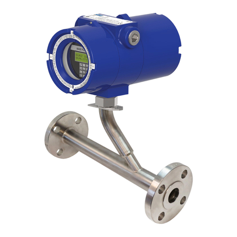
Kurz 255 Series User manual

Series 255 Flow Averaging Transmitter
Operations Guide
368057B

Series 255 Flow Averaging Transmitter Operations Guideii
Copyrights and Trademarks
Copyright © 2019 Kurz Instruments, Inc.
All rights reserved.
No part of this publication may be reproduced or transmitted in any form or by any means, electronic or mechanical,
including photocopying, recording, or by any information storage and retrieval system without express written
permission from Kurz Instruments, Inc., 2411 Garden Road, Monterey, California 93940; Phone: 831-646-5911,
Fax: 831-646-8901, or www.KurzInstruments.com
The material in this manual is for information only and is subject to change without notice. Every reasonable effort has
been made to ensure that the information in this manual is complete and accurate. Kurz Instruments, Inc. makes no
representations or warranties of any kind concerning the contents of this publication, and therefore assumes no
liability, loss, or damages resulting from use, errors, or omissions in this publication or from the use of the information
contained herein. Kurz Instruments, Inc.,is not responsible for printing or clerical errors.
Kurz Instruments, Inc., reserves the right to make engineering changes, product improvements, and product design
changes without reservation and without notification to its users. Consult your Kurz Instruments, Inc. representative or
a Kurz applications engineer for information regarding current specifications.
Kurz Instruments, Inc. assumes no liability for damages or injuries (consequential or otherwise) caused by the improper
use and/or improper installation of this product or where this product is used in any application other than what it was
designed for and intended. Kurz Instruments, Inc. expressly denies any responsibility if this product has been modified
without Kurz Instruments, Inc. written approval or if this product has been subjected to unusual physical or electrical
stress, or if the original identification marks have been removed or altered.
Equipment sold by Kurz Instruments, Inc. is not intended for use in connection with any nuclear facility or activity
unless specifically sold for such applications and specific conditions for such usage are detailed. If the equipment is
used in a nuclear facility or activity without supporting quotation, Kurz Instruments, Inc. disclaims all liability for any
damage, injury, or contamination, and the buyer shall indemnify and hold Kurz Instruments, Inc., its officers, agents,
employees, successors, assigns, and customers, whether direct or indirect, harmless from and against any and all
losses, damages, or expenses of whatever form and nature (including attorneys fees and other costs of defending any
action) which they, or any of them, may sustain or incur, whether as a result of breach of contract, warranty, tort
(including negligence), strict liability or other theories of law, by reason of such use.
The Kurz logo is a trademark of Kurz Instrument, Inc., registered in the U.S. and other countries. Use of the Kurz logo
for commercial purposes without the prior written consent of Kurz Instruments, Inc. may constitute trademark
infringement in violation of federal and state laws. MetalClad, B-Series, Series 454FTB, Series 454FTB-WGF,
Series 504FT, Series 534FTB, K-BAR 2000B, and K-BAR 2000B-WGF are trademarks of Kurz Instruments, Inc.
Other company and product names mentioned herein are trademarks of their respective owners. Mention of third-
party products is for informational purposes only and constitutes neither an endorsement nor a recommendation.
Kurz Instruments, Inc., assumes no responsibility with regard to the performance or use of these products.
Kurz Instruments Inc. Kurz Support
2411 Garden Road Customer Service
Monterey, CA 93940 800-424-7356 (toll free)
831-646-5911 (main) www.kurzinstruments.com
831-646-8901 (fax) service@kurzinstruments.com
Guide written by Robert

Series 255 Flow Averaging Transmitter Operations Guide iii
Table of Contents
Preface ..................................................................................... viii
Overview ........................................................................................................ ii-viii
Before You Begin ............................................................................................ ix
Series 255 Description ................................................................................... ix
Using this Manual .......................................................................................... ix
Manual Conventions ...................................................................................... x
Glossary .......................................................................................................... xi
Chapter 1
Panel Display & Operating Modes ............................................ 1-1
Overview ........................................................................................................ 1-1
Front Panel .................................................................................................... 1-2
Display ..................................................................................................... 1-2
Keypad .................................................................................................... 1-3
Status Indicators ..................................................................................... 1-5
Operating Modes ........................................................................................... 1-6
Run Mode ............................................................................................... 1-6
Display Mode .......................................................................................... 1-6
Program Mode ........................................................................................ 1-7
Program Mode — Basic Access ........................................................ 1-8
Program Mode — Advanced Access ................................................ 1-9
Chapter 2
Display Mode ........................................................................... 2-1
Overview ........................................................................................................ 2-1
Display Mode ................................................................................................. 2-2
Option 1 — Channel Velocity Summary .................................................. 2-4
Option 2 — Channel Temperature Summary ......................................... 2-4
Option 3 — Channel Velocity and Temperature Summary ..................... 2-5
Option 4 — Channel Operational Summary ........................................... 2-5
Option 5 — Channel Detail ..................................................................... 2-6
Option 6 — Average Velocity Summary .................................................. 2-7
Option 7 — Totalizer and Daily Total Summary ...................................... 2-7
Option 8 — Process Gas Information ...................................................... 2-8
Option 9 — System Information ............................................................. 2-8

Series 255 Flow Averaging Transmitter Operations Guide iv
Chapter 3
Program Mode Basic Access ..................................................... 3-1
Overview ........................................................................................................ 3-1
Program Mode — Basic Access ...................................................................... 3-2
Option 1 — Tag Name ............................................................................. 3-6
Option 2 — Flow Units ............................................................................ 3-7
Option 3 — Flow Area Setup ................................................................... 3-8
Option 4 — Analog Output Setup ........................................................... 3-9
Option 5 – Flow Set Point Setup ............................................................. 3-12
Option 6 – Temperature Set Point Setup ................................................ 3-13
Option 7 — Alarm Setup ......................................................................... 3-14
Option 8 — Totalizer Setup ..................................................................... 3-15
Option 9 — Reset Totalizer ..................................................................... 3-15
Option 10 — Field Calibration Correction Factor .................................... 3-16
Option 11 — Variable Correction Factor Setup ...................................... 3-17
Option 12 — Run Mode Display Setup ................................................... 3-18
Option 13 — Clock Setup ........................................................................ 3-19
Chapter 4
Program Mode Advanced Access .............................................. 4-1
Overview ........................................................................................................ 4-1
Program Mode — Advanced Access .............................................................. 4-2
Option 1 — Tag Name ............................................................................. 4-10
Option 2 — Flow Units ............................................................................ 4-11
Option 3 — Flow Area Setup ................................................................... 4-12
Option 4 — Analog Output Setup ........................................................... 4-13
Option 5 – Flow Set Point Setup ............................................................. 4-16
Option 6 – Temperature Set Point Setup ................................................ 4-17
Option 7 — Alarm Setup ......................................................................... 4-18
Option 8 — Totalizer Setup ..................................................................... 4-19
Option 9 — Reset Totalizer ..................................................................... 4-19
Option 10 — Field Calibration Correction Factor .................................... 4-20
Option 11 — Variable Correction Factor Setup ...................................... 4-21
Option 12 — Run Mode Display Setup ................................................... 4-22
Option 13 — Clock Setup ........................................................................ 4-23
Option 14 — Reference Temperature & Pressure .................................. 4-24
Option 15 — Minimum Kickout Count .................................................... 4-24
Option 16 — NE-43 Alarm Level ............................................................. 4-25
Option 17 — Modbus Communication ................................................... 4-26
Option 18 — Serial USB Baud Rate ......................................................... 4-27
Option 19 — System Operational State .................................................. 4-27
Option 20 — Number of Channels .......................................................... 4-28
Option 21 — Channel Setup .................................................................... 4-29
Option 22 — User Access Codes ............................................................. 4-30
Option 23 — Analog Output Calibration ................................................. 4-31
Option 24 — Analog Output Test ............................................................ 4-32

Series 255 Flow Averaging Transmitter Operations Guide v
Option 25 — NE-43 Alarm Test ............................................................... 4-33
Option 26 — Restore Auxiliary Configuration ......................................... 4-33
Option 27 — Restore Factory Configuration ........................................... 4-34
Option 28 — Save to Auxiliary Configuration ......................................... 4-34
Option 29 — Output Report to USB ........................................................ 4-35
Option 30 — USB Data Log Setup ........................................................... 4-38
Options 31 and 32 – Sensor Purge Cleaning ........................................... 4-39
Option 31 – Purge Timer Setup ....................................................... 4-39
Option 32 – Purge Manual Command ............................................. 4-40
Options 33 Thru 35 - Zero/Mid/Span Check ........................................... 4-41
Option 33 – Zero-Span Schedule Setup ........................................... 4-43
Option 34 – Zero-Span Test Parameters Setup ................................ 4-44
Option 35 – Zero-Span Manual Command ...................................... 4-46
Chapter 5
USB Connection for Terminal Emulators ................................... 5-1
Overview ........................................................................................................ 5-1
USB Connection ............................................................................................. 5-2
Configuring Tera Term ................................................................................... 5-3
Modbus RS-485 Service Port .......................................................................... 5-5
Chapter 6
Diagnostics & Troubleshooting ................................................. 6-1
Overview ........................................................................................................ 6-1
Event Notification .......................................................................................... 6-2
Local Display Event Line .......................................................................... 6-2
Series 255 Alarm Outputs ....................................................................... 6-3
NAMUR NE-43 ......................................................................................... 6-3
Channel Kickout ...................................................................................... 6-4
NAMUR NE-107 ....................................................................................... 6-4
Data Quality Status Byte ......................................................................... 6-5
Series 255 Main Board Overview ................................................................... 6-6
AC Power Connections ............................................................................ 6-7
DC Power Connections ............................................................................ 6-7
System Input and Output Communications ............................................ 6-8
System Communications Area ................................................................ 6-9
Sensor Power and Communications Connections .................................. 6-10
Troubleshooting ............................................................................................ 6-11
Safety Requirements .............................................................................. 6-11
Channel Kickout ...................................................................................... 6-12
Modbus Communication Between the Series 255 and the Flow Sensors 6-13

Series 255 Flow Averaging Transmitter Operations Guideevi
List of Tables
Chapter 1
Panel Display & Operating Modes
Table 1-1. Keypad Character Map .............................................................. 1-4
Table 1-2. Status Indicator Descriptions .................................................... 1-5
Table 1-3. Display Mode Functions ............................................................ 1-6
Table 1-4. Program Mode — Basic Access Functions ................................. 1-8
Table 1-5. Program Mode — Advanced Access Functions ......................... 1-10
Chapter 2
Display Mode
Table 2-1. Display Mode ............................................................................. 2-2
Chapter 3
Program Mode Basic Access
Table 3-1. Program Mode — Basic Access ................................................. 3-3
Table 3-2. 4-20 mA Output Functions ........................................................ 3-9
Chapter 4
Program Mode Advanced Access
Table 4-1. Program Mode — Advanced Access ......................................... 4-3
Table 4-2. 4-20 mA Output Functions ........................................................ 4-13
Table 4-3. Channel IDs and Corresponding Modbus Addresses ................. 4-26
Table 4-4. Channels Per Series 255 Model ................................................. 4-28
Chapter 5
USB Connection for Terminal Emulators
Chapter 6
Diagnostics & Troubleshooting
Table 6-1. System Events and Triggers ....................................................... 6-2
Table 6-2. Alarm Triggers ........................................................................... 6-3
Table 6-3. Front Panel Status LEDs Description ......................................... 6-4

Series 255 Flow Averaging Transmitter Operations Guide vii
List of Figures
Chapter 1
Panel Display & Operating Modes
Figure 1-1. Series 255 Display ...................................................................... 1-2
Figure 1-2. Series 255 Keypad ..................................................................... 1-3
Figure 1-3. Series 255 Status Indicators ...................................................... 1-5
Chapter 2
Display Mode
Chapter 3
Program Mode Basic Access
Chapter 4
Program Mode Advanced Access
Figure 4-1. Sample Configuration Output ................................................... 4-36
Figure 4-2. Sample Zero-Span Report .......................................................... 4-37
Chapter 5
USB Connection for Terminal Emulators
Figure 5-1. USB Cable on Microprocessor Board ......................................... 5-2
Figure 5-2. Service Port Locations ............................................................... 5-5
Chapter 6
Diagnostics & Troubleshooting
Figure 6-1. Series 255 Motherboard Overview ........................................... 6-6
Figure 6-2. AC Power Connections .............................................................. 6-7
Figure 6-3. DC Power Connections .............................................................. 6-7
Figure 6-4. System Input and Output Communications .............................. 6-8
Figure 6-5. System Communications Area ................................................... 6-9
Figure 6-6. Sensor Power and Communications Connections ..................... 6-10

Series 255 Flow Averaging Transmitter Operations Guide viii
Preface
Overview
This guide provides instructions for operating the Series 255 Flow Averaging Transmitter. The
unit should be installed as instructed in the Series 255 Flow Averaging Transmitter Hardware
Guide.

Series 255 Flow Averaging Transmitter Operations Guideix
Before You Begin
Important Confirm the device has been installed in accordance with the installation requirements
specified in the Series 255 Flow Averaging Transmitter Hardware Guide. Incorrect
installations will effect the reliability of flow data.
Series 255 Description
The Kurz Series 255 Flow Averaging Transmitter is designed for gas flow measurements in ducts or stacks
where two or more sensing points are required due to a large duct size or where irregular flow profiles are
present. The Series 255 is a microprocessor-based flow transmitter that continuously collects process flow
and temperature measurements from multiple independent Kurz flow meters and calculates a grand
average of the flow and temperature in the duct.
The Series 255 works in conjunction with two or more Kurz Instruments B-Series flow meters – either the
Kurz 454FTB, K-BAR 2000B, or K-BAR 2000B-WGF insertion meters. The four models in the Series 255
product line support up to 4, 9, or 16 flow sensors for performing the following functions:
•Provide 24 VDC power to each flow sensor.
•Flow and temperature averaging.
•Kickout from the average any channels in error or being serviced.
•Provide 4-20 mA analog output signal of the averaged flow and temperature.
•Flow totalization – both resettable and non-resettable 30-day log of daily flow totals.
Using this Manual
Kurz Instruments, Inc., documentation includes manuals and product literature, Adobe Acrobat PDF files,
and application online Help files. The Kurz Instruments CD contains all the available documentation files.
To read PDF files, download the free Adobe Acrobat Reader from www.adobe.com.
The Kurz Instruments Web site provides additional information:
•World Wide Web: www.KurzInstruments.com
•Email: service@KurzInstruments.com
•Documentation links to the most current manuals and literature
You can access device support in the following ways:
•Main: 831-646-5911
•Phone: 800-424-7356
•Fax: 831-646-8901

Series 255 Flow Averaging Transmitter Operations Guide x
Manual Conventions
The following table lists conventions used in the Kurz documentation and provides an example or
description of each convention.
Table 1. Conventions used in this manual
Convention / Example Description
Check the Configuration File checkbox Text that you type, click, or select (for example, field names,
menus, and commands) appear in bold.
PRESS ENTER TO
SET METER DATA Text appearing in a display or window is shown in courier.
Select Start→All Programs→Kurz
Instruments→KzComm
An arrow (→) is used to separate a menu name from its
submenu commands.
Programs Files\Kurz Instruments\KzComm Simplified directory structures and path names are used in
examples. Your folder names may be different.
Note Information.... Indicates additional information to clarify a procedure,
action, event, or concept and ensure appropriate
understanding.
Important Information.... Indicates information relevant to proper operation, actions,
and responses.
Caution Information.... Indicates an action or procedure can result in incorrect
operation or destruction of the device if not performed
properly. Comply strictly with the instructions.
Warning Information.... Indicates an action or procedure can result in injury or a
safety hazard if not performed properly.
Comply strictly with the instructions and proceed with care.

Series 255 Flow Averaging Transmitter Operations Guidexi
Glossary
Alarms There are two alarms on the Series 255 that are each linked to an
optically coupled solid state relay (SSR). The relays can be used to
interface with external warning lamps or audible devices when an alarm
event occurs.
Note The relays are optically isolated solid-state relays (SPST switching),
their non-powered state is an open circuit and must be
considered for fail-safe alarm logic configurations.
The alarm relays are rated for 0.5 A
Channel Refers to one of the flow meters or flow sensing units that the Series 255
provides power to and communicates with to obtain velocity,
temperature, and status data. There are up to 16 channels assigned
letters A through P. Each flow meter or channel is assigned a unique and
fixed address starting at address 11 through 26.
Kurz multipoint flow meters have two to four flow sensing units
Kurz single-point flow meters one flow sensing unit.
Channel Kickout This specifies when a defective flow meter is removed from the flow and
temperature average calculations.
Daily Totalization The Series 255 accumulates a total flow for each day. The daily total
begins accumulating at midnight each day. One month of daily
totalization is recorded in the EEPROM and can be downloaded
to a text file.
Factory configuration Default parameter values of the device, usually based on customer order
specifications.
Flow Meter / Flow Sensor The individual flow sensing device also referred to as a channel.
Flow units The flow units determine whether the Series 255 system engineering
units are metric or imperial measurements and the units that appear for
velocity and temperature. The flow units can be volumetric rate or mass
rate. The flow rate options are NCMH, NLPM, SCFH, SCFM, SCMH, and
SLMP. The mass rate options are KGH, KGM, PPH, and PPM.
Haz Loc Hazardous (and potentially hazardous) Location environment due to the
presence or possible presence of flammable gases and vapors, and
combustible dusts.
NE-43 NAMUR NE-43 is a German fault detection standard that lets the user
know if there is a fault within the instrument by forcing the 4-20 mA
output current outside the normal operating range of the instrument.

Series 255 Flow Averaging Transmitter Operations Guide xii
Output There are two 4-20 mA analog outputs on the Series 255. Each is user
assignable to flow rate, velocity, or temperature, and user scalable to
represent the full range or any subset. They are isolated and have fault
indication per NAMUR NE-43 guidelines.
Ord Loc Ordinary Industrial Location environments where rough usage, moisture,
dust, dirt, and corrosion are a potential problem and where there is no
presence of flammable gases or combustible dusts.
Port The Series 255 main board has six ports that each provide an isolated
RS-485 and 24 VDC to individual channels or channel groups.
RTC The real-time clock provides a time stamp of date and time for events
logged to the event log in the Series 255 non-volatile memory.
Totalizer The Series 255 keeps a running accumulation of the total flow. There are
two records of total flow that the Series 255 maintains – one that is not
resettable and one that can be reset by the user.

Series 255 Flow Averaging Transmitter Operations Guide 1–1
Chapter 1
Panel Display &
Operating Modes
Overview
This section describes the display, keypad, and status indicators on the Series 255 Flow
Averaging Transmitter, and provides a basic description for each operating mode:
•Run mode
•Display mode (view only)
•Program mode
Important All option parameters and examples use sample values and measurement units.
The actual values and measurement units you see reflect the configuration of the
255.
This chapter is intended for users accessing the 255 menus using the local keypad and display.

Series 255 Flow Averaging Transmitter Operations Guide 1–2
Panel Display & Operating Modes
Front Panel
All Series 255 models include a front panel display with four rows of 20 characters and a 20-key keypad
(several keys have dual functions).
Display
The large display characters (approximately 8 mm x 5 mm) facilitate easier viewing from a distance.
Figure 1-1 shows the display when the Series 255 is in Run Mode.
Figure 1-1. Series 255 Display
The first three lines show process data and menu options. The fourth line shows device messages and
events.
F L O W 1 2 3 4 5 6 7.8 SCFM
T O T A 1 2 3 4 5 6 78 S C F
L
T E M P 1 2 3 .4 D G F
N O E N T S
EV
E

Series 255 Flow Averaging Transmitter Operations Guide1–3
Panel Display & Operating Modes
Keypad
The membrane keypad has 20 function keys. The keys are used for navigating a menu system and for
viewing or changing application parameters.
Figure 1-2. Series 255 Keypad
The key functions are as follows:
•The P key accesses Program mode for making Basic or Advanced configuration changes to the
Series 255. Basic and Advanced setup each have code-specific access. The P key also navigates
through menu parameter fields or through multiple pages of a menu.
•The D key accesses Display mode for view-only flow, velocity, and temperature information.
See Chapter 2, Display Mode, for more information.
•The E key is used as an Enter key to accept and save changes after entering data.
•The H key is used to back out of a Program mode menu and return to the menu option selection
without making any changes and to exit out of Program mode and return to Run mode.
•The C key is used to clear a data entry field.
•The numeric keys are used for entering number or text data.
•The UP and DN keys are used to scroll through a menu. The scroll option is available when the
symbol ^v appears on the display.
•The Plus/Minus (+/-) key is used for entering negative values or a hyphen in a string input.
•The Dot () key is used for entering a decimal or period.
1 2 3
4 5 6
7 8 9
0
H
C
P
D
L
E+/-
DEFABC
MNO
WXYZTUVPQRSLOG
ENTER
PAGE
JKLGHI
CLEAR
HOME
UP
DN

Series 255 Flow Averaging Transmitter Operations Guide 1–4
Panel Display & Operating Modes
The numeric keys include 0 through 9, with keys 2 through 9 also being used for letters A to Z. For data
entry fields that accept alphabetic/numeric data strings, continue pressing the numeric key to cycle
through the letters. For example, pressing the 7 key continuously will cycle through the characters 7, P, Q,
R, and S. Press the E key to accept the current letter or number and advance to the next character
position. Keys 0 and 1 provide symbols, including a space, as defined in Table 1-1 table.
The display/menu navigation is done by selecting an option number. The menu options are listed in
Table 1-3, Table 1-4, and Table 1-5.
Table 1-1. Keypad Character Map
Key Character Map Key Character Map
0 0, < sp >, (, ), +, ,, <, > 5 5, J , K, L
1 1, / , #, :, $ , @, % , & 6 6, M , N , O
2 2, A , B, C 7 7, P , Q , R, S
3 3, D , E , F 8 8, T , U, V
4 4, G , H, I 9 9, W , X, Y, Z

Series 255 Flow Averaging Transmitter Operations Guide1–5
Panel Display & Operating Modes
Status Indicators
There are five status indicators just below the display. These indicators provide an “at-a-glance” overview
of the health of the Series 255 System and its components. The indicators are color coded according to
NAMUR NE-107 specification.
Figure 1-3. Series 255 Status Indicators
The status indicator category and descriptions are listed in Table 1-2.
Table 1-2. Status Indicator Descriptions
Status Indicator Description Device Message/ Event
Failed
(red, X mark)
Signal is invalid due to a malfunction in the device,
sensor, or actuator.
SYSTEM SENSOR FAIL
SYSTEM COMM FAIL
Out of Specification
(yellow, question mark)
Permissible ambient or process conditions
exceeded, or the measuring uncertainty of sensors
or deviations from the set value in actuators is
probably greater than expected.
FLOW OUT OF RANGE
TEMP OUT OF RANGE
CHANNEL KICKOUT AT
MIN
Maintenance required
(blue, oil can)
Advisory. Although the signal is valid, the
remaining life is nearly exhausted or a function will
soon be restricted due to operational conditions.
CHANNEL KICKOUT
ELECT TEMP HI
TOTALIZER ABOVE HI
SETPOINT
Check Function
(amber/orange, wrench)
Signal temporarily invalid due to on-going work on
the device.
SYSTEM MAINTENANCE
ZERO-SPAN TEST ACTIVE
Normal
(green, check mark) System is normal, signal is valid. NO EVENTS
NormalFailed Out of Maintenance Check
FunctionRequiredSpecification

Series 255 Flow Averaging Transmitter Operations Guide 1–6
Panel Display & Operating Modes
Operating Modes
The Series 255 has three modes:
•Run mode – Normal operational state of the Series 255.
•Display mode – Provides a view-only mode of system data and parameters.
No access code is required for Display mode.
•Program mode – There are two levels of Program mode - Basic setup and Advanced setup.
Each setup level has a specific access code.
Run Mode
Run mode is the normal operational state of the Series 255 that appears after completing the power-up
and system checks. The default Run mode display shows the Series 255 tag name, flow, and temperature,
for the duct/pipe that the Series 255 is monitoring. The user can select the process data that appears on
the display, including Flow, Temperature, Tag Name, Totalized Flow, and Daily Totalized Flow. Alternatively,
all of the process data can scroll on the display.
Display Mode
Display mode provides view-only access to summary information.
To enter into Display mode:
1> Press D.
ENTER DISPLAY OPTION
1-9> 1
2> Enter a number between 1 and 9, and then press E.
Table 1-3. Display Mode Functions
Option # Function Option # Function
1 Channel Velocity Summary 6 Average Velocity Summary
2 Channel Temperature Summary 7 Totalizer and Daily Total Summary
3 Channel Velocity and Temperature Summary 8 Process Gas Information
4 Channel Operational Summary 9 System Information
5 Channel Detail

Series 255 Flow Averaging Transmitter Operations Guide1–7
Panel Display & Operating Modes
Program Mode
Program mode allows you to make configuration and parameter changes to the Flow Averager. This is an
access code-protected mode. The access code determines the amount of access you have in Program
mode.
•The default Basic access code is 123456.
Basic access is used to configure the essential Flow Averager parameters.
•The default Advanced access code is 654321.
Advanced access is used for changing advanced Flow Averager parameters.
Before making any configuration changes in Program mode, it is important to remember:
•Any configuration changes are automatically saved to EEPROM when the Flow Averager exits out of
Program mode. There are no prompts to confirm changes.
Important The process flow and temperature values are measured and output while the Series 255 is in
Program mode.
Changing parameters such as Duct Flow Area will influence the output signal and may cause
a significant change in the signal immediately after entering the change.
•To back out of a series of menus, continue to press H for each level (manual exit).
•If there is no menu activity for 3 minutes, the display automatically exits to Run mode.
Any changes made before the auto-exit are saved to EEPROM.
•The configuration is retained through Flow Averager reboots and power cycles.
Important You should not make any changes to the Flow Averager configuration without a complete
understanding of the parameters. Changing a setting incorrectly can cause the Flow
Averager to malfunction.
To enter Program mode:
1> Press P.
2> Enter the Basic access code or Advanced access code.
3> Press E.
4> You can jump to any of the options shown in Table 1-4 and Table 1-5.
Note Not all parameters may appear based on the Flow Averager configuration.
In most cases, when you reach the end of the parameters for a menu, the prompt
automatically returns to the main option menu. In instances where you continue to
cycle through the parameters, press H to exit the menu.
Important In the event unwanted changes are made, Kurz provides the ability to reset the Series 255 to
the original Factory settings, as described in Chapter 4, Program Mode Advanced Access,
“Option 27 — Restore Factory Configuration.”
When you want to save a record of customized settings, Kurz provides an option for
establishing a restore point. See Chapter 4, Program Mode Advanced Access,“Option 28 —
Save to Auxiliary Configuration” and “Option 26 — Restore Auxiliary Configuration.”

Series 255 Flow Averaging Transmitter Operations Guide 1–8
Panel Display & Operating Modes
Program Mode — Basic Access
Before making any configuration changes in Program mode, it is important to remember:
•Any configuration changes are automatically saved to EEPROM when the Series 255 exits out of
Program mode. There are no prompts to confirm changes.
•To back out of a menu, press H one or more times to return to the function prompt.
•To return to Run mode from the main function prompt, press H.
•If there is no keypad activity for 3 minutes, the display automatically exits to Run mode.
Any changes made before the auto-exit are saved to EEPROM.
The configuration is retained through power cycles of the Series 255.
To enter Program mode with Basic access:
1> Press P.
ENTER ACCESS CODE
>******
2> Enter the Basic access code, and then press E.
The default Basic access code is 123456.
ENTER PROGRAM OPTION
1-13> 1
3> Enter the option number as defined in Table 1-4, and then press E.
Table 1-4. Program Mode — Basic Access Functions
Option # Function Option # Function
1 Tag Name 8 Totalizer Setup
2 Flow Units 9 Reset Totalizer
3 Flow Area Setup 10 Field Calibration Correction Factor
4 Analog Output Setup 11 Variable Correction Factor Setup
5 Flow Set Point Setup 12 Run Mode Display Setup
6 Temperatue Set Point Setup 13 Clock Setup
7 Alarm Setup
Table of contents
Other Kurz Transmitter manuals
Popular Transmitter manuals by other brands

SGM LEKTRA
SGM LEKTRA MTU5 quick start guide

YOODA
YOODA MAGNETIC-PRO-15Rw YSH manual

Wavetronix
Wavetronix Click 400 Installation & quick start guide

Utility Solutions
Utility Solutions XFMR-4BUSHING Operation manual

BWI Eagle
BWI Eagle AIR-EAGLE SR PLUS 36-10100-120I-AC Product information bulletin

Niko
Niko 05-311 quick start guide

Murphy
Murphy Pressure Transmitters PXT-01041B Specifications

BWI Eagle
BWI Eagle AIR-EAGLE SR PLUS 36-HH-9-VBR Product information bulletin

Johnson Controls
Johnson Controls GS3000 installation guide

Canon
Canon Wireless File Transmitter WFT-E2 II A instruction manual

SMAR
SMAR TT 400 SIS Owner's operation and maintenance manual

Nice
Nice ERA ONE Fitting instructions