6
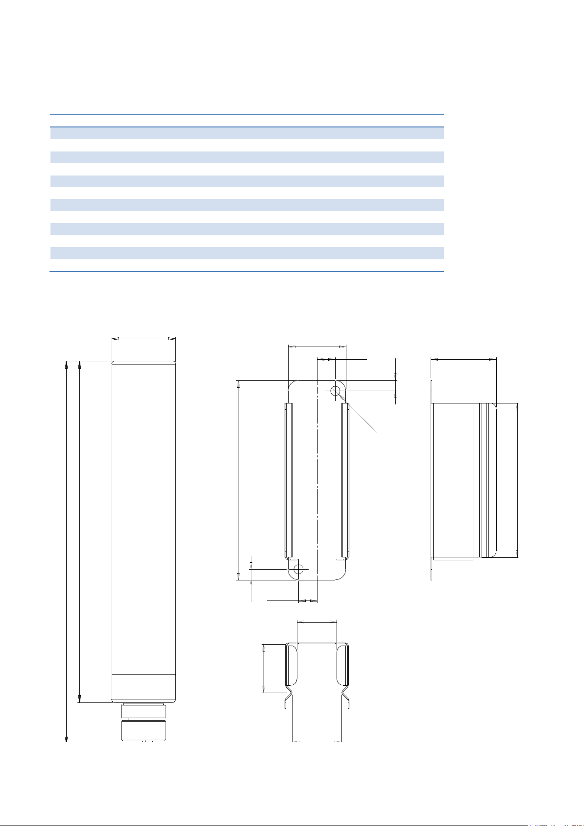
The total height of MTR265B is 227 mm including removable connector.
There are two mounting holes on the corners of MTR265B-SP wall mounting bracket which have a diameter
of 4,5 mm. Choose correct type of screws depending on the wall material and with maximum of 4mm
diameter.
Mounting location
Radio technical perspective
MTR265B transmitter has a typical indoor maximum range of 50...100 m depending on the number and
quality of obstacles between the transmitter and the receiver. The best range is achieved when there is a
line-of-sight between the transmitter and receiver. In unrestricted open space (outdoors) the maximum
range can be over 500 meters. Walls and obstacles attenuate the signal and therefore reduce the range.
Especially closed steel structures attenuate radio signals very effectively, and installation in or behind them
should be avoided if possible. In the worst possible conditions, e.g. very thick reinforced concrete walls,
bomb shelters, deep underground spaces, the range can be even less than 10 meters.
However, most spaces with metal walls have doors or openings of some sort, and these openings and the
seals between them and the door, leak radio signals if the seals are made of non-conductive material. As a
rule of thumb the device should be mounted with antenna positioned vertically just like the antenna of the
radio receiver. The doors that leak the radio signals usually have larger vertical dimensions than horizontal
and thus leak the vertically polarized signal from the vertically mounted antenna more effectively.
One more factor that affects the final transmission range and performance is the local radio interference
and noise condition. This should be seriously considered in heavy industrial installation sites or any sites
with lots of power electronics around, for example power inverters and large electric motors. At least the
radio receiver should be located as far as possible from this type of radio interference sources.
In any case, it is worth considering the installation location from the radio technical perspective too.
MTR265B with external sensor gives more flexibility in choosing the installation location of the transmitter
itself. But even for this, the guidelines given in the next chapter should be followed when choosing the
installation location for the external sensor.
Measurement perspective
MTR265B transmitter can be installed in the limits of the length of the sensor form the place where
temperature is to be measured. When choosing the installation location one must consider multiple effects
affecting the temperature distribution in the space.
Considerations for cold storage applications
Air tends to layer such that cooler air is lower and warmer air is higher. Evaporators and fans blow cold air
into their vicinity. Doors, vents, lamps and other heat sources warm up their surroundings. The device or
external sensor should be installed into a spot whose temperature follows as closely as possible to the
temperature of the target products in the same space.
Therefore the device or the sensor should not be installed:
• close to the floor or ceiling,
• onto the floor or ceiling,
• near the evaporator of a refrigeration unit,
• near the place where the cold/hot air flows from the evaporator/radiator,
• near a door or other opening and definitely not above one,
• close to a lamp or other heat source nor
• in a location where it is likely that the device will be covered up or get mechanically damaged.