Kurz 504FTB User manual

Kurz Instruments Inc. December 13, 2007
360210-AH Rev.A 504/534FTB Installation AH - 1
Installation
Figure AH-1 504FTB and 534FTB with venturi flow conditioner.
WARNING: Your warranty will be voided if your unit is not installed in accordance
with this user’s guide. Make sure you read and thoroughly understand the
installation portion of this guide before you attempt to install your unit. If you
have any questions, contact your Kurz customer service representative before
attempting installation.
Mounting
The 504 and 534FTB In-line flow transmitters are generally mounted with a flange pipe
fitting but thread is sometimes used on smaller line sizes. See the product brochures
(DCN 367524 for the 504FTB and DCN 360723 for the 534FTB) for Kurz mounting
accessories. It is important for the mounting design to consider the force that will be
exerted on the flow body from the piping. It is best (often required by the plumbing
code) to support the process piping on both sides of the flow meter so it may be
removed without the piping bending or moving much making it hard to re-install.
Flow Body Location and Orientation:
The In-Line flow meters are available for ½” to 6” piping. The principle difference
between the 504FTB and 534FTB is the type and efficiency of flow conditioner which

Kurz Instruments Inc. December 13, 2007
360210-AH Rev.A 504/534FTB Installation AH - 2
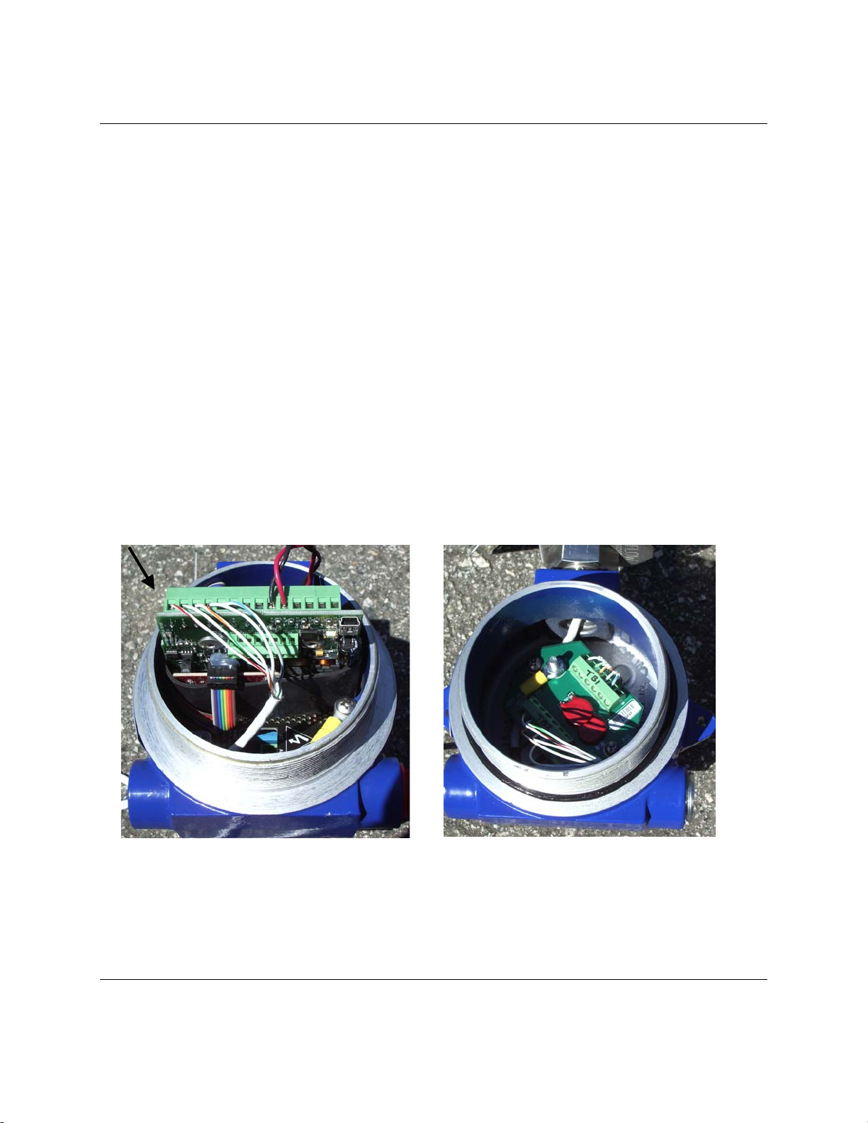
can be seen in the two photographs shown above.
•504FTB has only a small perforated plate flow conditioner. Requires straight
runs in the 15 to 40 D range to obtain field data with-in 2% of the laboratory
calibration. So field calibration may be needed depending on the accuracy
needed.
•534FTB has a venturi flow conditioner. This has no straight run requirements to
be within 2% of the laboratory calibration. Field calibration is generally not
needed.
The quick start guide shows this very clearly in the second figure for in-line meters. In
addition to what is shown here, the double elbow case not shown, will introduce swirl
that can further aggravate the data and straight run length requirements.
Horizontal Mounted Meters
Any orientation works fine.
If there is condensate running along the bottom of the pipe, the sensor will last
longer if its electronics head is vertical up tilting down to no more than to 8 AM or
4 PM positions.
Vertical Mounted Meters
Flow going up works well under all conditions
Flow going down works well except near the zero flow region, below 50 SFPM or
0.25 SMPS.
High Dew Point applications
If the application is near the dew point, it will condense inside the pipe walls when
the gas is cooling as it flows along. Insulating the piping will reduce the condensate on
the inside walls. In these cases, it is best to mount the sensor from the bottom at about
7:30 or 4:30. Vertical from the top can cause water to flow on to the stings, or if
mounted from the bottom the condensate will aggravate sting corrosion. Condensate
(water or other liquids) on the sensor will cause false high flow readings while the
sensor evaporates the liquid.
Hot or cold process fluid
Insulation on the piping will reduce any temperature gradients that will introduce
a false high or low reading. Hot fluid in a pipe with cold walls will tend to read low for
sensors which are center line mounted and read high for Cold fluids in a warmer
ambient.

Kurz Instruments Inc. December 13, 2007
360210-AH Rev.A 504/534FTB Installation AH - 3
Pump or Fan inlets
Vacuum or pump inlets from ambient air can result in extra sensor cleaning
schedules to remove dirt build up. The fan inlet is often below atmospheric pressure
and when the humidity is near 100% there will be condensation formed at these
locations. The condensate will allow dirt to stick to the sensor more than in the absence
of condensate. A better solution is to place the flow meter after the fan or pump where
the pressure is higher, thus the relative humidity will be lower and avoid condensation
and dirt sticking to the sensor.

Kurz Instruments Inc. December 13, 2007
360210-AH Rev.A 504/534FTB Installation AH - 4
1. ¾” FNPT Sensor support port
(TA or Transmitter Attached
version)
Conduit or cable port (TS or
transmitter separate version)
2. Backlit 2x16 LCD and 20 key
button interface
3. ¾” FNPT signal and power
conduit ports.
4. Safety Label and Product ID
tag.
5. Main I/O wiring terminal block
for sensor, power, RS-485 and
4-20 mA outputs, TB1
6. AC power input. 85 to 265
VAC 50/60 Hz. 1 phase.
7. Power indicator: Green LED,
right side of TB1
8. USB mini-B connector
9. Optional hardware, AI, DO, DI,
Purge valve, I/O connector
TB6
10. External and internal ground
lug locations. Shielded wire
pig-tail termination location.
7
Figure AH-2. Location of major components

Kurz Instruments Inc. December 13, 2007
360210-AH Rev.A 504/534FTB Installation AH - 5
Electronics Head Orientation
The electronics head is provided in two standard orientations compared to the sensor
flow arrow or flow direction. When looking at the display and the flow is to the right, this
is the normal configuration (see figure AH-1) and flowing to the left is reverse. This
option is selected in the model part number when the unit is ordered.
Rotating the head in the field can damage the sensor wires and result in a loose
connection which results in water leakage or other warrantee and hazardous area
safety violations.
TS Version
For transmitter separate versions (TS) there are two enclosure groups. The sensor
enclosure mounts as described above and contains just a sensor wire terminal board.
Sensor Wires
Figure AH-3. Sensor electronics enclosure and sensor J-box with covers removed
The electronics enclosure contains the sensor control board, optional AC power supply
and LCD/keypad and is mounted via the pipe nipple as shown in Figure AH-4. Two U
clamps around the pipe nipple to a metal mounting adaptor (Optional Kurz part #

Kurz Instruments Inc. December 13, 2007
360210-AH Rev.A 504/534FTB Installation AH - 6
700494-) frame or pipe stand are sufficient. It is important to know that the sensor serial
number must be matched with the same serial number electronics unit. These two
parts are not interchangeable unless the electronics configuration file is matched with
the sensor serial number.
Power and Signal wires. 2x
¾” conduit ports
Conduit seal for
Ex applications
Sensor Wire
Port: ¾” NPT
Figure AH-4. Examples of Unistrut and Pipe mounting of the TS configured electronics
using the optional mounting kit, 700494-.
Field Wiring
Proper wiring installation of the MFT B-Series flow transmitters may include some or all
the flowing issues:
•Safety Grounding and Explosion-Proof enclosure connections.
•Water ingress protection

Kurz Instruments Inc. December 13, 2007
360210-AH Rev.A 504/534FTB Installation AH - 7
•DC or AC power requirements and connection.
•Analog Output configuration and wiring of the 4-20 mA signals.
•Discrete Alarms
•Purge sensor air solenoid
•Zero/Mid/Span daily drift test (EPA 40 CFR part 60 or 75 support)
•Serial Digital Interface
•5-wire sensor connection for the TS configuration
•Clip-on Ferrite for all signal wires if not in shielded conduit
•Flex service connection to sensor probe support.
Please read the complete text of the sections and study the wiring diagram examples
which are relevant to your model before performing the installation.
Safety
To ensure compliance with General Safety requirements the metal enclosures must be
grounded to minimize the chance of electrical shock. For Explosive Atmospheres,
proper grounding minimizes the chance of sparks occurring, potential ignition sources,
outside an enclosure at its mechanical interfaces if a fault current was to flow. Both
internal and external grounds are available; see the wiring diagrams DCN 342038 and
342039.
For hazardous gas areas, wiring going into and out of the explosion-proof enclosures
must be done through a conduit seal or cable gland rated for explosion-proof
applications (Class 1 Div. 1 or Zone 1) attached directly to the enclosure. See Figure
AH-4. These seals are not needed for non-incendiary designs (Class 1 Div. 2 or Zone
2).
For hazardous areas it is important to not connect or disconnect any
wiring when the circuits are energized, the resulting spark could
cause ignition.
Three 3/4" FNPT fittings are provided on the electronics enclosure. The one pointing out
radially is used for the sensor probe support or its wiring in a TS configuration. The other
two ports exiting opposite the sensor port are for power and signal wiring. One port is
typically used for AC power and the other for the signal wires. DC powered models can
use both ports for signal/power wiring. Consult your local electrical code for installation
requirements.

Kurz Instruments Inc. December 13, 2007
360210-AH Rev.A 504/534FTB Installation AH - 8
Water Ingress Protection
The leading cause of a malfunctioning flow transmitter is water penetration in to the
sensor electronics or wiring terminals. The electronics enclosures have a NEMA 4X or
IP66 rating but the transmitters are still subject to water damage if not properly installed
and maintained.
Protective measures for keeping water out of the flow transmitter components.
•Installation of conduit seals (Ex type potting Y work well) near the enclosures on
all ports.
•Most cable gland designs not only provide for shielded cable termination but an
environmental seal against dirt and water.
•Routing of conduit or cable using a water loop and drain near the enclosure ports
•Keep the enclosure lids on tight using the supplied o-rings.
•Positive pressure dry purge air to the enclosure will keep condensation out (few
PSI from a regulator).
Conformal coating of the circuit boards is standard but this only protects against
condensation of trapped water vapor which forms from cooling inside the
enclosures/conduit. Every 10 minutes a sensor and wiring leakage test is performed.
This will set an alarm (Modbus, LCD and NE-43) when excessive leakage is observed.
Flex Wiring Connection for Sensor Inspections
To support periodic and preventative maintenance, the sensor electrical connections
should be done with extra cable or flex conduit length. This allows the sensor to be
removed from the process for inspection and or cleaning without disconnecting the
wiring. The transmitter attached (TA) versions have only power and 4-20 mA wires are
being routed out and use standard electrical wring practice as shown in Figure AH-5.
However, the trouble is maintaining the EMC requirements on the wiring at the same
time. If we are using a transmitter separate (TS) version, the sensor is remote from its
electronics, we must use an approved shielding method. The 5-wire sensor connections
are described in a later section.

Kurz Instruments Inc. December 13, 2007
360210-AH Rev.A 504/534FTB Installation AH - 9
Figure AH-5. Flex sensor connection for
service loop, TA version using Liquid Tight
Conduit.
Approved EMC tight flexible, shielded electrical connections for the TS 5-wire sensor
wiring
•Braid reinforced pneumatic hose; Hydraulic line hose
•Corrugated Stainless Steel tubing, with compression fitting at each end. Gas
appliance flex fittings may be long enough and are available at local home
improvement outlets.
•Braded Shielded cable with peripheral bonded shield cable glands
Figure AH-6. Metal Braid Hydraulic Lines, corrugated gas appliance line and braided
shielded cable all work well for EMC shielding of 5-wire sensor connections.

Kurz Instruments Inc. December 13, 2007
360210-AH Rev.A 504/534FTB Installation AH - 10
Do not use Liquid tight Flex conduit for 5-wire sensor connections, shielding is not
effective.
Typical Hook-Up Wiring Diagrams
For both the AC & DC powered versions of the MFT B-Series, typical summarized wiring
diagrams for most applications are available as defined in DCN 342038. This covers the
TS and transmitter attached (TA) configurations. Examples for 4-20 mA connections and
Modbus are shown along with the terminal definitions and cable wiring notes.
For the transmitter separated (TS) enclosure configuration, the 5-wire sensor
connections must be made as shown in DCN 342039. The connection between the
enclosure groups must be shielded to maintain the CE rating.
24 VDC Powered Flow Transmitters
The 24 VDC power is a nominal voltage since all circuits have a regulated supply and will
work between 18 and 30 VDC. You may also use an unregulated power supply with 50
to 60 Hz ripple as long as the instantaneous voltage is between 18 and 30 VDC.
Surge currents during sensor warm up could require up to 1 A and will fall off after it
warms up in about 20 seconds. At no flow the current will be about 0.1 A and about 0.3
A for high flow rates (12,000 SFPM). The power is protected against reverse polarity so
if no current flows or there is no output signal you may want to check the polarity against
the wiring diagram, DCN 342038.
The flow transmitter is grounded. The 24 VDC power and 4-20 mA signal have MOVs
(metal oxide varistors) to clamp voltage spikes going into the unit. These are 56 V
nominal (voltage level at 1 mA) and do not conduct significant current below about +/- 36
VDC relative to ground. Consequently, the isolated 4-20 mA signals, alarms etc., can
not have a significant common mode or bias voltage to prevent leakage currents on the
MOVs, which can cause an error in the flow measurement if occurring on the 4-20 mA
output.

Kurz Instruments Inc. December 13, 2007
360210-AH Rev.A 504/534FTB Installation AH - 11
Figure AH-7. DC and AC power connection.
AC Powered Units
A universal input 85-265 VAC and 50-60 Hz supply generates a nominal 24 VDC to
power the unit. The AC wiring uses one of the two ¾” conduit ports for the signal wiring.
The AC powered units have a long pull tab attached to the plug so it is easy to remove
the plug and connect the AC wiring with a 1/8” screw driver.
Figure AH-8 AC power pull tab to be removed.
Discard the pull tab as the power wiring can be used to guide the plug
in/out of the power supply.
These wires must be inside the plastic insulator sleeve to prevent the
wires from catching in the threads of the explosion proof lid. The
internal ground can be made via the AC power plug or a 10-32 stud on
the PCB.
24 VDC
AC Power
Connector
Green Power
LED

Kurz Instruments Inc. December 13, 2007
360210-AH Rev.A 504/534FTB Installation AH - 12
There is no means of disconnecting power for this unit. You will need a disconnect per
your local electrical code.
Analog Output
Loop powered wiring: The 4-20 mA linear output is a loop powered isolated signal.
The positive output terminal is diode protected against reverse voltage. The principle
wiring diagrams for these are 342038 and 342039.
Self powered wiring: The output may be self-powered in the non-isolated mode by
jumpering +24 VDC to one of the two + 4-20 mA terminals. Then the 4-20 mA output
would be taken from the 4-20 mA negative terminal to ground. A simplified AO wiring
drawing or this mode of operation is shown in diagram 342045. To use it in the non-
isolated mode, the receiving current should be sensed with an isolated input to avoid
ground loop currents.
AO capabilities: The 4-20 mA circuit has an 11 VDC compliance at the full 20 mA
current. So, on a 24 VDC 4-20 mA circuit, at least 11 VDC will be dropped across the 4-
20 mA output, the balance on the load resistor and wiring. For example, with a 250 ohm
load, at 20 mA the voltage drop will be 5 V on the load resistor, 19 V across the 4-20 mA
output or AO terminals. With higher voltage supplies, you have correspondingly higher
load resistance available. As a loop-powered 4-20 mA output and a 24 VDC power
supply, you can drive 600 Ω and still support the 21 mA NE-43 alarm. Do not exceed 36
VDC on the loop-powered interface or you may have leakage current from the protective
MOVs causing an error in the measurement. In summary, a loop-powered configuration
places a customer provided DC power source, the MFT B-Series output and load
resistance(s) all in series.
NE-43 alarm support on the 4-20 mA signal is also provided. This means normal
operation is clipped between 3.8 and 20.5 mA. Meter faults or sensor kickout are
indicated with either a low or high alarm on the 4-20 mA output. See the diagnostic
section for more information.
Alarms
The two optically coupled solid state relays (SSR), may be used for just about any flow
logic you can think of, sensor error output, or totalizer mode pulses. Each SSR is rated
for 0.5 A, 24 V AC/DC. As with the other I/O terminals, there are 48 V MOVs for surge
protection on this device. You must not exceed 36 V to ground or you will cause leakage

Kurz Instruments Inc. December 13, 2007
360210-AH Rev.A 504/534FTB Installation AH - 13
and may overheat and damage the MOV which can fail in a short. Again, see the wiring
diagram 342038 for the specific alarm terminals.
Serial Communications
There are two independent serial ports on the MFT B-Series. A mini-type B USB
connector with Kurz driver can act as a COM port so “remote” terminal operation is
possible or the RS-485 port can be used for the Modbus protocol and multipoint
communications. The USB port can be used in instead of the small LCD/keypad option
to view data, configure the meter or extract diagnostic data. The upload or download of
the meter configuration can be done on either the USB or Modbus port using the Kurz
provided program KzComm. The advantage of the Modbus port is greatest when you
have multiple meters on the bus allowing access to all of them from one location, your
heated or cooled office or control room.
USB
Any terminal emulator program may be used to act as a remote terminal to the MFT B-
Series. HyperTerminal, which comes with all Windows versions except for Vista, is
sufficient and supports Xmodem for transferring and storing the MFT B-Series
configuration files. See below for Windows Vista. This takes about five seconds at 9600
baud, the only supported USB driver baud rate. The character format is 1 start bit, 1
stop, 8 data, and no parity. The program KzComm may also be used if you only need to
save/print the configuration files, but it is not a terminal emulator.
If HyperTerminal is not installed on your computer you may add it by going to the
Add/Remove Programs within the Control Panel and clicking the Windows Setup tab.
Then choose the Communication group and within it you will find the button to select
HyperTerminal. After this you may be asked for your Windows disk so this may be
installed. Refer to your Windows documentation if you need more information on
HyperTerminal. Once the program is installed, you start HyperTerminal which will
prompt you for a name of the connection, ie Kurz MFT B-Series, then an icon. Next you
select the communications port, ie COM 4 and finally you press Configure and set the
baud rate to 9600, data bits to 8, parity to none, stop bits to 1 and flow control to none.
Once you have verified this works, save the configuration under File, Save.
Windows Vista machines do not include HyperTerminal so you will need to download
and install it. This program is available for download from its designer at the following
web site: http://www.hilgraeve.com/htpe. After installing the program configure it as

Kurz Instruments Inc. December 13, 2007
360210-AH Rev.A 504/534FTB Installation AH - 14
described in the previous paragraph. You may want to put a short cut to this program in
your Start menu.
RS-485/Modbus
The RS-485 interface is half duplex and supports baud rates of 9600, 14400, 19200,
38400 and 57600. Wiring is a shielded twisted pair, two signal lines and one shield
connection. The signal lines can be connected in any order provided the 485 bus is
biased so the flow meter knows which signal is positive. See 342038 for a wiring
example of this. A junction tee (see www.turck.com ) between the network bus and
instrument drop is recommended so instruments may be removed for service without
interruption to the network bus.
Desk computers and laptops can interface to the
RS-485 devices using a USB dongle converter.
We recommend the industrial version from
EasySync, available from Kurz (PN 700491) or
the manufacture. This device is optically
isolated, screw terminal interface with metal
enclosure and status LEDs, with a biased bus
allowing the auto-polarity detection to work. .
EasySync’s devices have a known issue with the Microsoft Windows Vista operating
device.
The Modbus interface must be set for device address, protocol, baud rate, and byte
order. See 342042 for more information on how to configure or verify Modbus
communications settings. Once properly connected and configured, you will not only see
the yellow LED flash for RS-485 receive activity, you will see the green LED flash for
transmit or response of the flow transmitter. The MFT B-Series unit has two red LEDs
used for receive and transmit, respectively. The full protocol specification and register
variable map is found in the serial communications section of the manual.
5-Wire Sensor Connections
For the TS version you must field install the wiring between the sensor and its electronics
enclosures. In addition to the field wiring diagram 342038 you need to refer to 342039 for
the TS part. This is a 5-wire connection which must use quality wire whose wire
resistance is less than 1 Ωper wire. Each wire must be matched within 0.01 Ωor 10 mΩ

Kurz Instruments Inc. December 13, 2007
360210-AH Rev.A 504/534FTB Installation AH - 15
so the lead length compensation can work properly. Without this, the Factory calibration
and temperature compensation will not hold in the field. If the individual wires do not
meet the matching specification, their length must be trimmed or extended until they
match. The terminal strip for the sensor wire will accept up to 12 AWG wire (2.05 mm)
which is good for 630 feet (192 m) between the sensor and electronics. However, the
electronics terminal block TB1 is rated for 14 AWG (1.63 mm) max wire size.
To maintain the CE compliance of the product in the TS configuration, one must maintain
a good shield around the 5 wires. This can be done with rigid conduit, EMT or a braided
shielded multi-conductor cable between the sensor junction box and the sensor
electronics enclosures. Conduit seals directly to the enclosures are still needed to meet
the explosion-proof ratings. Peripherally bonded shielded cable glands work well but a
simple cable gland and shield pigtail ground connection is sufficient. Hawke America
(281 445 7400, www.ehawke.com ), makes a whole line of cable glands for shielded
cable. Their Model 501 universal is one of many and has Exd safety ratings too, see
installation info also. Some of these sizes and cable are also available as accessories
from Kurz. See section above with more recommend wiring methods for the 5-wire
sensor connections.
Not recommend for CE compliance on the 5-wire sensor connections of the TS
configuration:
Type
Reason not to use it.
Unshielded
twisted Pair, UTP
No shielding.
Armor Cable
Spiral wrap armor wires are not an EMI
shield. Looks like an inductor at RF
frequencies.
Flex Conduit
Spiral wrap shell is not an EMI shield.
Liquid Tight
Conduit
Better shield than flex conduit but will not
hold up well over time due to oxidation of
the metal wrap joints that degrade the EMI
shield.

Kurz Instruments Inc. December 13, 2007
360210-AH Rev.A 504/534FTB Installation AH - 16
Optional Clip-on Ferrite for Signal Wires
If the I/O connections, 24 VDC, Modbus, analog outputs, or analog inputs (4-20 mA) are
not connected by a shielded connection, conduit or multi-conductor braded shield cable,
then these wires must be clipped in a ferrite to meet the EMC specifications. Figure AH-
9 shows and example of this type of wiring.
Figure AH-9 Clip-on Ferrite for I/O wires to be CE compliant without proper cable or
conduit shielding.
The Ferrite can be purchased from Kurz as part number 600029- or from the following
manufactures:
Steward 28A2024.0A2
Fair-rite: 0443164151:
Stock available from Kurz or Digi-Key Corporation (www.digikey.com )
Clip-on
Ferrite

Kurz Instruments Inc. December 13, 2007
360210-AH Rev.A 504/534FTB Installation AH - 17
Orientation of the LCD Keypad
Turn the power off to the unit before performing this procedure to prevent damage and
protect you from explosions ignited from electrical sparks.
Within the electronics head, the LCD keypad can be mounted in any one of four 90 °
rotated positions for best viewing and hand access. It mounts to four standoffs using the
screws seen on the keypad. When performing the display rotation, standard electronics
handling procedures to prevent ESD must be used. Use a wrist strap between yourself
and the enclosure body before taking the display board out to rotate it.
The short ribbon cable between the sensor electronics and display board must have its
connectors fully seated in the PCBs before you carefully screw down the board using the
provided screws. RTV works as an adhesive to keep the connector attached to the
display board. It is applied between the outside of the connector and PCB, not the inside
on the electrical pins .The ribbon cable connectors have a pin 1 mark which must match
that of the PCB connector at each end. The ribbon cable will route towards the center of
each PCB when properly mounted.
There is an LCD contrast adjustment on the back of the LCD/keypad board which can be
adjusted with a small flathead screwdriver as needed for best viewing of the screen.
However, it is Factory set for equal viewing at 0 and 60 degrees C so it is not optimized
at room temperature. When too cold the display is white and when too hot, the display
will be dark.
Figure AH-10. 90° display rotation options.
This manual suits for next models
1
Table of contents
Other Kurz Transmitter manuals