Kusam-meco KM 1812EL User manual

G 17, Bharat Industrial Estate, T. J. Road,
Sewree (W), Mumbai - 400 015. INDIA.
Sales Direct : (022) 24156638
Tel. : (022) 24124540, 24181649. Fax : (022) 24149659
Website : www.kusamelectrical.com
www.kusam-meco.co.in
®MODEL - KM 1812EL
OPERATION MANUAL
®®
AN ISO 9001:2008 COMPANY
DIGITAL
ELCB TESTER

MODEL - KM 1812EL
DIGITAL
ELCB TESTER
Caution! R
Warning! R
efer to this manual before using the meter.
isk of electric shock.
Meter is protected throughout by double
insulation or reinforced insulation.
Observe the International Electric symbols listed below.
TABLE OF CONTENTS
PAGE
01
02
03
03
04
05
06
07
07
07
08
08
09
10
Safety Precautions........................................................
Features........................................................................
Connections..................................................................
Instrument Layout.........................................................
Lid Instruments.............................................................
RCD Test - Time Delay.................................................
Preparation For Measurement......................................
Battery Replacement.....................................................
Servicing And Calibration..............................................
Test Certificate..............................................................
Warranty........................................................................
Specifications................................................................
Fuse Replacement........................................................
Cleaning And Storage...................................................
TITLE
EARTH NEUTRAL LINE
MULTIFREQUENCY (50Hz-60Hz)
C
Battery
OK
LIT
DO NOT PROCEED LIT
WIRING CORRECT
N-E P-N P-E
AUTO POWER OFF
0º
180º OFF
10 15 20
30
35
50
100
125
150
175
250
275
300
375
500
3
5
7
PRESS TO Switch Instrument ON
and TO AUTO-TEST DEVICE
RCD Rated Trip (mA)
DIGITAL
RCD / GFCI / ELCB TESTER
Version A = 240Vac
Version C = 220Vac
Version B = 230Vac
Version D = 110Vac

01 02
1. SAFETY PRECAUTIONS :
Electricity can cause severe injuries even with low voltage or
currents. Therefore it is extremely important that you read the
following information before using your digital RCCB / ELCB tester.
1.1 This instrument must only be used and operated by a
competent trained person and in strict accordance with the
instructions. We will not accept liability for any damage or
injury caused by misuse or non compliance with instructions
and safety procedures.
1.2 Never open your digital RCCB / ELCB tester except for battery
replacement. (See Battery Replacement section).
1.3 Always inspect you digital RCCB / ELCB tester and test leads
before use for any sign of abnormality or damage. If any
abnormal conditions exist (broken test leads, cracked case,
display faulty etc.) do not attempt to take any measurement or
use the tester. Return your digital RCCB / ELCB tester to your
nearest Distributor for service.
1.4 Never replace the protective fuse with any other than the
specified or approved equivalent.
1.5 Your digital RCCB / ELCB tester has been designed with your
safety in mind. However, no design can completely protect
against incorrect use. Electrical circuits can be dangerous and/
or lethal when a lack of caution or poor safety practice is used.
Be careful of the voltage presented above 24V as these pose
a shock Hazard.
1.6 Pay attention to cautions and warnings which will inform you of
potentially dangerous procedures.
1.7 Rated environmental conditions :
(1) Indoor use.
(2) Installation Category III.
(3) Pollution Degree 2.
(4) Altitude up to 2000 Meters.
(5) Relative Humidity 80% Maximum.
(6) Ambient Temperature 0-40ºC.
2. SPECIFICATIONS :
Current Settings
Current Selection
Phase Start Selection
0º and 180º
Over-Temperature Protection
Wiring Correctness indication
Trip Indicator
Phase Polarity Trip Indicator
Operating Voltage (L-E) 50Hz or 60Hz
1812EL-A
1812EL-B
1812EL-C
1812EL-D
Voltmeter (L-E)
Timer Resolution
Timer Accuracy
Current Accuracy
Voltmeter Resolution
Voltmeter Accuracy
Operating Temperature
Storage Temperature
Battery
Current Specified at
3ma, 5mA, 7mA, 10mA,
15mA, 20mA, 30mA,35mA,
50mA, 100mA, 125mA,
150mA, 175mA,
250mA, 300mA, 375mA,
500mA.
Rotary Switch
Referenced to Earth
Yes
Yes (3 sensors)
Yes (LEDs)
Yes (LCD)
Yes (LCD)
Referenced to Earth
240Vac
230Vac
220Vac
110Vac
20Vac-280Vac
1mS (max time= 2.999S)
±2% rdg ±2mS
±5% ±1mA
1Vac
±2% ±1Vac
-5ºC to 45ºC
-10ºC to 85ºC
8 ´AA batteries
Bat OK Led = Vbat >7.5v
Measure battery voltage at
start up
Operating voltage

03 04
3. FEATURES :
v2 Lines ´
vVery low consumption.
vMicroprocessor controlled.
vTwo years factory warranty.
vMenu driven.
vAccurate digital readout of disconnection time.
vAutomatic data hold function.
vZero crossing circuitry permit testing at 0º or 180º.
vDisconnection phase polarity shown on L.C.D. display.
vAuto-off and off override.
vPolarity trip indicator (Positive or Negative phase)
vWiring polarity indicator.
vMeasure voltage between Line and Earth before testing.
16 Characters Liquid Crystal Display.
4. CONNECTIONS :
Line (Hot) Probe
Connection Neutral Probe
Connection
Earth (Ground) Probe
Connection
LINE NEUTRAL EARTH
apply only
Operating Voltage ±10% / 50Hz or 60 Hz.
5. INSTRUMENT LAYOUT :
EARTH NEUTRAL LINE
MULTIFREQUENCY (50Hz-60Hz)
C
Battery
OK
LIT
DO NOT PROCEED LIT
WIRING CORRECT
N-E P-N P-E
AUTO POWER OFF
0º
180º OFF
10 15 20
30
35
50
100
125
150
175
250
275
300
375
500
3
5
7
PRESS TO Switch Instrument ON
and TO AUTO-TEST DEVICE
RCD Rated Trip (mA)
DIGITAL
RCD / GFCI / ELCB TESTER
5
4
3
1
2
1. On Switch.
Test Button Switch.
2. Selection Switch.
0º -160º
3. Current Selection Rotary Switch.
4. Intelligent L.C.D.
5. Wiring Check / Indicator.

05 06
LID INSTRUCTIONS :
INSTRUCTIONS DIGITAL RCD / GFCI / ELCB TESTER
IMPORTANT
1. The tester check the time taken for a given selected current to trip the breaker under test.
The test show the phase at tripping (related to the earth terminal).
2. The ELCB Test operates between Line & Earth. Ensure that you operate on operating Voltage (Version A, B, C or D).
3. The tester is protected against over-temperature. If over-temperature message appears, allow time for instrument to
cool down. During the cool down period, the instrument switch off automatically to save battery life.
TRIPPING TIME TEST
A preselected current is injected L-E. The value of the current may be selected with the rotary switch.
wOnce the Instrument is switched “ON”, the display show the battery voltage for about two seconds.
wThereafter, the display is ready to wait for phase selection and to measure the voltage L-E..
wTHE “TEST” BUTTON CAN BE DEPRESSED. Once the phase selection has been done and the voltage has been
detected L-E. .
wOnce Test is depressed, the tester will automatically start the test.
The Instrument displays :
1. The Tripping time (mS) of the RCD (time to break under fault level)
2. The Phase when tripping occurred.
3. The Voltage (Vac) L-E at the start of the test.
4. The approximative percentage error of the current injected.
Version A = 240Vac
Version B = 230Vac
Version C = 220Vac
Version D = 110Vac
Should the RCD not trip within the testing time capability of the instrument, the display will show T=2.999S
and “Hold >OVER”, meaning the RCD did not trip below 19.999S. The tripping point is out of the Range of
the instrument (or RCD faulty).
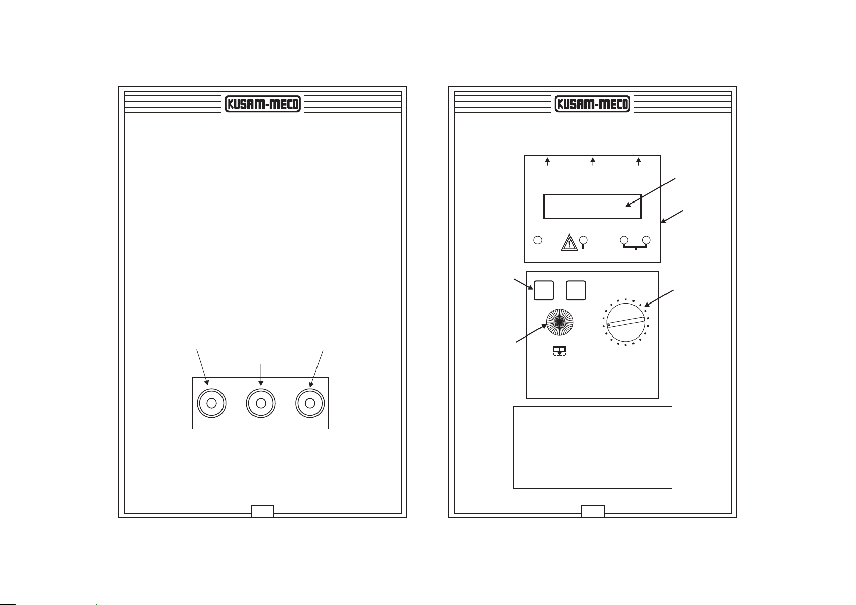
TEST PROCEDURE
1. Insert the leads into Instrument.
2. Switch Instrument “ON”.
3. Select the current using the rotary switch.
4. Select positive (0º) or negative (180º) edge to start.
5. Connect the tester to the circuit under test.
6. The tester measures and display the voltage L-E.
7. Check wiring. Proceed only if wiring is correct.
8. Depress “Test” button to automatically test.
wTest start immediately if voltage is present.
wThe Test stops automatically when Breaker trips.
wTest results are shown on the display.
wWhen Instrument is utilized on two wires (L-E), wiring check
must be disregarded.
wThis instrument is “Domestic rated”.
Once “Test” button is depressed :
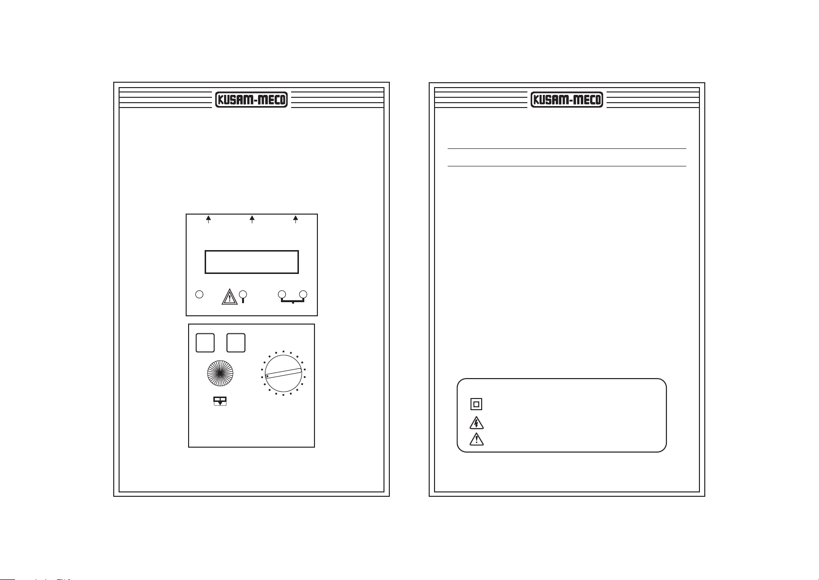
6. RCD TEST - TIME DELAY :
Turn instrument “ON” by pressing the “TEST-ON” button.
The L.C.D. display will come to the following Screen :
The instrument will detect and show the battery voltage
when power ON.
The tester wait for voltage to be measured
and phase selection can be changed.
Phase selection has been changed so
that testing will start on a negative going edge.
The leads have been connected and the voltage
between L-E is 234Vac (version B shown in this example).
“Test” button has been depressed. Test in progress since 2.999s.
The voltage between L-E was 234V before testing started.
“TRP < 2%” It means the voltmeter.
Accuracy : ± 2% ±1V AC
TRP = Tripped, Display on Hold
at 2.999s Tripped on + edge of signal (180º).
Battery Voltage
12Vdc
Vac L-E=000V
0º
Vac L-E=000V
180º
Vac L-E=234V
180º
234V T=2.999s
Test in Progress
234V T=2.999s
180º Hold ®TRP < 2%

07 08
7. PREPARATION FOR MEASUREMENT :
Before testing always check the following :
vThe BAT OK led lights at power ON. If the BAT OK led does
not light, replace batteries with the same Specification.
vCheck the battery voltage on the LCD display.
vThere is no visual damage to the Instrument or test leads.
vTest lead continuity with a continuity meter.
8. BATTERY REPLACEMENT :
1. The BAT OK led lights constantly while instrument power is on.
If not, please replace batteries with the same specification.
2. Your digital RCCB / ELCB tester’s batteries are situated under
the tester. Disconnect the test leads from the Instrument,
remove the battery cover and the batteries.
3. Replace with eight 1.5V R6 or L6 batteries, taking care to
observe correct polarity.
4. Replace the battery cover.
9. FUSE REPLACEMENT :
1. The fuse is located in the battery compartment. To replace the
fuse, proceed as per Battery Replacement Section to open the
battery cover, then remove and replace the fuse located on the
side of the batteries.
2. Make sure to place the fuse protection cover (small rubberized
fuse cover).
3. Only replace with the same specification fuse (1A fast blow).
10. SERVICING AND CALIBRATION :
Your Digital RCCB.ELCB tester has been factory calibrated.
However, it is of good practice to have your instrument CERTIFIED
by a National Calibration Facility and CHECKED every year by a
professional workshop
11. CLEANING AND STORAGE :
Periodically wipe the case with a damp cloth and detergent; do not
use abrasives or solvents.
If the instrument is not to be used for periods longer than 60 days,
remove the batteries and store them separately.
WARNING
TO AVOID ELECTRONIC SHOCK OR DAMAGE TO THE
METER, DO NOT GET WATER INSIDE THE CASE.

09 10
MUMBAI
TEST CERTIFICATE
DIGITAL ELCB TESTER
This Test Certificate warrantees that the product has been
inspected and tested in accordance with the published
specifications.
The instrument has been calibrated by using equipment
which has already been calibrated to standards traceable
to national standards.
MODEL NO. ________________
SERIAL NO. ___________
DATE: ___________
ISO 9001
REGISTERED
QC
PASS
KUSAM-MECO
WARRANTY
Each “KUSAM-MECO” product is warranted to be free from defects in
material and workmanship under normal use & service. The warranty
period is one year (12 months) and begins from the date of despatch of
goods. In case any defect occurs in functioning of the instrument, under
proper use, within the warranty period, the same will be rectified by us
free of charges, provided the to and fro freight charges are borne by you.
This warranty extends only to the original buyer or end-user customer of a
“KUSAM-MECO” authorized dealer.
This warranty does not apply for damaged Ic’s, fuses, burnt PCB's,
disposable batteries, carrying case, test leads, or to any product which in
“KUSAM-MECO’s” opinion, has been misused, altered, neglected,
contaminated or damaged by accident or abnormal conditions of
operation or handling.
“KUSAM-MECO” authorized dealer shall extend this warranty on new
and unused products to end-user customers only but have no authority to
extend a greater or different warranty on behalf of “KUSAM-MECO”.
“KUSAM-MECO’s” warranty obligation is limited, at option, free of charge
repair, or replacement of a defective product which is returned to a
“KUSAM-MECO” authorized service center within the warranty period.
THIS WARRANTY IS BUYER’S SOLE AND EXCLUSIVE REMEDY AND
IS IN LIEU OF ALL OTHER WARRANTIES, EXPRESS OR IMPLIED,
INCLUDING BUT NOT LIMITED TO ANY IMPLIED WARRANTY OF
MERCHANTABILITY OR FITNESS FOR A PARTICULAR PURPOSE.
“KUSAM-MECO” SHALL NOT BE LIABLE FOR ANY SPECIAL,
INDIRECT, INCIDENTAL OR CONSEQUENTIAL DAMAGES OR
LOSSES, INCLUDING LOSS OF DATA, ARISING FROM ANY CAUSE
WHATSOEVER.
All transaction are subject to Mumbai Jurisdiction.
This manual suits for next models
4
Table of contents