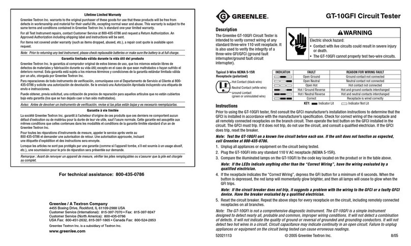
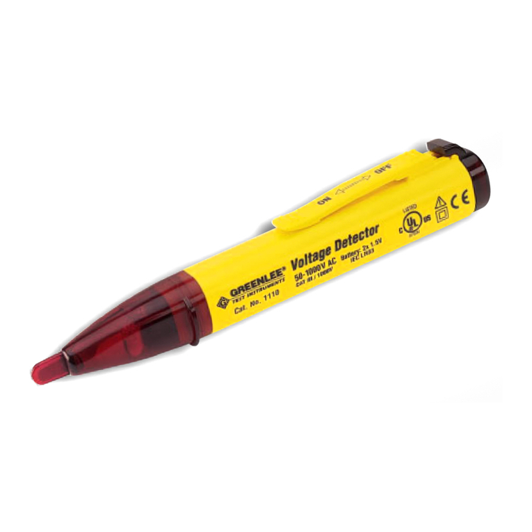
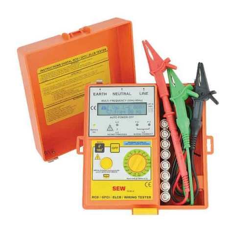
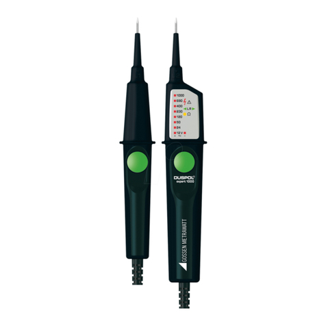
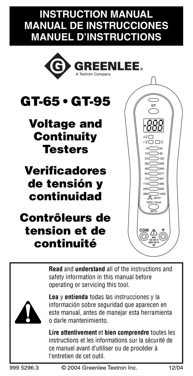
Greenlee GT-55e User manual

52021951 © 2005 Greenlee Textron Inc. 8/05
GT-55e •GT-85e
Voltage, Continuity, and
Phase Rotation Testers
INSTRUCTION MANUAL
Read and understand all of the
instructions and safety information
in this manual before operating or
servicing this tool.
English ............. 1–16
Français ......... 17–32
Italiano........... 33–48
Deutsch .......... 49–64
Español .......... 65–80
Português........ 81–96
Nederlands ..... 97–112

2
Description
The Greenlee GT-55e and GT-85e are fully automatic
voltage detectors capable of reading voltages up to 690 V
AC or DC. Both models also check continuity, indicate
phase rotation, have Residual Current Detector (RCD) trip
test capability, and an integrated light for testing under low
lighting conditions.
The GT-55e display utilizes LED indicators. The GT-85e has
an LCD display with backlight and can measure resistance.
Safety
Safety is essential in the use and maintenance of Greenlee
tools and equipment. This instruction manual and any
markings on the tool provide information for avoiding
hazards and unsafe practices related to the use of this tool.
Observe all of the safety information provided.
Purpose of This Manual
This instruction manual is intended to familiarize all
personnel with the safe operation and maintenance
procedures for the Greenlee GT-55e and GT-85e Voltage,
Continuity, and Phase Rotation Testers.
Keep this manual available to all personnel. Replacement
manuals are available upon request at no charge.
Do not discard this product or throw away!
For recycling information, go to
www.greenlee.com.
KEEP THIS MANUAL
All specifications are nominal and may change as design
improvements occur. Greenlee Textron Inc. shall not be liable for
damages resulting from misapplication or misuse of its products.
® Registered: The color green for electrical test instruments is a
registered trademark of Greenlee Textron Inc.
Lifetime Limited Warranty
Greenlee Textron Inc. warrants to the original
purchaser of these goods for use that these products
will be free from defects in workmanship and material
for their useful life, excepting normal wear and abuse.
This warranty is subject to the same terms and
conditions contained in Greenlee Textron Inc.’s
standard one-year limited warranty.
3
GT-55e • GT-85e
Important Safety Information
This symbol is used to call your attention to hazards or
unsafe practices which could result in an injury or
property damage. The signal word, defined below,
indicates the severity of the hazard. The message after
the signal word provides information for preventing or
avoiding the hazard.
SAFETY ALERT SYMBOL
Immediate hazards which, if not avoided, WILL result
in severe injury or death.
Hazards which, if not avoided, COULD result in severe
injury or death.
Hazards or unsafe practices which, if not avoided, MAY
result in injury or property damage.
Read and understand this material
before operating or servicing this
equipment. Failure to understand
how to safely operate this tool
could result in an accident causing
serious injury or death.

4
Important Safety Information
Electric shock hazard:
• Do not operate with the case or battery cover open.
• Before opening the case or battery cover, remove
the test leads from the circuit and shut off the unit.
Failure to observe these warnings could result in
severe injury or death.
Electric shock hazard:
• Do not apply more than the rated voltage between
any two input terminals, or between any input
terminal and earth ground.
• Do not contact the test lead tips or any uninsulated
portion of the accessory.
Failure to observe these warnings could result in
severe injury or death.
Electric shock hazard:
• Do not expose this unit to rain or moisture.
• Do not use the unit if it is wet or damaged.
• Use test leads that are appropriate for the
application. Refer to the category and voltage rating
of the test lead.
• Inspect the test leads or accessory before use. They
must be clean and dry, and the insulation must be in
good condition.
• Use this unit for the manufacturer’s intended
purpose only, as described in this manual. Any
other use can impair the protection provided by the
unit.
Failure to observe these warnings could result in
severe injury or death.
Electric shock hazard:
Contact with live circuits could result
in severe injury or death.

5
GT-55e • GT-85e
Important Safety Information
Electric shock hazard:
• Do not attempt to repair this unit. It contains no
user-serviceable parts.
• Do not expose the unit to extremes in temperature
or high humidity. Refer to “Specifications.”
Failure to observe these precautions may result in
injury and can damage the unit.
Electric shock hazard:
Do not change the measurement function while the
test leads are connected to a component or circuit.
Failure to observe this precaution may result in injury
and can damage the unit.
Electric shock hazard:
• Unless measuring voltage, shut off and lock out
power. Make sure that all capacitors are discharged.
Voltage must not be present.
• Using this unit near equipment that generates
electromagnetic interference can result in unstable
or inaccurate readings.
Failure to observe these warnings could result in
severe injury or death.

6
Identification
GT-55e
1. – probe
2. + probe
3. Light
4. Risk of electric shock
5. Continuity indication with
tone
6. Phase rotation indication
7. – V DC reverse polarity
indication with tone
8. Light switch
9. Insulated hand grip
10. ~ VAC (both LEDs lit)
11. Voltage level indication
Symbols on the Unit
Warning—Read the instruction manual
Double insulation
Recycle product in accordance with manufacturer’s
directions
GT-55e
3
9
8
4
5
6
7
11
10
21
GT-85e
3
7, 10
14
6
4
9
8
13
11
12
5
1 2
GT-85e
1. –probe
2. + probe
3. Light
4. Risk of electric shock
5. Continuity indication
with tone
6. Phase rotation
indication
7. –V DC reverse polarity
indication with tone
8. Light switch
9. Insulated hand grip
10. + V DC and ~ VAC
11. Voltage level indication
and reading
12. Ohm switch
13. Ohm symbol and
reading
14. Low battery indication

7
GT-55e • GT-85e
Operation
1. Refer to “Typical Measurements”for specific
measurement instructions.
2. Test the unit on a known functioning circuit or
component.
•If the unit does not function as expected on a
known functioning circuit, replace the battery.
•If the unit still does not function as expected, send
the unit to Greenlee for repair.
3. Take the reading from the circuit or component to be
tested.
4. If the tester is used in a noisy environment, ensure
that the sound level of the tester is perceptible.
Illumination
Probe Light
GT-55e
GT-85e
Electric shock hazard:
Contact with live circuits could result
in severe injury or death.
Electric shock hazard:
Do not change the measurement function while the
test leads are connected to a component or circuit.
Failure to observe this precaution may result in injury
and can damage the unit.

8
Typical Measurements
Double-pole AC Voltage Measurement
GT-55e
GT-85e
Note: If the tester is
used in a noisy
environment, ensure
that the sound level of
the tester is perceptible.
The tester will sound
with reverse polarity of
DC voltage.
GT-55e
GT-85e
Continuity /
Diode Test
GT-55e
GT-85e
DC Voltage
Note: The continuity/diode test is only
possible when batteries are installed
and in good condition.

9
GT-55e • GT-85e
Typical Measurements
Ohm Measurements
(GT-85e only)
GT-85e
•This test is not always appropriate for testing whether a
circuit is not live (off). To determine whether the circuit
is not live, use both probes L1 and L2.
•Firmly grasp the insulated grips of the tester to increase
the sensitivity of this test.
Note: Standing on wooden steps, ladders, or insulated
floor coverings can impair single-pole voltage detection.
Unfavorable lighting conditions, such as direct sunlight,
or a non-operational, grounded AC system can also
impair detection.
GT-55e
GT-85e
>100 V
Grasp
firmly
Note: The resistance test is only possible when batteries
are installed and in good condition.
Single-pole Voltage Detection Test

10
Phase Rotation Test
Rotary Phase of a Three-Phase Mains
Right Rotary Field
GT-55e
GT-85e
Grasp
firmly
Typical Measurements
GT-55e
GT-85e
Grasp
firmly
Left Rotary Field
In three-phase electrical systems, the phases are
separated by 120 degrees of phase shift. The first phase is
the reference phase; the second phase lags the first by 120
degrees; the third lags the second by 120 degrees.
Three-Phase Voltage Waves
ABCABC
BCABCA
120°
240°
360°

11
GT-55e • GT-85e
Typical Measurements
Phase Rotation Test (cont’d)
The phases are identified with at least three different
conventions:
•L1, L2 and L3
•A, B and C
•R, S and T
The phase sequence function of the GT-55e and GT-85e
can determine the phase relationship between two AC
voltages.
1. Connect L1 and L2 to two of the phases. Firmly grasp
the insulation grips of the tester to increase the
sensitivity of this test. Compare the result on the
display with the “Phase Sequence Table.”
Phase Sequence Table
2. If the phase rotation is counterclockwise , switch
the wires to produce a clockwise rotation.
Note: Ensure that the test electrodes (probe tips) make
good contact with two phases of a three-phase mains
while testing the phase rotation. For absolute determina-
tion of a clockwise rotation, it is necessary to reverse the
position of the two probes and verify that the phase
indication changes. The indication or can be affected
by unfavorable light conditions, by protective clothing, or
in insulated locations.
Probe L1 Probe L2
Connection Connection Display
L1 / A / R L2 / B / S
L3 / C / T
L2 / B / S L3 / C / T
L1 / A / R
L3 / C / T L1 / A / R
L2 / B / S

12
RCD Trip Test
During voltage tests in systems equipped with RCD circuit
breakers, a RCD switch can be tripped at a nominal
residual current of 10 mA or 30 mA by measuring the
voltage between L and PE.
The GT-55e and GT-85e are equipped with an internal load
enabling the tripping of an RCD protection device of 10 mA
or 30 mA.
Note: To prevent tripping an RCD, charge the unit first by
connecting the probes between L and N for approximately
5 seconds. Immediately afterwards, connect the probes
between L and PE.
Typical Measurements

13
GT-55e • GT-85e
Specifications and Accuracy
GT-55e and GT-85e
Operating and Storage Conditions:
Temperature: –10 °C to 55 °C
Humidity: 0% to 85% relative humidity
Altitude: 2000 m maximum
Pollution Degree: 2
Indoor use only.
Remove batteries before storing. Store in dry and
closed area. If tool is transported in extreme
temperatures, a recovery time of at least 2 hours is
required before operation.
Measurement Categories: CAT III 1000 V; CAT IV 600 V
Type of Protection: IP64
CE: EN61326 :
EN55011 :
Safety:
EN61010-1 : 2001
EN61010-031 : 2002
EN61243-3 : 1998
EN61243-3/CI : 2000
EN60529 : 1992/AI2000
GS38
Functionality:
EN61243-3 : 1998
EN61557-7 : 1997
EN61557-10 : 2001
EN61557-1 : 1997
GT-55e
Voltage Range: 6 V to 690 V AC/DC
Bargraph Resolution: ±6, 12, 24, 36, 50, 120, 240, 400,
690 V
Voltage Detection: Automatic
Acoustic Signal Sound:
AC Voltage: Yes
–DC Voltage: Yes
Polarity Detection: Full range
Range Detection: Automatic
Response Time: < 0.1 s
Frequency Range, DC: 45 Hz to 65 Hz
Automatic Load (RCD): Yes
Peak Current: Is < 0.2 A / Is (5 s) < 3.5 mA
Operation Time: ED (DT) = 30 s
Recovery Time: 10 min
Auto Power On: < 12 VAC/DC
Power Supply: 2 x 1.5 V Micro IEC LR03
Power Consumption: Max. 30 mA / approx. 250 MΩ
Single-pole Voltage Detection Test
Voltage Range: 100 V to 690 V AC
Frequency Range: 45 Hz to 65 Hz
Continuity Test
Threshold: < 200 kΩ
Test Current: < 20 µA
Overvoltage Protection: 690 V AC/DC

14
Specifications and Accuracy (cont’d)
Rotary Field Indication
Voltage Range (LEDs): 100 V to 690 V
Frequency Range: 50 Hz to 60 Hz
Measurement Principle: Double-pole and firmly hold the
grip (L2)
GT-85e
Voltage Range: 6 V to 690 V AC/DC
Bargraph Resolution: ±6, 12, 24, 36, 50, 120, 240, 400,
690 V
LCD Voltage Range: 10 V to 690 V AC/DC
LCD Resolution: 1 V
Accuracy: ±(3% reading + 2 V)
Voltage Detection: Automatic
Acoustic Signal Sound:
AC Voltage: Yes
–DC Voltage: Yes
Polarity Detection: Full range
Range Detection: Automatic
Response Time: < 0.1 s/BAR; < 2 s/reading
Frequency Range, DC: 45 Hz to 65 Hz
Automatic Load (RCD): Yes
Peak Current: Is < 0.2 A / Is (5 s) < 3.5 mA
Operation Time: ED (DT) = 30 s
Recovery Time: 10 min
Auto Power On: < 12 VAC/DC
Power Supply: 2 x 1.5 V Micro IEC LR03
Power Consumption: Max. 30 mA / approx. 250 MΩ
Single-pole Voltage Detection Test
Voltage Range: 100 V to 690 V AC
Frequency Range: 45 Hz to 65 Hz
Continuity Test
Threshold: < 200 kΩ
Test Current: < 20 µA
Overvoltage Protection: 690 V AC/DC
Rotary Field Indication
Voltage Range (LEDs): 100 V to 690 V
Frequency Range: 50 Hz to 60 Hz
Measurement Principle: Double-pole and firmly hold the
grip (L2)
Resistance Test
Resistance Range: 0 kΩto 2 kΩ
Accuracy: ±(3% reading + 10 Ω)
Test Current: < 0.5 mA
GT-55e (cont’d)

15
GT-55e • GT-85e
Measurement Categories
These definitions were derived from the international
safety standard for insulation coordination as it applies to
measurement, control, and laboratory equipment. These
measurement categories are explained in more detail by
the International Electrotechnical Commission; refer to
either of their publications: IEC 61010-1 or IEC 60664.
Measurement Category I
Signal level. Electronic and telecommunication equipment,
or parts thereof. Some examples include transient-
protected electronic circuits inside photocopiers and
modems.
Measurement Category II
Local level. Appliances, portable equipment, and the
circuits they are plugged into. Some examples include light
fixtures, televisions, and long branch circuits.
Measurement Category III
Distribution level. Permanently installed machines and the
circuits they are hard-wired to. Some examples include
conveyor systems and the main circuit breaker panels of a
building’s electrical system.
Measurement Category IV
Primary supply level. Overhead lines and other cable
systems. Some examples include cables, meters,
transformers, and other exterior equipment owned by the
power utility.
Statement of Conformity
Greenlee Textron Inc. is certified in accordance with ISO
9000 (2000) for our Quality Management Systems.
The instrument enclosed has been checked and/or
calibrated using equipment that is traceable to the National
Institute for Standards and Technology (NIST).

16
Maintenance
Battery Replacement
1. Disconnect the unit from the circuit.
2. Remove the screw from the battery cover.
3. Remove the battery cover.
4. Replace the batteries (observe polarity).
5. Replace the cover and the screw.
4 mm Tip
Replacement
Replacement tips, part
number 52022444,
can be ordered from
Greenlee.
Cleaning
Periodically wipe the case with a damp cloth and mild
detergent; do not use abrasives or solvents.
Electric shock hazard:
•Do not attempt to repair this unit. It contains no
user-serviceable parts.
•Do not expose the unit to extremes in temperature
or high humidity. Refer to “Specifications.”
Failure to observe these precautions may result in
injury and can damage the unit.
Electric shock hazard:
•Do not operate with the case or battery cover open.
•Before opening the case or battery cover, remove
the test leads from the circuit and shut off the unit.
Failure to observe these warnings could result in
severe injury or death.

52021951 © 2005 Greenlee Textron Inc. 8/05
GT-55e •GT-85e
Contrôleurs de tension,
continuité et rotation
de phase
MANUEL D’INSTRUCTIONS
Lire attentivement et bien
comprendre toutes les instructions
et les informations sur la sécurité
de ce manuel avant d‘utiliser ou de
procéder à l‘entretien de cet outil.

18
Description
Les détecteurs de tension Greenlee GT-55e et GT-85e
peuvent lire les tensions allant jusqu’à 690 V c.a. ou c.c.
Les deux modèles vérifient également la continuité, la
rotation de phase, peuvent vérifier le déclenchement d’un
détecteur de courant résiduel et comportent un éclairage
intégré pour la vérification dans des zones sombres.
L’afficheur du GT55e utilise des indicateurs à DEL. Le
GT-85e a deux ACL rétroéclairés et peut mesurer la
résistance.
Sécurité
Lors de l’utilisation et de l’entretien des outils et des
équipements de Greenlee, votre sécurité est une priorité.
Ce manuel d’instructions et toute étiquette sur l’outil
fournit des informations permettant d’éviter des dangers
ou des manipulations dangereuses liées à l’utilisation de
cet outil. Suivre toutes les consignes de sécurité
indiquées.
Dessein de ce manuel
Ce manuel d’instructions est conçu pour que le personnel
puisse se familiariser avec les méthodes d’utilisation et
d’entretien sûres des contrôleurs de tension, de continuité
et de rotation de phase GT-55e et GT-85e de Greenlee.
Mettre ce manuel à la disposition de tous les employés. On
peut obtenir des exemplaires gratuits sur simple demande.
Ne pas se débarrasser de ce produit ou le jeter !
Pour des informations sur le recyclage, visiter
www.greenlee.com.
CONSERVER CE MANUEL
Toutes les spécifications sont nominales et peuvent changer avec
l’amélioration de la conception. Greenlee Textron Inc. ne peut être
tenue responsable des dommages résultant d’une application
inappropriée ou d’un mauvais usage de ses produits.
® Enregistré : La couleur verte des instruments de vérification
électrique est une marque de commerce déposée de Greenlee
Textron Inc.
Garantie à vie limitée
La société Greenlee Textron Inc. garantit à l’acheteur
d’origine de ces produits que ces derniers ne
comportent aucun défaut d’exécution ou de matériau
pour la durée de leur vie utile, sauf l’usure normale.
Cette garantie est assujettie aux mêmes conditions que
celles contenues dans les modalités et conditions
de la garantie limitée standard d’un an de
Greenlee Textron Inc.

19
GT-55e • GT-85e
Consignes de sécurité importantes
Ce symbole met en garde contre les risques et les
manipulations dangereuses pouvant entraîner des
blessures ou l’endommagement du matériel. Le mot
indicateur, défini ci-dessous, indique la gravité du
danger. Le message qui suit le mot indicateur indique
comment empêcher le danger.
SYMBOLE
D’AVERTISSEMENT
Danger immédiat qui, s’il n’est pas pris en
considération ENTRAINERA des blessures graves,
voire mortelles.
Danger qui, s’il n’est pas pris en considération,
POURRAIT entraîner des blessures graves, voire
mortelles.
Dangers ou manipulations dangereuses qui, s’ils ne
sont pas pris en considération, POURRAIENT
EVENTUELLEMENT entraîner des dommages à la
propriété ou causer des blessures.
Lire attentivement et bien
comprendre cette documentation
avant d’utiliser ou de procéder à
l’entretien de cet équipement.
Négliger de comprendre comment
utiliser cet outil en toute sécurité
pourrait provoquer un accident et
entraîner des blessures graves, voire
mortelles.

20
Consignes de sécurité importantes
Risques de décharge électrique :
• Ne pas utiliser lorsque le boîtier ou le couvercle du
compartiment à pile est ouvert.
• Avant d’ouvrir le boîtier ou le couvercle du
compartiment à piles, retirer les fils d’essai du
circuit et mettre l’appareil hors tension.
L’inobservation de ces consignes pourrait entraîner des
blessures graves, voire mortelles.
Risques de décharge électrique :
• Ne pas appliquer plus que la tension nominale entre
deux bornes d’entrée, ou entre une borne d’entrée et
une prise de terre.
• Ne pas entrer en contact avec les extrémités des fils
d’essai ou avec toute autre partie non isolée de
l’accessoire.
L’inobservation de ces consignes pourrait entraîner des
blessures graves, voire mortelles.
Risques de décharge électrique :
• Ne pas exposer cet appareil à la pluie ou à
l’humidité.
• Ne pas utiliser cet appareil s’il est mouillé ou
endommagé.
• Utiliser les fils d’essai conformes à l’application. Se
reporter à la catégorie et la tension nominale du fil
d’essai.
• Vérifier les fils d’essai ou l’accessoire avant de les
utiliser. La pièce ou les pièces doivent être propres
et sèches et l’isolation en bon état.
• Utiliser cet appareil uniquement dans le but pour
lequel il a été conçu, comme il est décrit dans ce
manuel. Toute autre utilisation peut altérer le
système de protection de cet appareil.
L’inobservation de ces consignes pourrait entraîner des
blessures graves, voire mortelles.
Risques de décharge électrique :
Un contact avec des circuits sous
tension pourrait entraîner des
blessures graves, voire mortelles.
This manual suits for next models
1
Table of contents
Languages:
Other Greenlee Circuit Tester manuals

Greenlee
Greenlee LT-100 User manual

Greenlee
Greenlee GT-65e User manual

Greenlee
Greenlee PairMapper User manual

Greenlee
Greenlee PG1 User manual

Greenlee
Greenlee 1110 User manual

Greenlee
Greenlee GT-65 User manual

Greenlee
Greenlee GT-10 Manual

Greenlee
Greenlee 5708 User manual

Greenlee
Greenlee 5715 User manual

Greenlee
Greenlee AFI-100 User manual