Kvaser Air Bridge M12 User’s Guide 9 (26)
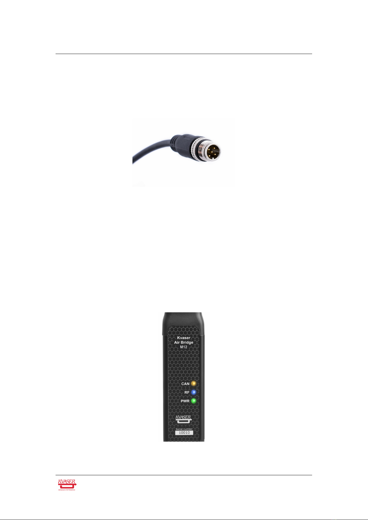
3 Kvaser Air Bridge M12 hardware
In this section you can read more about the CAN channel, power supply and LED
indicators.
3.1 Hardware installation
The Kvaser Air Bridge M12 is a wireless CAN device that can be used together
with another Kvaser Air Bridge M12 to form a CAN bridge. A Kvaser Air Bridge
M12 device can thereby be paired with any other Kvaser Air Bridge M12, i.e.
’one-to-any’, thereby forming a pair of Kvaser Air Bridge M12 units. Although not a
Kvaser Air Bridge Light HS, which is sold as one of a pair of preconfigured CAN
bridge units, the Kvaser Air Bridge M12 can also be preconfigured as a pair of
units and as such it will only need to be configured once.
The advantage of using a Kvaser Air Bridge M12, as opposed to a preconfigured
Kvaser Air Bridge Light HS, is that it provides options to freely pair and unpair
Kvaser Air Bridge M12 units and to alter the operational settings to better suit the
specific system characteristics and user application. All Kvaser Air Bridge devices
are designed to coexist with each other.
The Kvaser Air Bridge M12 is driver free, with only limited configuration needed,
which is simple using the Kvaser Air Bridge Utility CLI. Pairing can be performed
during commissioning, although it is primarily intended to be controlled from a host
application by means of special messages on the CAN bus defined in the
Management Interface. Once paired, the two Kvaser Air Bridge M12 devices need
just be connected to their CAN segments, nothing else is required!
When connected to a CAN bus system, the Kvaser Air Bridge M12 device will by
default determine the bit rate used by the attached CAN system using Automatic
Baud Rate Detection (autobaud), see Section 3.5, Autobaud Detection, on
Page 11. Once the autobaud detection has completed successfully, the devices
will transmit CAN messages back and forth until they are powered down. Note:
The autobaud feature can be overridden to speed up connection time, by selecting
one of four supported bit rates. As the Kvaser Air Bridge protocol provides an
internal bit rate conversion scheme, the bit rates may be chosen independently for
every Kvaser Air Bridge M12 device. Bit rate selection is done within the Kvaser Air
Bridge Utility CLI or via the Management Interface.
A Kvaser Air Bridge device will only forward CAN messages between the two
attached CAN networks. Error frames and arbitration information will not be
forwarded since this information is only applicable for the local physical network.
The recommended minimum distance between two Kvaser Air Bridge devices is
0.5 m.
Kvaser AB, Mölndal, Sweden — www.kvaser.com